EP1004258B1 - Half hollow extrusion with an attachment element slidable along the extrusion - Google Patents
Half hollow extrusion with an attachment element slidable along the extrusion Download PDFInfo
- Publication number
- EP1004258B1 EP1004258B1 EP99121829A EP99121829A EP1004258B1 EP 1004258 B1 EP1004258 B1 EP 1004258B1 EP 99121829 A EP99121829 A EP 99121829A EP 99121829 A EP99121829 A EP 99121829A EP 1004258 B1 EP1004258 B1 EP 1004258B1
- Authority
- EP
- European Patent Office
- Prior art keywords
- semi
- connecting element
- hollow section
- head
- hollow profile
- Prior art date
- Legal status (The legal status is an assumption and is not a legal conclusion. Google has not performed a legal analysis and makes no representation as to the accuracy of the status listed.)
- Expired - Lifetime
Links
- 238000001125 extrusion Methods 0.000 title description 4
- 239000000463 material Substances 0.000 claims abstract description 3
- 239000002184 metal Substances 0.000 claims description 2
- 230000013011 mating Effects 0.000 claims 1
- 238000007373 indentation Methods 0.000 abstract 1
- 230000006835 compression Effects 0.000 description 5
- 238000007906 compression Methods 0.000 description 5
- 238000006073 displacement reaction Methods 0.000 description 4
- 238000004873 anchoring Methods 0.000 description 1
- 238000005516 engineering process Methods 0.000 description 1
- 238000003780 insertion Methods 0.000 description 1
- 230000037431 insertion Effects 0.000 description 1
- 238000004519 manufacturing process Methods 0.000 description 1
- 239000002984 plastic foam Substances 0.000 description 1
Images

Classifications
-
- F—MECHANICAL ENGINEERING; LIGHTING; HEATING; WEAPONS; BLASTING
- F16—ENGINEERING ELEMENTS AND UNITS; GENERAL MEASURES FOR PRODUCING AND MAINTAINING EFFECTIVE FUNCTIONING OF MACHINES OR INSTALLATIONS; THERMAL INSULATION IN GENERAL
- F16B—DEVICES FOR FASTENING OR SECURING CONSTRUCTIONAL ELEMENTS OR MACHINE PARTS TOGETHER, e.g. NAILS, BOLTS, CIRCLIPS, CLAMPS, CLIPS OR WEDGES; JOINTS OR JOINTING
- F16B19/00—Bolts without screw-thread; Pins, including deformable elements; Rivets
- F16B19/02—Bolts or sleeves for positioning of machine parts, e.g. notched taper pins, fitting pins, sleeves, eccentric positioning rings
-
- F—MECHANICAL ENGINEERING; LIGHTING; HEATING; WEAPONS; BLASTING
- F16—ENGINEERING ELEMENTS AND UNITS; GENERAL MEASURES FOR PRODUCING AND MAINTAINING EFFECTIVE FUNCTIONING OF MACHINES OR INSTALLATIONS; THERMAL INSULATION IN GENERAL
- F16B—DEVICES FOR FASTENING OR SECURING CONSTRUCTIONAL ELEMENTS OR MACHINE PARTS TOGETHER, e.g. NAILS, BOLTS, CIRCLIPS, CLAMPS, CLIPS OR WEDGES; JOINTS OR JOINTING
- F16B37/00—Nuts or like thread-engaging members
- F16B37/04—Devices for fastening nuts to surfaces, e.g. sheets, plates
- F16B37/045—Devices for fastening nuts to surfaces, e.g. sheets, plates specially adapted for fastening in channels, e.g. sliding bolts, channel nuts
- F16B37/046—Devices for fastening nuts to surfaces, e.g. sheets, plates specially adapted for fastening in channels, e.g. sliding bolts, channel nuts with resilient means for urging the nut inside the channel
Definitions
- the invention relates to a semi-hollow profile, especially made of extruded or rolled Light metal, with at least one along the Half-hollow sliding element, wherein the semi-hollow profile on at least one side has continuous wall recess whose Boundary edges as inward legs trained and front with one to the profile interior directional profiling are provided.
- Such a hollow profile is known from EP-A-0 040 180 become known, the one trained as a hanging stick Stand shows on which a horizontal beam is arranged adjustable in height.
- the inside directed legs have a position tooth profile, in whose tooth gaps two at the head of the connecting element engage fastened bolts. Via a screw connection the head braced against the tooth profile.
- the invention is based on the object Fasteners at selectable points on the Semi-hollow profile can be anchored continuously without Screw connections are used.
- the solution to this problem according to the invention consists in that the profiling takes the form of a Knurling against which the in Interior of the semi-hollow profile slidably guided head of the connecting element under high tensile load specific surface pressure can be positively pressed, the Connecting element on the protruding from the semi-hollow profile Part of an eyelet to hold one Tension member, in particular a tension belt.
- the invention is based on the idea that Fixing the connecting element on the semi-hollow profile desired position by pressing the head of the Connection element against the knurling bring about. This requires a force that Head of the connecting element against the knurling presses.
- the connecting element on the outside an eyelet to the Tensile stress e.g. through a loop through the eye To produce tension belt.
- At least one the head of the Connection element pressing against the profiling Spring provided, for example as a by the Cavity guided, convex in cross section Leaf spring can be formed.
- the spring in One or more on the head, for example on the Profiling facing away from the head of the Arrange connecting element.
- Another variant is that the material of the Connecting element softer than that of the semi-hollow profile is. In this way, the edges or tips dig up the profiling in the assigned surface of the Connection element and lead to one Constraint as long as there is a force acting on it Press the connection element against the profiling.
- the spring force mentioned at the outset needs in the context of a another example of the invention only as large to be dimensioned so that when you move the Connecting element along the semi-hollow profile only a fixation in the sense of a frictional connection to the desired position generated.
- the effective positive Connection between the head of the connecting element and the profiling is done by another force, For example, a pulling force on the from the Half-hollow protruding part of the connecting element attacks.
- FIG. 1 In the embodiment of Figure 1 is a Half-hollow profile (1) shown in cross section, in which a Connecting element (2) along the interior of the Semi-hollow profile (1) is displaceable.
- the semi-hollow profile (1) has a continuous one on at least one wall Wall recess (3) through which the shaft of the Connecting element (2) is guided to the outside.
- the cross section of the semi-hollow profile (1) shown is just as an example instead of many other possible ones Understand cross-sectional shapes.
- the continuous Wall recess (3) from two inwardly projecting legs (4) bounded longitudinally at their free ends have continuous profiles (5).
- the profile (5) is in shape a knurling educated. It is essential that this Profiling (5) during the extrusion of the Semi-hollow profile (1) by a following Extrusion tool arranged unit are formed.
- the sheet to be rolled is knurled first in the roller table and then rolled to the profile.
- Example of Figure 1 uses a leaf spring (7) which in Interior of the semi-hollow profile (1) is arranged and the Head (6) of the connecting element (2) against the Profileing (5) presses. This spring force should are sufficient to prevent the Connecting element (2) along the semi-hollow profile (1) prevent.
- a positive anchoring of the connecting element (2) results in the embodiment by Traction symbolically dotted by the dash shown traction element (15) is initiated.
- This Traction can, for example, by a tension belt or another traction element can be generated.
- this traction (15) is the head (6) of the Connection element (2) firmly against the profiling (5) excited, the high specific surface pressure of the protruding edges, corners or tips of the profiling (5) provide for a frictional engagement that prevents the Connection element (2) prevented.
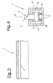
- FIG. 2 is an alternative to Leaf spring (7) shown in Figure 1.
- it points individual connecting element (2) at least one compression spring (9), one in the connecting element (2) along it Axle-guided spring bolts (8) against the bottom of the Half-hollow profile (1) presses.
- This can be the training the spring bolt (8) also a profiling exhibit.
- the power of Compression spring (9) is sufficient to the head (6) of the Connection element (2) against the profiling (5) to press.
- connection element (2) move along the semi-hollow profile (1) by hand the connection element (2) is pushed slightly against the spring (7) or (9) presses and thus the head (6) of the Connecting element (2) from the profiling (5) distant.
- FIG. 4 It is also shown in Figure 4 that instead of the in Figure 1 illustrated leaf spring (7) also a Pressure rail (14) can be used facing the floor of the semi-hollow profile (1) is supported by compression springs (13) and against the head (6) of the connecting element (2) the profiling (5) or (12) presses.
- the representation of the Figure 5 shows the insertion and displacement of the Connecting element by looking in the direction of the arrow a manual force of the connecting element (2) against the Pressure rail (14) can act, causing the teeth (11,12) disengage and the connecting element (2) is displaceable along the semi-hollow profile (1).
- cross-sectional shape of the Semi-hollow profile (1) can be designed in any way can.
- the cross-sectional shape shown in the drawing is only intended to convey the functional principle without the invention is limited to this form.
- the invention can be used wherever it matters is going to hold objects on a base, for example, boxes, boxes, stacks or the like to clamp on a pallet or the like.
- the Base area then only needs the Semi-hollow profiles (1) to be equipped to connect any fastener at any point. from that there is also the possibility of more than one Attach the connecting element (2) to the semi-hollow profile (1) and thus the bracing with several To be able to perform connecting elements.
- the invention can also be connected vertically Use semi-hollow profiles (1), for example around Hold objects on an upright wall surface.
Landscapes
- Engineering & Computer Science (AREA)
- General Engineering & Computer Science (AREA)
- Mechanical Engineering (AREA)
- Mutual Connection Of Rods And Tubes (AREA)
- Springs (AREA)
- Holo Graphy (AREA)
- Prostheses (AREA)
- Separation Using Semi-Permeable Membranes (AREA)
- Joints Allowing Movement (AREA)
- Absorbent Articles And Supports Therefor (AREA)
- Pharmaceuticals Containing Other Organic And Inorganic Compounds (AREA)
- Orthopedics, Nursing, And Contraception (AREA)
Abstract
Description
Die Erfindung bezieht sich auf ein Halbhohlprofil, insbesondere aus stranggepresstem oder gerolltem Leichtmetall, mit mindestens einem längs des Halbhohlprofils verschiebbaren Verbindungselement, wobei das Halbhohlprofil an mindestens einer Seite eine durchlaufende Wandaussparung besitzt, deren Begrenzungsränder als nach innen gerichtete Schenkel ausgebildet und stirnseitig mit einer zum Profil-Innenraum gerichteten Profilierung versehen sind.The invention relates to a semi-hollow profile, especially made of extruded or rolled Light metal, with at least one along the Half-hollow sliding element, wherein the semi-hollow profile on at least one side has continuous wall recess whose Boundary edges as inward legs trained and front with one to the profile interior directional profiling are provided.
Halbhohlprofile dieser Art sind in vielfältigen Ausführungsformen bekannt. Am häufigsten werden solche Profile mit mindestens einer, im Querschnitt hammerkopfartigen, durchlaufenden Nut versehen, um darin Verbindungselemente in Form von Hammerkopf-Schrauben oder dergleichen zu verschieben. Auf diese Weise werden an der gewünschten Stelle andere Profile klemmtechnisch befestigt.Semi-hollow profiles of this type are available in many different ways Embodiments known. The most common are Profiles with at least one, in cross section Hammer head-like, continuous groove provided in it Fasteners in the form of hammer head screws or to postpone the like. This way, at the desired position other profiles in terms of clamping technology attached.
Ein solches Hohlprofil ist durch die EP-A-0 040 180 bekannt geworden, die einen als Hängestiel ausgebildeten Ständer zeigt, an dem ein horizontaler Träger höhenverstellbar angeordnet ist. Die nach innen gerichteten Schenkel weisen ein Lagezahnprofil auf, in dessen Zahnlücken zwei am Kopf des Verbindungselementes befestigte Bolzen eingreifen. Über eine Verschraubung wird der Kopf gegen das Lagezahnprofil verspannt. Such a hollow profile is known from EP-A-0 040 180 become known, the one trained as a hanging stick Stand shows on which a horizontal beam is arranged adjustable in height. The inside directed legs have a position tooth profile, in whose tooth gaps two at the head of the connecting element engage fastened bolts. Via a screw connection the head braced against the tooth profile.
Damit ist aber nur eine stufenweise Verstellung des Verbindungselementes möglich.But this is only a gradual adjustment of the Connection element possible.
Der Erfindung liegt die Aufgabe zugrunde, Verbindungselemente an wählbaren Stellen des Halbhohlprofils stufenlos zu verankern, ohne dass Verschraubungen verwendet werden.The invention is based on the object Fasteners at selectable points on the Semi-hollow profile can be anchored continuously without Screw connections are used.
Die erfindungsgemäße Lösung dieser Aufgabe besteht darin, dass die Profilierung die Form einer Rändelung aufweist, gegen welche der im Innenraum des Halbhohlprofils verschiebbar geführte Kopf des Verbindungselementes unter Zugbelastung mit hoher spezifischer Flächenpressung zwangsschlüssig andrückbar ist, wobei das Verbindungselement an dem aus dem Halbhohlprofil ragenden Teil eine Öse zur Aufnahme eines Zugorgans, insbesondere eines Spanngurtes, aufweist.The solution to this problem according to the invention consists in that the profiling takes the form of a Knurling against which the in Interior of the semi-hollow profile slidably guided head of the connecting element under high tensile load specific surface pressure can be positively pressed, the Connecting element on the protruding from the semi-hollow profile Part of an eyelet to hold one Tension member, in particular a tension belt.
Es ist zwar durch die DE-A-196 33 032 und durch das DE-U-296 02 843 bekannt, die Innenseiten der Schenkel von U-Profilen mit einer Rändelung zu versehen, um daraus einen Rastkörper durch Spreizelemente festzuhalten. Davon unterscheidet sich die Erfindung durch die Lösung einer anderen Aufgabe sowie durch die Anordnung eines im Halbhohlprofil stufenlos verschiebbar geführten Kopfes eines Verbindungselementes, der federnd gegen die Rändelung angedrückt ist.Although it is by DE-A-196 33 032 and by DE-U-296 02 843 known, the insides of the legs of U-profiles with knurling to make them to hold a locking body with expansion elements. From that the invention differs in the solution of a other task as well as by arranging an im Semi-hollow profile steplessly guided head a connecting element that resiliently against the Knurling is pressed.
Die Erfindung geht vielmehr von dem Gedanken aus, die Fixierung des Verbindungselementes am Halbhohlprofil an gewünschter Stelle durch ein Anpressen des Kopfes des Verbindungselementes gegen die Rändelung herbeizuführen. Hierzu bedarf es einer Kraft, welche den Kopf des Verbindungselementes gegen die Rändelung andrückt. Zu diesem Zweck weist das Verbindungselement außenseitig eine Öse auf, um die Zugspannung z.B. durch einen die Öse durchgreifenden Spanngurt zu erzeugen.Rather, the invention is based on the idea that Fixing the connecting element on the semi-hollow profile desired position by pressing the head of the Connection element against the knurling bring about. This requires a force that Head of the connecting element against the knurling presses. For this purpose, the connecting element on the outside an eyelet to the Tensile stress e.g. through a loop through the eye To produce tension belt.
Bei einem Ausführungsbeispiel der Erfindung ist im Innenraum des Halbhohlprofils mindestens eine den Kopf des Verbindungselementes gegen die Profilierung drückende Feder vorgesehen, die beispielsweise als eine durch den Hohlraum geführte, im Querschnitt konvex gewölbte Blattfeder ausgebildet sein kann.In one embodiment of the invention Interior of the semi-hollow profile at least one the head of the Connection element pressing against the profiling Spring provided, for example as a by the Cavity guided, convex in cross section Leaf spring can be formed.
Es ist alternativ die Möglichkeit gegeben, die Feder in Ein- oder Mehrzahl am Kopf, beispielsweise an der der Profilierung abgekehrten Seite des Kopfes des Verbindungselementes anzuordnen.Alternatively, there is the possibility of the spring in One or more on the head, for example on the Profiling facing away from the head of the Arrange connecting element.
In diesen Fällen wird die spezifische Flächenpressung im Bereich der Spitzen bzw. Kanten der Profilierung ausgenutzt, um eine so große Reibkraft zu erzeugen, dass die Verschiebung des Verbindungselementes längs des Halbhohlprofils in der angepressten Stellung verhindert oder erschwert wird.In these cases, the specific surface pressure in the Area of the tips or edges of the profiling exploited to generate such a large friction force that the displacement of the connecting element along the Semi-hollow profile prevented in the pressed position or is made more difficult.
Eine weitere Variante besteht darin, dass das Material des Verbindungselementes weicher als das des Halbhohlprofiles ist. Auf diese Weise graben sich die Kanten oder Spitzen der Profilierung in die zugeordnete Oberfläche des Verbindungselementes ein und führen damit zu einem Zwangsschluss, solange eine Kraft wirkt, welche das Verbindungselement gegen die Profilierung anpresst.Another variant is that the material of the Connecting element softer than that of the semi-hollow profile is. In this way, the edges or tips dig up the profiling in the assigned surface of the Connection element and lead to one Constraint as long as there is a force acting on it Press the connection element against the profiling.
Schließlich ist auch die Möglichkeit gegeben, den Kopf des Verbindungselementes an der der Profilierung zugekehrten Seite mit einer Gegenprofilierung zu versehen, wodurch beim Andrücken des Verbindungselementes gegen die Profilierung eine in Längsrichtung des Halbhohlprofils wirkende formschlüssige Verhakung entsteht, die jedoch keine stufenlose Verstellung des Verbindungselementes, sondern nur eine stufenweise Verstellung entsprechend der Teilung der Profilierung ermöglicht.Finally, there is also the possibility of the head of the Connection element on the facing the profiling To be provided with a side profiling, whereby when pressing the connecting element against the Profiling one in the longitudinal direction of the semi-hollow profile effective interlocking arises, but that no continuous adjustment of the connecting element, but only a gradual adjustment according to the Allows division of the profiling.
Die eingangs erwähnte Federkraft braucht im Rahmen eines weiteren Beispieles der Erfindung nur so groß dimensioniert zu werden, dass sie beim Verschieben des Verbindungselementes längs des Halbhohlprofils lediglich eine Fixierung im Sinne eines Reibschlusses an der gewünschten Stelle erzeugt. Die effektive zwangsschlüssige Verbindung zwischen dem Kopf des Verbindungselementes und der Profilierung erfolgt durch eine andere Kraft, beispielsweise eine Zugkraft, die an dem aus dem Halbhohlprofil ragenden Teil des Verbindungselementes angreift. The spring force mentioned at the outset needs in the context of a another example of the invention only as large to be dimensioned so that when you move the Connecting element along the semi-hollow profile only a fixation in the sense of a frictional connection to the desired position generated. The effective positive Connection between the head of the connecting element and the profiling is done by another force, For example, a pulling force on the from the Half-hollow protruding part of the connecting element attacks.
Diese und weitere Einzelheiten der Erfindung sind in der Zeichnung schematisch und beispielsweise dargestellt. Es zeigen:
- Figur 1:
- einen Querschnitt durch ein Halbhohlprofil mit einem darin geführten Verbindungselement,
- Figur 2:
- eine alternative Ausführung des Verbindungselementes,
- Figur 3:
- Teillängsschnitt durch das Halbhohlprofil gemäß Figur 1 entlang der Linie III-III
- Figur 4:
- einen Querschnitt durch ein
Halbhohlprofil in einer Variante
zu
Figur 2.
- Figure 1:
- 3 shows a cross section through a semi-hollow profile with a connecting element guided therein,
- Figure 2:
- an alternative embodiment of the connecting element,
- Figure 3:
- Partial longitudinal section through the semi-hollow profile according to Figure 1 along the line III-III
- Figure 4:
- a cross section through a semi-hollow profile in a variant of Figure 2.
Beim Ausführungsbeispiel der Figur 1 ist ein Halbhohlprofil (1) im Querschnitt dargestellt, in dem ein Verbindungselement (2) längs des Innenraumes des Halbhohlprofiles (1) verschiebbar ist. Das Halbhohlprofil (1) weist an mindestens einer Wand eine durchlaufende Wandaussparung (3) auf, durch welche der Schaft des Verbindungselementes (2) nach außen geführt ist.In the embodiment of Figure 1 is a Half-hollow profile (1) shown in cross section, in which a Connecting element (2) along the interior of the Semi-hollow profile (1) is displaceable. The semi-hollow profile (1) has a continuous one on at least one wall Wall recess (3) through which the shaft of the Connecting element (2) is guided to the outside.
Der dargestellte Querschnitt des Halbhohlprofils (1) ist nur als Beispiel anstelle von vielen anderen möglichen Querschnittsformen zu verstehen. The cross section of the semi-hollow profile (1) shown is just as an example instead of many other possible ones Understand cross-sectional shapes.
Beim gezeigten Beispiel wird die durchlaufende Wandaussparung (3) von zwei nach innen ragenden Schenkeln (4) begrenzt, die an ihren freien Enden längs durchlaufende Profilierungen (5) besitzen. Wie dies in Figur 3 gezeigt wird, ist die Profilierung (5) in Form einer Rändelung ausgebildet. Wesentlich ist, daß diese Profilierungen (5) während des Strangpressens des Halbhohlprofiles (1) durch ein im Anschluß an das Strangpreß-Werkzeug angeordnetes Aggregat gebildet werden.In the example shown, the continuous Wall recess (3) from two inwardly projecting legs (4) bounded longitudinally at their free ends have continuous profiles (5). Like this in Figure 3 is shown, the profile (5) is in shape a knurling educated. It is essential that this Profiling (5) during the extrusion of the Semi-hollow profile (1) by a following Extrusion tool arranged unit are formed.
Solche Aggregate sind in der Praxis für die Herstellung von Fensterrahmen oder dergleichen aus Strangpreß-Hohlprofilen bekannt, bei denen eine Profilierung in Form einer Wellenerzeugung eingebracht wird, um einen in den Hohlraum eingebrachten, wärmeisolierenden Kunststoffschaum gegen Verschiebung in Längsrichtung des Hohlprofiles zu verankern. Diese Maßnahmen dienen also einem anderen Zweck und wirken sich für den Gegenstand der Erfindung nicht naheliegend aus.Such units are in practice for manufacturing from window frames or the like Extruded hollow profiles known in which one Profiling introduced in the form of a wave generation is inserted into the cavity, heat insulating plastic foam against displacement in Anchor the longitudinal direction of the hollow profile. This Measures therefore serve a different purpose and have an effect not obvious from the subject of the invention.
Wenn das Halbhohlprofil durch Rollformen hergestellt wird, wird das zu rollende Blech im Rollengang zuerst gerändelt und dann zum Profil gerollt.If the semi-hollow profile is made by roll forming, the sheet to be rolled is knurled first in the roller table and then rolled to the profile.
Das Funktionsprinzip, das aus dem Beispiel der Figur 1 herleitbar ist, besteht nun darin, den Kopf (6) des Verbindungselementes (2) an beliebiger Stelle so gegenüber dem Halbhohlprofil zu verankern, daß eine weitere Längsverschiebung des Verbindungselementes verhindert oder mindestens erschwert wird. Zu diesem Zwecke wird im Beispiel der Figur 1 eine Blattfeder (7) verwendet, die im Innenraum des Halbhohlprofiles (1) angeordnet ist und den Kopf (6) des Verbindungselementes (2) gegen die Profilierungen (5) andrückt. Diese Federkraft soll ausreichen, um ein ungewolltes Verschieben des Verbindungselementes (2) längs des Halbhohlprofiles (1) zu verhindern.The principle of operation that results from the example in FIG. 1 can be derived, is now the head (6) of the Connection element (2) so at any point opposite to anchor the semi-hollow profile that another Prevents longitudinal displacement of the connecting element or is at least difficult. For this purpose, Example of Figure 1 uses a leaf spring (7) which in Interior of the semi-hollow profile (1) is arranged and the Head (6) of the connecting element (2) against the Profiling (5) presses. This spring force should are sufficient to prevent the Connecting element (2) along the semi-hollow profile (1) prevent.
Eine zwangsschlüssige Verankerung des Verbindungselementes (2) ergibt sich beim Ausführungsbeispiel durch eine Zugkraft, die symbolisch durch das strichpunktiert dargestellte Zugorgan (15) eingeleitet wird. Diese Zugkraft kann beispielsweise durch einen Spanngurt oder ein sonstiges Zugorgan erzeugt werden. Unter Wirkung dieser Zugkraft (15) wird der Kopf (6) des Verbindungselementes (2) fest gegen die Profilierung (5) gespannt, wobei die hohe spezifische Flächenpressung der vorragenden Kanten, Ecken oder Spitzen der Profilierung (5) für einen Reibschluß sorgen, der ein Verschieben des Verbindungselementes (2) verhindert.A positive anchoring of the connecting element (2) results in the embodiment by Traction symbolically dotted by the dash shown traction element (15) is initiated. This Traction can, for example, by a tension belt or another traction element can be generated. Under effect this traction (15) is the head (6) of the Connection element (2) firmly against the profiling (5) excited, the high specific surface pressure of the protruding edges, corners or tips of the profiling (5) provide for a frictional engagement that prevents the Connection element (2) prevented.
Im Beispiel der Figur 2 ist eine Alternative zur Blattfeder (7) gemäß Figur 1 dargestellt. Hier weist das einzelne Verbindungselement (2) mindestens eine Druckfeder (9) auf, die einen im Verbindungselement (2) längs seiner Achse geführten Federbolzen (8) gegen den Boden des Halbhohlprofiles (1) drückt. Hierbei kann die Ausbildung des Federbolzens (8) ebenfalls eine Profilierung aufweisen. Im allgemeinen soll aber die Kraft der Druckfeder (9) ausreichen, um den Kopf (6) des Verbindungselementes (2) gegen die Profilierung (5) anzudrücken.In the example of Figure 2 is an alternative to Leaf spring (7) shown in Figure 1. Here it points individual connecting element (2) at least one compression spring (9), one in the connecting element (2) along it Axle-guided spring bolts (8) against the bottom of the Half-hollow profile (1) presses. This can be the training the spring bolt (8) also a profiling exhibit. In general, however, the power of Compression spring (9) is sufficient to the head (6) of the Connection element (2) against the profiling (5) to press.
In beiden Fällen läßt sich das Verbindungselement (2) längs des Halbhohlprofiles (1) von Hand verschieben, indem man das Verbindungselement (2) leicht gegen die Feder (7) bzw. (9) andrückt und damit den Kopf (6) des Verbindungselementes (2) von der Profilierung (5) distanziert.In both cases, the connecting element (2) move along the semi-hollow profile (1) by hand the connection element (2) is pushed slightly against the spring (7) or (9) presses and thus the head (6) of the Connecting element (2) from the profiling (5) distant.
Das Ausführungsbeispiel der Figur 4 zeigt, daß man auch am Kopf (6) des Verbindungselementes (2) eine Gegenprofilierung (11) anbringen kann, die mit der Profilierung (12) korrespondiert. In diesem Falle ergibt sich beim Eingriff der Profilierungen (11,12) eine in Längsrichtung des Halbhohlprofiles (1) wirkende formschlüssige Verhakung.The embodiment of Figure 4 shows that one also Head (6) of the connecting element (2) one Counterprofiling (11) can attach to the Profiling (12) corresponds. In this Trap results from the engagement of the profiles (11, 12) one acting in the longitudinal direction of the semi-hollow profile (1) positive interlocking.
Außerdem ist in Figur 4 gezeigt, daß man anstelle der in Figur 1 dargestellten Blattfeder (7) auch eine Druckschiene (14) verwenden kann, die gegenüber dem Boden des Halbhohlprofiles (1) durch Druckfedern (13) abgestützt ist und den Kopf (6) des Verbindungselementes (2) gegen die Profilierung (5) bzw. (12) drückt. Die Darstellung der Figur 5 zeigt das Einführen und Verschieben des Verbindungselementes, indem man in Richtung des Pfeiles eine manuelle Kraft des Verbindungselementes (2) gegen die Druckschiene (14) wirken läßt, wodurch die Verzahnungen (11,12) außer Eingriff gelangen und das Verbindungselement (2) längs des Halbhohlprofiles (1) verschiebbar ist.It is also shown in Figure 4 that instead of the in Figure 1 illustrated leaf spring (7) also a Pressure rail (14) can be used facing the floor of the semi-hollow profile (1) is supported by compression springs (13) and against the head (6) of the connecting element (2) the profiling (5) or (12) presses. The representation of the Figure 5 shows the insertion and displacement of the Connecting element by looking in the direction of the arrow a manual force of the connecting element (2) against the Pressure rail (14) can act, causing the teeth (11,12) disengage and the connecting element (2) is displaceable along the semi-hollow profile (1).
Es versteht sich von selbst, daß die Querschnittsform des Halbhohlprofiles (1) in beliebiger Weise gestaltet werden kann. Die in der Zeichnung dargestellte Querschnittsform soll lediglich das. Funktionsprinzip vermitteln, ohne daß die Erfindung auf diese Form beschränkt ist.It goes without saying that the cross-sectional shape of the Semi-hollow profile (1) can be designed in any way can. The cross-sectional shape shown in the drawing is only intended to convey the functional principle without the invention is limited to this form.
Die Erfindung läßt sich überall dort anwenden, wo es darum geht, Gegenstände auf einer Grundfläche festzuhalten, beispielsweise, Kisten, Kartons, Stapel oder dergleichen auf einer Palette oder dergleichen zu verspannen. Die Grundfläche braucht dann lediglich mit den Halbhohlprofilen (1) ausgerüstet zu werden, um an beliebiger Stelle Befestigungsmittel anzuschließen. Daraus ergibt sich auch die Möglichkeit, mehr als ein Verbindungselement (2) am Halbhohlprofil (1) anzubringen und somit die Verspannung mit mehreren Verbindungselementen durchführen zu können. The invention can be used wherever it matters is going to hold objects on a base, for example, boxes, boxes, stacks or the like to clamp on a pallet or the like. The Base area then only needs the Semi-hollow profiles (1) to be equipped to connect any fastener at any point. from that there is also the possibility of more than one Attach the connecting element (2) to the semi-hollow profile (1) and thus the bracing with several To be able to perform connecting elements.
Die Erfindung läßt sich auch bei vertikaler Anbindung der Halbhohlprofile (1) einsetzen, beispielsweise um Gegenstände an einer aufrechten Wandfläche festzuhalten. The invention can also be connected vertically Use semi-hollow profiles (1), for example around Hold objects on an upright wall surface.
- 11
- HalbhohlprofilHalf hollow profile
- 22
- Verbindungselementconnecting element
- 33
- durchlaufende Wandaussparungcontinuous wall recess
- 44
- Schenkelleg
- 55
- Profilierungprofiling
- 66
- Kopf des VerbindungselementesHead of the connecting element
- 77
- Blattfederleaf spring
- 88th
- FederbolzenPlungers
- 99
- Druckfedercompression spring
- 1010
- OeseEyelet
- 1111
- Gegenprofilierungagainst profiling
- 1212
- Verzahnunggearing
- 1313
- Druckfedercompression spring
- 1414
- Druckschienepressure rail
- 1515
- Zugorgantraction member
Claims (6)
- Semi-hollow section, in particular of extruded or rolled light metal, having at least one connecting element (2) displaceable along the semi-hollow section (1), the semi-hollow section (1), on at least one side, having a continuous wall aperture (3), the boundary margins of which are designed as inwardly directed legs (4) and are provided at the end face with a profiled portion (5) directed towards the section interior space, characterized in that the profiled portion (5) has the form of knurling, against which the head (6), displaceably guided in the interior space of the semi-hollow section (1), of the connecting element (2) can be pressed in a constrained manner under tensile loading with high specific surface pressure, the connecting element (2), at the part projecting from the semi-hollow section (1), having an eye (10) for accommodating a tension member (15), in particular a tightening strap.
- Semi-hollow section according to Claim 1, characterized in that at least one spring (7, 9, 13) pressing the head (6) of the connecting element (2) against the profiled portion (5) is provided in the interior space of the semi-hollow section (1).
- Semi-hollow section according to Claim 1 or 2, characterized in that the spring is designed as a leaf spring (7) directed through the cavity and convexly arched in cross section.
- Semi-hollow section according to either of Claims 2 and 3, characterized in that the spring (9) is arranged on the head (6) of the connecting element (2), in particular on that side of the head (6) which faces away from the profiled portion.
- Semi-hollow section according to one of Claims 1 to 4, characterized in that the material of the connecting element (2) is softer than that of the semi-hollow section (1).
- Semi-hollow section according to one of Claims 1 to 5, characterized in that the head (6) of the connecting element (2) has a mating profiled portion (11) on the side facing the profiled portion.
Applications Claiming Priority (2)
| Application Number | Priority Date | Filing Date | Title |
|---|---|---|---|
| DE29821154U | 1998-11-26 | ||
| DE29821154U DE29821154U1 (en) | 1998-11-26 | 1998-11-26 | Semi-hollow profile with a connecting element which can be displaced along the hollow profile |
Publications (2)
| Publication Number | Publication Date |
|---|---|
| EP1004258A1 EP1004258A1 (en) | 2000-05-31 |
| EP1004258B1 true EP1004258B1 (en) | 2003-01-22 |
Family
ID=8065861
Family Applications (1)
| Application Number | Title | Priority Date | Filing Date |
|---|---|---|---|
| EP99121829A Expired - Lifetime EP1004258B1 (en) | 1998-11-26 | 1999-11-04 | Half hollow extrusion with an attachment element slidable along the extrusion |
Country Status (5)
| Country | Link |
|---|---|
| EP (1) | EP1004258B1 (en) |
| AT (1) | ATE231351T1 (en) |
| DE (2) | DE29821154U1 (en) |
| ES (1) | ES2187109T3 (en) |
| PT (1) | PT1004258E (en) |
Families Citing this family (1)
| Publication number | Priority date | Publication date | Assignee | Title |
|---|---|---|---|---|
| DE102005040379B3 (en) * | 2005-08-25 | 2007-01-04 | Jörg Vogelsang GmbH & Co. KG | Arrangement for joining movable panel to rail, comprises carriage and rail with complementary shaped and textured outer segments |
Family Cites Families (6)
| Publication number | Priority date | Publication date | Assignee | Title |
|---|---|---|---|---|
| US3356328A (en) * | 1966-03-21 | 1967-12-05 | Helmuth H Sachau | Shelf supports |
| DE3161234D1 (en) * | 1980-05-13 | 1983-11-24 | Ebo Ag | Mounting rack |
| US4575295A (en) * | 1984-01-11 | 1986-03-11 | Gte Products Corporation | Fastener for channeled structural members |
| DE4406208C2 (en) * | 1994-02-25 | 2001-10-11 | P & S Plan & Scan Ingenieur Gm | Arrangement with a profile connector |
| DE19633032B4 (en) * | 1995-08-25 | 2007-01-04 | Volkswagen Ag | fastening system |
| DE29602843U1 (en) * | 1996-02-17 | 1996-04-18 | Fennel Gmbh, 32549 Bad Oeynhausen | Fastening device for plinth panels |
-
1998
- 1998-11-26 DE DE29821154U patent/DE29821154U1/en not_active Expired - Lifetime
-
1999
- 1999-11-04 EP EP99121829A patent/EP1004258B1/en not_active Expired - Lifetime
- 1999-11-04 AT AT99121829T patent/ATE231351T1/en not_active IP Right Cessation
- 1999-11-04 ES ES99121829T patent/ES2187109T3/en not_active Expired - Lifetime
- 1999-11-04 DE DE59904083T patent/DE59904083D1/en not_active Expired - Lifetime
- 1999-11-04 PT PT99121829T patent/PT1004258E/en unknown
Also Published As
| Publication number | Publication date |
|---|---|
| DE29821154U1 (en) | 1999-09-30 |
| ATE231351T1 (en) | 2003-02-15 |
| DE59904083D1 (en) | 2003-02-27 |
| ES2187109T3 (en) | 2003-05-16 |
| EP1004258A1 (en) | 2000-05-31 |
| PT1004258E (en) | 2003-06-30 |
Similar Documents
| Publication | Publication Date | Title |
|---|---|---|
| DE2618442C2 (en) | Support for a railing or the like | |
| DE69705662T2 (en) | Rolling device for sliding doors, windows or the like | |
| DE9404642U1 (en) | Fastener | |
| WO1980001709A1 (en) | Coupling element for supports having an undercut longitudinal groove | |
| AT5013U1 (en) | MOUNTING DEVICE FOR SETTING FASTENERS WHEN JOINING OVERLAPED BEAMS AT THEIR END | |
| EP2011949A2 (en) | Edge joints for door and window frames | |
| EP0539687A1 (en) | Perpendicular joint for profiled bars with lengthwise grooves | |
| DE9318523U1 (en) | Formwork panel with edge bars made of a flat extruded profile | |
| DE19604243C2 (en) | Fitting for connecting components | |
| EP1004258B1 (en) | Half hollow extrusion with an attachment element slidable along the extrusion | |
| DE4210998A1 (en) | Protective grid with fixed frame parts - has holder element formed as bar, with longitudinal groove in which side edge of surface pattern is accommodated | |
| DE4110185C1 (en) | ||
| DE29801893U1 (en) | Connector for connecting two hollow profile rods running transversely to one another and frame with such hollow profile rods | |
| EP3712444B1 (en) | Composite profile | |
| EP1179652B1 (en) | Corner joint | |
| DE3310895A1 (en) | Clamping rail for fixing thin-walled skins to a loadbearing substructure | |
| EP0824173A1 (en) | Fastening element and its use for connecting a ridge batten and fastening bolt therefore | |
| DE9304053U1 (en) | Connecting device for profile parts | |
| DE202009002646U1 (en) | Roman blind | |
| DE8323755U1 (en) | Control system for building site safety | |
| EP3973818A1 (en) | Drawer side wall | |
| AT14415U1 (en) | Clamping device for fabric and film webs | |
| DE2064712C2 (en) | Adjustable stretch frame for biaxially - stressive sheet material | |
| DE102006024306A1 (en) | Fixing arrangement of textile material web at profile rail, has fillet designed to pushed by force, caused by stretching material web under cross section extension against undercut and at same time against side panels of undercut region | |
| DE10209135B4 (en) | Drive arrangement for sliding door |
Legal Events
| Date | Code | Title | Description |
|---|---|---|---|
| PUAI | Public reference made under article 153(3) epc to a published international application that has entered the european phase |
Free format text: ORIGINAL CODE: 0009012 |
|
| AK | Designated contracting states |
Kind code of ref document: A1 Designated state(s): AT BE CH CY DE DK ES FI FR GB GR IE IT LI LU MC NL PT SE |
|
| AX | Request for extension of the european patent |
Free format text: AL;LT;LV;MK;RO;SI |
|
| 17P | Request for examination filed |
Effective date: 20001005 |
|
| AKX | Designation fees paid |
Free format text: AT BE CH CY DE DK ES FI FR GB GR IE IT LI LU MC NL PT SE |
|
| 17Q | First examination report despatched |
Effective date: 20011109 |
|
| GRAG | Despatch of communication of intention to grant |
Free format text: ORIGINAL CODE: EPIDOS AGRA |
|
| GRAG | Despatch of communication of intention to grant |
Free format text: ORIGINAL CODE: EPIDOS AGRA |
|
| GRAG | Despatch of communication of intention to grant |
Free format text: ORIGINAL CODE: EPIDOS AGRA |
|
| GRAH | Despatch of communication of intention to grant a patent |
Free format text: ORIGINAL CODE: EPIDOS IGRA |
|
| GRAH | Despatch of communication of intention to grant a patent |
Free format text: ORIGINAL CODE: EPIDOS IGRA |
|
| GRAA | (expected) grant |
Free format text: ORIGINAL CODE: 0009210 |
|
| AK | Designated contracting states |
Kind code of ref document: B1 Designated state(s): AT BE CH CY DE DK ES FI FR GB GR IE IT LI LU MC NL PT SE |
|
| PG25 | Lapsed in a contracting state [announced via postgrant information from national office to epo] |
Ref country code: IE Free format text: LAPSE BECAUSE OF FAILURE TO SUBMIT A TRANSLATION OF THE DESCRIPTION OR TO PAY THE FEE WITHIN THE PRESCRIBED TIME-LIMIT Effective date: 20030122 Ref country code: GR Free format text: LAPSE BECAUSE OF FAILURE TO SUBMIT A TRANSLATION OF THE DESCRIPTION OR TO PAY THE FEE WITHIN THE PRESCRIBED TIME-LIMIT Effective date: 20030122 |
|
| REG | Reference to a national code |
Ref country code: GB Ref legal event code: FG4D Free format text: NOT ENGLISH |
|
| REG | Reference to a national code |
Ref country code: CH Ref legal event code: EP |
|
| GBT | Gb: translation of ep patent filed (gb section 77(6)(a)/1977) |
Effective date: 20030122 |
|
| REG | Reference to a national code |
Ref country code: IE Ref legal event code: FG4D Free format text: GERMAN |
|
| REF | Corresponds to: |
Ref document number: 59904083 Country of ref document: DE Date of ref document: 20030227 Kind code of ref document: P |
|
| REG | Reference to a national code |
Ref country code: SE Ref legal event code: TRGR |
|
| PG25 | Lapsed in a contracting state [announced via postgrant information from national office to epo] |
Ref country code: DK Free format text: LAPSE BECAUSE OF FAILURE TO SUBMIT A TRANSLATION OF THE DESCRIPTION OR TO PAY THE FEE WITHIN THE PRESCRIBED TIME-LIMIT Effective date: 20030422 |
|
| REG | Reference to a national code |
Ref country code: ES Ref legal event code: FG2A Ref document number: 2187109 Country of ref document: ES Kind code of ref document: T3 |
|
| REG | Reference to a national code |
Ref country code: PT Ref legal event code: SC4A Free format text: AVAILABILITY OF NATIONAL TRANSLATION Effective date: 20030421 |
|
| REG | Reference to a national code |
Ref country code: IE Ref legal event code: FD4D Ref document number: 1004258E Country of ref document: IE |
|
| ET | Fr: translation filed | ||
| PG25 | Lapsed in a contracting state [announced via postgrant information from national office to epo] |
Ref country code: LU Free format text: LAPSE BECAUSE OF NON-PAYMENT OF DUE FEES Effective date: 20031104 Ref country code: CY Free format text: LAPSE BECAUSE OF FAILURE TO SUBMIT A TRANSLATION OF THE DESCRIPTION OR TO PAY THE FEE WITHIN THE PRESCRIBED TIME-LIMIT Effective date: 20031104 |
|
| PGFP | Annual fee paid to national office [announced via postgrant information from national office to epo] |
Ref country code: PT Payment date: 20031105 Year of fee payment: 5 |
|
| PGFP | Annual fee paid to national office [announced via postgrant information from national office to epo] |
Ref country code: NL Payment date: 20031117 Year of fee payment: 5 |
|
| PGFP | Annual fee paid to national office [announced via postgrant information from national office to epo] |
Ref country code: AT Payment date: 20031120 Year of fee payment: 5 |
|
| PGFP | Annual fee paid to national office [announced via postgrant information from national office to epo] |
Ref country code: FI Payment date: 20031121 Year of fee payment: 5 Ref country code: ES Payment date: 20031121 Year of fee payment: 5 |
|
| PLBE | No opposition filed within time limit |
Free format text: ORIGINAL CODE: 0009261 |
|
| STAA | Information on the status of an ep patent application or granted ep patent |
Free format text: STATUS: NO OPPOSITION FILED WITHIN TIME LIMIT |
|
| PG25 | Lapsed in a contracting state [announced via postgrant information from national office to epo] |
Ref country code: MC Free format text: LAPSE BECAUSE OF NON-PAYMENT OF DUE FEES Effective date: 20031130 Ref country code: LI Free format text: LAPSE BECAUSE OF NON-PAYMENT OF DUE FEES Effective date: 20031130 Ref country code: CH Free format text: LAPSE BECAUSE OF NON-PAYMENT OF DUE FEES Effective date: 20031130 Ref country code: BE Free format text: LAPSE BECAUSE OF NON-PAYMENT OF DUE FEES Effective date: 20031130 |
|
| 26N | No opposition filed |
Effective date: 20031023 |
|
| BERE | Be: lapsed |
Owner name: *ERBSLOH A.G. Effective date: 20031130 |
|
| REG | Reference to a national code |
Ref country code: CH Ref legal event code: PL |
|
| PG25 | Lapsed in a contracting state [announced via postgrant information from national office to epo] |
Ref country code: FI Free format text: LAPSE BECAUSE OF NON-PAYMENT OF DUE FEES Effective date: 20041104 Ref country code: AT Free format text: LAPSE BECAUSE OF NON-PAYMENT OF DUE FEES Effective date: 20041104 |
|
| PG25 | Lapsed in a contracting state [announced via postgrant information from national office to epo] |
Ref country code: ES Free format text: LAPSE BECAUSE OF NON-PAYMENT OF DUE FEES Effective date: 20041105 |
|
| PG25 | Lapsed in a contracting state [announced via postgrant information from national office to epo] |
Ref country code: PT Free format text: LAPSE BECAUSE OF NON-PAYMENT OF DUE FEES Effective date: 20050504 |
|
| PG25 | Lapsed in a contracting state [announced via postgrant information from national office to epo] |
Ref country code: NL Free format text: LAPSE BECAUSE OF NON-PAYMENT OF DUE FEES Effective date: 20050601 |
|
| REG | Reference to a national code |
Ref country code: PT Ref legal event code: MM4A Effective date: 20050504 |
|
| NLV4 | Nl: lapsed or anulled due to non-payment of the annual fee |
Effective date: 20050601 |
|
| REG | Reference to a national code |
Ref country code: ES Ref legal event code: FD2A Effective date: 20041105 |
|
| PGFP | Annual fee paid to national office [announced via postgrant information from national office to epo] |
Ref country code: FR Payment date: 20101130 Year of fee payment: 12 |
|
| PGFP | Annual fee paid to national office [announced via postgrant information from national office to epo] |
Ref country code: DE Payment date: 20101119 Year of fee payment: 12 |
|
| PGFP | Annual fee paid to national office [announced via postgrant information from national office to epo] |
Ref country code: GB Payment date: 20101118 Year of fee payment: 12 Ref country code: SE Payment date: 20101112 Year of fee payment: 12 Ref country code: IT Payment date: 20101122 Year of fee payment: 12 |
|
| REG | Reference to a national code |
Ref country code: SE Ref legal event code: EUG |
|
| GBPC | Gb: european patent ceased through non-payment of renewal fee |
Effective date: 20111104 |
|
| REG | Reference to a national code |
Ref country code: FR Ref legal event code: ST Effective date: 20120731 |
|
| PG25 | Lapsed in a contracting state [announced via postgrant information from national office to epo] |
Ref country code: IT Free format text: LAPSE BECAUSE OF NON-PAYMENT OF DUE FEES Effective date: 20111104 |
|
| REG | Reference to a national code |
Ref country code: DE Ref legal event code: R119 Ref document number: 59904083 Country of ref document: DE Effective date: 20120601 |
|
| PG25 | Lapsed in a contracting state [announced via postgrant information from national office to epo] |
Ref country code: SE Free format text: LAPSE BECAUSE OF NON-PAYMENT OF DUE FEES Effective date: 20111105 Ref country code: GB Free format text: LAPSE BECAUSE OF NON-PAYMENT OF DUE FEES Effective date: 20111104 |
|
| PG25 | Lapsed in a contracting state [announced via postgrant information from national office to epo] |
Ref country code: FR Free format text: LAPSE BECAUSE OF NON-PAYMENT OF DUE FEES Effective date: 20111130 |
|
| PG25 | Lapsed in a contracting state [announced via postgrant information from national office to epo] |
Ref country code: DE Free format text: LAPSE BECAUSE OF NON-PAYMENT OF DUE FEES Effective date: 20120601 |