EP1004025B1 - Testsäule mit mehreren lagen - Google Patents
Testsäule mit mehreren lagen Download PDFInfo
- Publication number
- EP1004025B1 EP1004025B1 EP99931860A EP99931860A EP1004025B1 EP 1004025 B1 EP1004025 B1 EP 1004025B1 EP 99931860 A EP99931860 A EP 99931860A EP 99931860 A EP99931860 A EP 99931860A EP 1004025 B1 EP1004025 B1 EP 1004025B1
- Authority
- EP
- European Patent Office
- Prior art keywords
- layer
- fluid
- chamber
- membrane
- membrane layers
- Prior art date
- Legal status (The legal status is an assumption and is not a legal conclusion. Google has not performed a legal analysis and makes no representation as to the accuracy of the status listed.)
- Expired - Lifetime
Links
Images
Classifications
-
- G—PHYSICS
- G01—MEASURING; TESTING
- G01N—INVESTIGATING OR ANALYSING MATERIALS BY DETERMINING THEIR CHEMICAL OR PHYSICAL PROPERTIES
- G01N35/00—Automatic analysis not limited to methods or materials provided for in any single one of groups G01N1/00 - G01N33/00; Handling materials therefor
- G01N35/02—Automatic analysis not limited to methods or materials provided for in any single one of groups G01N1/00 - G01N33/00; Handling materials therefor using a plurality of sample containers moved by a conveyor system past one or more treatment or analysis stations
-
- G—PHYSICS
- G01—MEASURING; TESTING
- G01N—INVESTIGATING OR ANALYSING MATERIALS BY DETERMINING THEIR CHEMICAL OR PHYSICAL PROPERTIES
- G01N33/00—Investigating or analysing materials by specific methods not covered by groups G01N1/00 - G01N31/00
- G01N33/48—Biological material, e.g. blood, urine; Haemocytometers
- G01N33/50—Chemical analysis of biological material, e.g. blood, urine; Testing involving biospecific ligand binding methods; Immunological testing
- G01N33/53—Immunoassay; Biospecific binding assay; Materials therefor
- G01N33/543—Immunoassay; Biospecific binding assay; Materials therefor with an insoluble carrier for immobilising immunochemicals
- G01N33/54366—Apparatus specially adapted for solid-phase testing
-
- G—PHYSICS
- G01—MEASURING; TESTING
- G01N—INVESTIGATING OR ANALYSING MATERIALS BY DETERMINING THEIR CHEMICAL OR PHYSICAL PROPERTIES
- G01N30/00—Investigating or analysing materials by separation into components using adsorption, absorption or similar phenomena or using ion-exchange, e.g. chromatography or field flow fractionation
- G01N30/02—Column chromatography
- G01N30/50—Conditioning of the sorbent material or stationary liquid
- G01N30/52—Physical parameters
- G01N2030/524—Physical parameters structural properties
- G01N2030/527—Physical parameters structural properties sorbent material in form of a membrane
-
- G—PHYSICS
- G01—MEASURING; TESTING
- G01N—INVESTIGATING OR ANALYSING MATERIALS BY DETERMINING THEIR CHEMICAL OR PHYSICAL PROPERTIES
- G01N35/00—Automatic analysis not limited to methods or materials provided for in any single one of groups G01N1/00 - G01N33/00; Handling materials therefor
- G01N35/10—Devices for transferring samples or any liquids to, in, or from, the analysis apparatus, e.g. suction devices, injection devices
- G01N2035/1027—General features of the devices
- G01N2035/1048—General features of the devices using the transfer device for another function
- G01N2035/1055—General features of the devices using the transfer device for another function for immobilising reagents, e.g. dried reagents
-
- G—PHYSICS
- G01—MEASURING; TESTING
- G01N—INVESTIGATING OR ANALYSING MATERIALS BY DETERMINING THEIR CHEMICAL OR PHYSICAL PROPERTIES
- G01N30/00—Investigating or analysing materials by separation into components using adsorption, absorption or similar phenomena or using ion-exchange, e.g. chromatography or field flow fractionation
- G01N30/02—Column chromatography
- G01N30/60—Construction of the column
- G01N30/6052—Construction of the column body
- G01N30/6082—Construction of the column body transparent to radiation
Definitions
- the present invention is directed to a testing column, and, more particularly, to a multi-layered testing column capable of identifying and quantifying a number of analytes of a fluid sample in a single test.
- Assays are commonly used to test fluid samples, such as blood, in order to determine the presence and/or quantity of an analyte in the fluid sample.
- an analyte e.g., an antigen, an antibody, a ligand or ligand receptor
- current testing uses microtiter, or microplate technology, where a single test is performed on a fluid sample at each of numerous separate sites.
- a device often used in microplate testing is a so-called ninety-six well microplate, an apparatus having ninety six recesses, or wells, into each of which a quantity of a particular anti-analyte, e.g., an antibody or an antigen or the like, is placed and is attached to the well.
- a quantity of sample is then placed in each well.
- Specific analytes which may be present in the sample e.g., antibodies, antigens, ligands and receptors
- bind to the anti-analyte in each well revealing the existence of the analyte when a reagent conjugated to a detectable label is added to the well.
- the binding efficiency of the sample to the anti-analyte in such a device may be relatively low, and operation of these devices is costly.
- Such a test is "one-to-one" based, that is, one test is required for the detection of each specific analyte.
- the one-to-one test platform is also widely used to test for biological activity of compounds, e.g., searching for potential new drugs. Since there are hundreds of thousands of chemical compounds that need to be screened, performance of one-to-one tests for drug discovery takes a tremendously long time.
- EP-A-0139373 relates to a microassay rod adapted for use in screening of biologic fluid and other sample fluids or gasses for the presence of substances which are capable of undergoing specific binding reactions.
- EP-A-0312394 relates to membrane-supported immunoassays employing a reuseable syringe or vacuum manifold to pass samples by means of a pressure gradient through a membrane containing an affinity for analyte.
- US-A-5057438 relates to the determination of a plurality of species of antibodies or antigens attained by a method which comprises forming a plurality of different kinds of reaction membranes each having a different species of antibody or antigen on an electrophoretic carrier and superposing these reaction membranes.
- the principles of the invention may be used to advantage to provide a multi-layer testing column allowing multiple tests to be performed on a single fluid sample substantially simultaneously, providing improved efficiency and reduced costs.
- a multi-layer column comprising, in combination:
- a fluid-testing apparatus comprising, in combination:
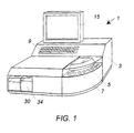
- Testing machine 1 comprises housing 3 having a mounting means and transport means such as rotatable loading wheel 5 having recesses 7 to receive elongate columns 2 (seen in Fig. 2 and described in greater detail below).
- Loading wheel 5 allows a plurality of columns 2 to be loaded into testing machine 2 and transported to stations within testing machine 1 for testing of a fluid sample.
- Other suitable mounting means and transport means may include. for example, a conveyor track or belt or a movable gripping arm which can move an elongate column between stations in testing machine 1.
- Other suitable mounting and transport means will become readily apparent to those skilled in the art, given the benefit of this disclosure.
- testing machine 1 has a control panel 9 to receive information, such as information read from bar code labels or keyed data, and a monitor 15 to display operating information, such as the results of testing.
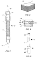
- a multi layer testing column 2 seen in Fig. 2, is contained within housing 3.
- Testing column 2 comprises elongate, cylindrical chamber or housing 4 having a longitudinal axis L and containing a plurality of membrane layers 6.
- a reservoir 8 is positioned above the membrane layers 6.
- Aperture 10 is formed at the upper end of housing 4.
- Aperture 12 is formed at the lower end of housing 4.
- a pipette adapter 11 is connected to the upper end of housing 4.
- membrane layers 6 are preferably formed by stacking a plurality of sheets of filter-like microporous membrane or fiber matrix membranes.
- Stacked membranes refer to a plurality of membranes placed in overlapping fashion. It is to be appreciated that the membranes may be offset with respect to one another, and that the membrane layers may be spaced from one another. for example, by spacer layers.
- a filter-like microporous membrane as used herein.
- a fiber matrix membrane refers to a membrane formed of a mat of fibers. preferably a fabric, which provides solid support for an anti-analyte, and has a plurality of pores which allow sample fluid to flow through the membrane and provide increased surface area for attachment of the anti-analyte as well as an increased number of sites for binding of analyte to anti-analyte.
- the membrane layers are preferably transparent to light and in general should be stackable in a chamber.
- Suitable materials for membrane layer 6 include cellulose. nitrocellulose, acrylic copolymer, polyethersulphone, polyethylene. polyvinylidene fluoride, polymer, nylon, plastic, and glass.
- Analyte refers to a substance present in a fluid sample and is sometimes referred to herein as a target analyte or target material.
- exemplary analytes include antibodies, antigens, ligands, ligand receptors, other proteins, and nucleic acids. Other suitable analytes will become readily apparent to those skilled in the art, given the benefit of this disclosure.
- Antianalyte refers to a substance which reacts specifically with an analyte present in a fluid sample or to which an analyte in a fluid sample binds.
- anti-analytes include antibodies, antigens, ligands, ligand receptors, aptamers, nucleic acids capable of hybridizing to an analyte nucleic acid, enzyme-linked immunosorbent analyte proteins or fragments or proteins capable of forming a complex with an analyte protein or protein fragment. and chemical compounds capable of having biological activity with a target analyte.
- suitable anti-analytes will become readily apparent to those skilled in the art, given the benefit of this disclosure.
- Corresponding analyte and anti-analyte pairs include, for example:
- antibodies, or fragments of antibodies can bind to an antigen or fragment of an antigen, e.g., a target protein. lipid. amino acid. phosphate group, carbohydrate, etc.
- an antigen or fragment of an antigen e.g., a target protein. lipid. amino acid. phosphate group, carbohydrate, etc.
- typically a target nucleic acid for example, from a blood cell, would first he extracted from the blood cell by any of several known techniques. It is possible. for example, to sonicate a sample or subject it to a detergent or organic extraction. The resulting lysate would then be injected into a multi-layer testing column. Such lysate may or may not still contain cell wall material and other cell debris.
- preferred embodiments of the multi-layer testing column of the invention employ filter layers to filter out such debris from the fluid sample which has been injected or otherwise fed into the multi-layer testing column.
- At least some sheets are coated with an anti-analyte to serve as a solid-phase substrate.
- Attachment of the anti-analyte to the substrate may be carried out by any conventional procedure, such as, for example, absorption or covalent bonding.
- a membrane surface can be chemically treated and certain anti-analytes may be chemically linked to the substrate.
- Chemical compounds can be directly synthesized on a membrane. These procedures are well known in the art, and no further details in these respects are deemed necessary for a complete understanding of the invention.
- the anti-analyte is biologically active.
- the anti-analyte attaches to membrane layer 6 and provide sites to which analyte of a fluid sample binds.
- the anti-analyte coating membrane layers 6 preferably provides specific binding sites. Specific binding sites, as used herein, refer to sites to which a specific analyte or class of analytes bind.
- the membrane layer 6 is then treated with a blocking substance or reagent to substantially block the non-specific binding sites on the membrane layer.
- the blocking reagent may be, e.g., bovine serum albumen (BSA).
- each membrane layer 6 preferably comprises a plurality of sub-layers, specifically, a shielding layer formed of a light absorption layer 14 and a first light reflective layer 16 below absorption layer 14; a capture layer 18 to which the coated anti-analyte attaches: and a second shielding layer formed of a second reflective layer 20 below capture layer 18 and a second absorption layer 21 below second reflective layer 20.
- Each shielding layer may, in certain preferred embodiments, act as a shielding layer for capture layers both above and below the shielding layer.
- Capture layer 18 is substantially transparent to at least certain wavelengths of light.
- the uppermost and lowermost membrane layers 6 in housing 4 are preferably filter layers which substantially prevent passage of large particles. e.g. blood cells, to other membrane layers 6 in housing 4. They do not. however. filter or block the flow of other, smaller sample analytes, e.g., antibodies. etc., which are passed to the lower membrane layers for binding.
- Certain membrane layers 6 may be treated only with a blocking substance or reagent to substantially block non-specific binding sites and serve as negative control layers. Negative control layers, under normal operating conditions, produce substantially no emitted light. If substantial light is emitted from a negative control layer, it is an indication that a problem exists within column 2. Other membrane layers 6 may be coated specifically to act as positive control layers. A positive control layer, under normal operating conditions, produces an emitted light. Thus, if conditions are other than normal, there will be substantially no emitted light from the positive control layer, indicating that a problem exists within column 2.
- control layers can be used, for example, as a reference to quantify the amount of the analyte in the sample by comparing the magnitude of the light or signal generated by the control layer to the magnitude of the light or signal generated by the capture layer. This relationship works when the magnitude of the signal is established for a known quantity of analyte.
- the control layers can also be used to identify faulty label and/or reagent, to indicate contamination of column 2, or serve as positional markers between membrane layers 6. For instance, in a column 2 having hundreds of stacked membrane layers 6, a control layer could be positioned between every ten membrane layers 6. reducing the chance of accumulated error which could occur in incorrectly identifying a particular membrane layer within a long string of adjacent membrane layers.
- Housing 4 is preferably filled with a buffer solution to stabilize the coated membrane layers.
- a buffer solution to stabilize the coated membrane layers.
- the buffer solution is removed from housing 4 prior to use.
- Suitable buffer solutions include, e.g.. phosphate buffers supplemented with BSA.
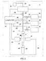
- a sample reservoir 25 is connected by control valve 23 and conduit 28 into column 2.
- Sample reservoir 25 may be, in certain preferred embodiments.
- a fluid sample container such as a test tube, typically used for collecting a fluid sample, e.g., patient's blood.
- a fluid sample container or test tube may be housed in a mounting means such as the recesses 7 of loading wheel 5 described above. Fluid sample can be removed from a test tube and inserted in a multi-layer column 2 by known fluid delivery means.
- Exemplary fluid delivery means include, for example, a vacuum based pipette tip or sampling needle which is connected to a pipette adapter and inserted into a test tube to draw fluid from the test tube; a movable arm to move the needle to a multi-layer column 2; and a pressure source to force fluid sample from the needle into the first aperture 10 of the housing 4 of multi-layer column 2.
- a vacuum based pipette tip or sampling needle which is connected to a pipette adapter and inserted into a test tube to draw fluid from the test tube
- a movable arm to move the needle to a multi-layer column 2
- a pressure source to force fluid sample from the needle into the first aperture 10 of the housing 4 of multi-layer column 2.
- a loading wheel 5 may be provided for handling multi-layer columns 2 and a separate loading wheel 5 may be provided for handling test tubes or other containers of fluid sample.
- a single, or multiple loading wheels 5 may be used to transport a combination of multi-layer columns 2 and fluid sample containers between different stations within testing machine 1.
- Exemplary stations within testing machine 1 include a fluid handling station where fluid sample is taken from a fluid sample container and transferred to a multi-layer column, a reagent station where reagent is added to the multi-layer column, a washing station where wash buffer is added to the multi-layer column to remove unbound analyte and/or other particles, and a sensing station where light or another signal from multi-layer column 2 is received.
- multiple processing steps can be performed at a single station.
- An air reservoir 24 is connected by control valve 26 and conduit 28 to column 2.
- Wash buffer reservoir 30 is connected by control valve 32 and conduit 28 to column 2.
- Reagent reservoir 34 is connected by control valve 36 and conduit 28 to column 2.
- a sensor is used to receive a signal from column 2 and generate a corresponding electrical signal.
- the sensor comprises a light source 38 and a light sensor 40.
- An excitation energy source is provided in certain preferred embodiments to direct excitation energy toward column 2 to generate a signal from column 2.
- the energy source is light source 38.
- the excitation energy source may, in certain preferred embodiments, apply a voltage differential across the elongate column via a pair of electrodes, not shown. Other suitable excitation energy sources will become readily apparent to those skilled in the art, given the benefit of this disclosure.
- Light source 38 is positioned adjacent column 2 with light sensor 40 positioned adjacent column 2, opposite light source 38.
- Light sensor 40 is connected by cable 42 to computer 44 located in housing 3.
- Reservoirs 25, 24, 30, 34 serve to provide containment for a suitable volume of sample, air, wash buffer or reagent.
- the reservoirs contain enough sample. air. wash buffer or reagent for a single test, and, more preferably, are sized to contain enough for multiple tests.
- the reservoirs provide a supply of at least a portion of their contents which can be fed through a conduit, which is optionally regulated by a control valve, to column 2. Suitable reservoirs will become readily apparent to those skilled in the art. given the benefit of this disclosure.
- Waste reservoir or bin 46 is positioned below column 2 to receive outflow from aperture 12. In certain preferred embodiments, as seen in Fig. 6. waste bin 46 is directly connected to the lower end of housing 4 with collar 48. Channels 50 are formed in collar 48 to allow the passage of air into and out of column 2.
- a sample for example, a blood sample. is introduced into column 2 from sample reservoir 25. Air is introduced into column 2 from air reservoir 24 through conduit 28. Pump 52 is connected to air reservoir 24 by conduit 54 to vary the air pressure in reservoir 24. The air pressure in column 2 is varied alternately from a positive value to a vacuum, causing the sample to flow up and down through membrane layers 6.
- the flow rate of the sample through column 2 is controlled in order to enhance its binding efficiency. Binding is also increased due to the fact that the probability of analytes in the sample encountering binding sites on capture layer 18 is increased with multiple passes of the sample through column 2.
- Wash buffer from reservoir 30 may be then introduced into column 2 to remove or wash unbound analytes from column 2 out through aperture 12 into waste bin 46.
- Reagent from reservoir 34 is then introduced into column 2.
- the reagent e.g.. a second antibody
- the labeled reagent is bound to the captured analytes by passing the labeled reagent through column 2 in a similar manner described above with respect to the sample. The flow of reagent through the chamber is, therefore, also controlled to enhance its binding efficiency. Wash buffer may be introduced again to wash out any unbound labeled reagent.
- the reagent has a radioactive label.
- a sensor is employed to detect the radiation emanating from particular membrane layers 6. It is apparent that any such sensor should be sensitive enough to distinguish between the radiation emanating from different membrane layers 6.
- the reagent has a fluorescent label, in which case another light source is required for the labeled reagent to emit light.
- light source 38 is used to project light, e.g., a laser light of a specific wavelength, into column 2 to excite the bound, labeled reagent to produce an emitted light.
- capture layer 18 emits light having a specific wavelength.
- Light sensor 40 scans each membrane layer 6 in column 2, detecting the location of each of the captured layers based on the wavelength of its emitted light, in bar code reader fashion. A signal is then transmitted from light sensor 40 through cable 42 to computer 44 for analysis. With the labeled reagent bound to the captured analyte, light sensor 40 and computer 44 are able to detect the presence and quantity of different captured analytes on different membrane layers 6.
- the reagent may have an electrochemiluminescent label. in which case a voltage is applied to column 2, resulting in emitted light of a specific wavelength from the bound, labeled reagent present on capture layers 18 of membrane layers 6.
- the label may be formed of two portions, the first portion being attached to the anti-analyte on capture layer 18, the second portion being conjugated to the reagent.
- the label will only emit light when the first and second portions are sufficiently close to one another.
- An example of a suitable first portion is europium cryptate.
- An example of a suitable second portion is allophycocyanin. If a analyte in the sample has bound to capture layer 18 and the reagent has in turn bound to the sample analyte, the first and second portions will be close enough to create emitted light of a specific wavelength. As described above, the light may be emitted directly, or require another light source or applied voltage in order to create the emitted light. Accordingly, the presence of the analyte will be identified by the emitted light.
- the wash buffer and reagent can be added to column 2 manually rather than from reservoirs controlled by valves and/or a computer or other suitable controller.
- sample can be added to column 2 in a manual basis, or under control of a computer or other suitable controller.
- a multi-layer testing apparatus in accordance with the present invention can be used, for example, to analyze blood samples and to screen chemical compounds in search of biological activity for drug discovery.
- Tests that can be run on a blood sample using the present invention include, for example, tests screening for viruses, antigens, antibodies, proteins, enzymes, etc., in the blood, such as screening for Hepatitis B Surface Antigen (HbsAg), Hepatitis C Antibody (HCV), and HIV.
- Chemical compounds can be synthesized directly on a membrane. Then. multi-layer columns can be assembled and used to screen biological activity of the compounds with a target protein related to a disease present in a test fluid sample. By having multiple distinct layers, multiple tests can be done on a single fluid sample simultaneously. increasing productivity, throughput and reducing costs.
- the number of layers of membrane 6 may be in the tens, hundreds. thousands or more.
- microporous membrane layer provides a larger surface area than that of a microplate, and, therefore. the sensitivity of the testing is greatly increased since the sensitivity is proportional to the capture surface. Sensitivity can also be increased through the use of labels such as chemiluminescent labels.
- the present invention is suitable for use in multiple step processes, e.g., two step processes.
- a two step process is an enzyme-linked immunosorbent assay (ELISA).
- ELISA enzyme-linked immunosorbent assay
- an anti-analyte is attached to a capture layer of a multi-layer column such as described above in connection with Figs. 3, 4.
- the column is then exposed to a sample, e.g., a patient's blood, such that analyte within the sample can bind to the anti-analyte.
- the column is then washed with a buffer to remove unbound analyte, using, e.g., in the embodiment described above, buffer solution from wash buffer reservoir 30.
- the column is then exposed to a reagent, e.g., from reagent reservoir 34, carrying the same or different anti-analyte as that coated on the capture layer, which specifically binds with the analyte.
- the reagent is labeled with a detectable moiety. Detectable moieties, include, for example, enzyme labels, radioactive labels, fluorescent labels, and chemilluminescent labels which are bound to the reagent.
- the column may be washed again, using, for example, a buffer solution such as wash buffer from wash buffer reservoir 30.
- a sensor is then used to detect the presence and/or quantity of analyte in the sample in the manner described above.
- a programmable control system e.g., a general purpose computer with suitable control software or a dedicated computer module within housing 3 may be used to automatically control testing machine 1 and its components.
- computer 44 may be used to control operation of valves 23, 26, 32, and 36 through cables 55, 56, 58, and 60, respectively.
- Computer 44 may also be used to control operation of light source 38 through cable 62. It will be within the ability of those skilled in the art to provide suitable control software and hardware for controlling testing machine 1.
- a centrifuge device can be included within housing 3 to provide force to generate flow of sample through multi-layer membranes of a multi-layer column.
- testing machine 1 has a temperature controlling device.
- a temperature controlling means heats and/or cools a multi-layer column. It is to be appreciated that the temperature of the multi-layer column may be controlled directly, such as with a temperature sensor detecting the temperature of the multi-layer column and maintaining a desired setpoint temperature. Alternatively, the temperature of the multi-layer column could be controlled indirectly by sensing and controlling the temperature in an area housing the multi-layer column. Temperature controlling means may include a heating element and may also include a cooling device. Other suitable temperature controlling means will become readily apparent to those skilled in the art. given the benefit of this disclosure.
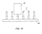
- a series of columns 2 or fluid sample containers can be carried by a conveyor track or belt 90 (represented schematically here) or the like between different stations within testing machine to test separate samples of the same or different fluids.
- Other means for transporting multi-layer columns 2 and fluid sample containers include, for example, movable arms which can grip and hold columns 2 and the fluid sample containers.
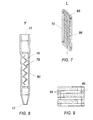
- Membrane layers 66 are formed on a single planar substrate 68 by coating different segments of the planar substrate 68 with different anti-analytes in a known manner.
- Planar substrate 68 is placed in housing 70 such that the plane of substrate 68 is substantially parallel to a longitudinal axis L of housing 70.
- Housing 70 is used in a testing apparatus as described above.
- Membrane layers 66 may be marked with a dye to differentiate one membrane layer 66 from another.
- the specific antigens or antibodies of the membrane layers may be placed directly on the inner surface of housing 70, which then serves as the substrate.
- FIG. 8 Another preferred embodiment is shown in Fig. 8, where membrane layers 76 are formed on a substrate 78.
- Substrate 78 is folded in accordion fashion within housing 80.
- Each membrane layer 76 is. therefore. at an oblique angle with respect to a longitudinal axis Y of housing 80.
- the multi-layer testing apparatus of Fig. 7 is used in a testing apparatus as described above. It is to be appreciated that in certain preferred embodiments, membrane layers 76 at the top and bottom of substrate 78 may act as filter layers as described above.
- FIG. 9 Another preferred embodiment is shown in Fig. 9, where a portion 86 of each membrane layer 88 is cut away, each portion 86 at least partially overlapping adjacent portions 86 such that a channel is formed through membrane layers 88 through which fluid sample may directly flow.
Landscapes
- Health & Medical Sciences (AREA)
- Immunology (AREA)
- Life Sciences & Earth Sciences (AREA)
- Chemical & Material Sciences (AREA)
- Engineering & Computer Science (AREA)
- General Health & Medical Sciences (AREA)
- Molecular Biology (AREA)
- General Physics & Mathematics (AREA)
- Biochemistry (AREA)
- Pathology (AREA)
- Analytical Chemistry (AREA)
- Biomedical Technology (AREA)
- Physics & Mathematics (AREA)
- Urology & Nephrology (AREA)
- Hematology (AREA)
- Biotechnology (AREA)
- Microbiology (AREA)
- Cell Biology (AREA)
- Food Science & Technology (AREA)
- Medicinal Chemistry (AREA)
- Automatic Analysis And Handling Materials Therefor (AREA)
- Investigating Or Analysing Biological Materials (AREA)
- Materials For Medical Uses (AREA)
- Memory System Of A Hierarchy Structure (AREA)
- Prostheses (AREA)
- Apparatus Associated With Microorganisms And Enzymes (AREA)
Claims (23)
- Säule mit mehreren Lagen, die in Kombination aufweist:eine Kammer mit einer Längsachse mit einem ersten Ende, das eine erste Öffnung aufweist; undeine Vielzahl von vertikal gestapelten, im wesentlichen ebenen filterartigen mikroporösen Membranlagen, die innerhalb der Kammer gestapelt sind, die mindestens eine Vielzahl von Trägermaterialien in fester Phase umfaßen, wobei jedes ein unterschiedliches Antianalyt trägt, und wobei jede Membranlage eine Vielzahl von Poren aufweist, die den Fluß eines Probefluids durch jede Membranlage gestatten, und was gestattet, daß das Probefluid durch die Vielzahl der vertikal gestapelten Membranlagen fließt, wobei die Ebene einer jeden der Membanlagen im wesentlichen senkrecht zur Längsachse der Kammer verläuft.
- Säule mit mehreren Lagen nach Anspruch 1, bei der eine jede der Membranlagen eine Fasergrundmassemembran aufweist.
- Säule mit mehreren Lagen nach Anspruch 1, bei der die Membranlagen im wesentlichen lichtdurchlässig bei mindestens einer ausgewählten Wellenlänge sind.
- Säule mit mehreren Lagen nach Anspruch 1, bei der eine jede der Vielzahl der Membranlagen eine Einfanglage, die ein Antianalyt trägt, und mindestens eine lichtabschirmende Lage im wesentlichen koplanar mit der Einfanglage aufweist.
- Säule mit mehreren .Lagen nach Anspruch 4, bei der mindestens eine der lichtabschirmenden Lagen eine Lichtabsorptionsunterlage umfaßt.
- Säule mit mehreren Lagen nach Anspruch 4, bei der mindestens eine der lichtabschirmenden Lagen eine Lichtreflexionsunterlage umfaßt.
- Säule mit mehreren Lagen nach Anspruch 1, bei der mindestens eine Vielzahl von Trägermaterialien in fester Phase eine Blockierungssubstanz trägt.
- Säule mit mehreren Lagen nach Anspruch 1, bei der im wesentlichen alle Flächen innerhalb der Kammer eine Blockierungssubstanz tragen.
- Säule mit mehreren Lagen nach Anspruch 1, bei der die hintersten Membranlagen der Vielzahl von Membranlagen Filterlagen mit Poren sind, die so bemessen sind, daß sie im wesentlichen den Fluß von Teilchen mit einer vorgewählten Größe zu den mittleren Membranlagen der Vielzahl von Membranlagen verhindern.
- Säule mit mehreren Lagen nach Anspruch 1, bei der die Membranlagen axial voneinander längs der Längsachse beabstandet sind.
- Säule mit mehreren Lagen nach Anspruch 1, die außerdem eine Pufferlösung aufweist, die innerhalb der Kammer enthalten ist.
- Säule mit mehreren Lagen nach Anspruch 1, bei der die Kammer eine zweite Öffnung an einem zweiten Ende davon aufweist.
- Säule mit mehreren Lagen nach Anspruch 12, die außerdem einen Abproduktbehälter in Fluidverbindung mit der zweiten Öffnung der Kammer aufweist.
- Säule mit mehreren Lagen nach Anspruch 1, die außerdem eine Fluidflußöffnung aufweist, um einen Fluidaustrittsflußweg aus der Kammer heraus bereitzustellen.
- Säule mit mehreren Lagen nach Anspruch 1, bei der ein jeder der Antianalyte aus der Gruppe ausgewählt wird, die besteht aus: Antikörpern; Antigenen; Liganden; Ligandenrezeptoren; Nukleinsäuren, die an einer Analyt-Nukleinsäure hybridisieren können; enzymverbundenes Immunosorbens-Analyt; Proteine oder Bruchstücke von Proteinen, die in der Lage sind, einen Komplex mit einem Analyt-Protein oder Protein-Bruchstück zu bilden; und chemische Verbindungen, die in der Lage sind, eine biologische Aktivität mit einem Target-Analyt zu zeigen.
- Fluidtestvorrichtung, die in Kombination aufweist:ein Gehäuse;eine Montageeinrichtung innerhalb des Gehäuses, um eine längliche Kammer aufzunehmen;eine längliche Kammer, die in der Montageeinrichtung montiert ist, die eine erste Öffnung in einem ersten Ende davon und eine Vielzahl von vertikal gestapelten, im wesentlichen ebenen filterartigen mikroporösen Membranlagen aufweist, die innerhalb der Kammer gestapelt sind, die mindestens eine Vielzahl von Trägermaterialien in fester Phase umfaßen, wobei jedes ein unterschiedliches Antianalyt trägt, und wobei jede Membranlage eine Vielzahl von Poren aufweist, die den Fluß eines Probefluids durch jede Membranlage gestatten, und was gestattet, daß das Probefluid durch die Vielzahl der vertikal gestapelten Membranlagen fließt, wobei die Ebene einer jeden der Membanlagen im wesentlichen senkrecht zur Längsachse der Kammer verläuft;einen Reagensbehälter und eine Fluidliefereinrichtung innerhalb des Gehäuses, um ein Reagens aus dem Reagensbehälter zur ersten Öffnung der länglichen Kammer zuzuführen;einen Waschpufferbehälter und eine zweite Fluidliefereinrichtung innerhalb des Gehäuses, um den Waschpuffer aus dem Waschpufferbehälter zur ersten Öffnung der länglichen Kammer zuzuführen; undeinen Sensor innerhalb des Gehäuses, um ein Signal von der länglichen Kammer zu empfangen, und um ein entsprechendes elektrisches Signal zu erzeugen.
- Fluidtestvorrichtung nach Anspruch 16, die außerdem einen Computer aufweist, der auf das elektrische Signal anspricht, das vom Sensor erzeugt wird.
- Fluidtestvorrichtung nach Anspruch 16, die außerdem ein Fluidtransportsystem aufweist, das eine Fluidprobenbehältermontageeinrichtung, um mindestens einen Behälter mit der Fluidprobe zu montieren, und eine Fluidprobenliefereinrichtung aufweist, um die Fluidprobe vom Behälter mit der Fluidprobe zu einer länglichen Kammer zuzuführen, die in der Montageeinrichtung montiert ist.
- Fluidtestvorrichtung nach Anspruch 18, bei der die Fluidprobenbehältermontageeinrichtung gleichzeitig eine Vielzahl von Behältern mit der Fluidprobe hält, und bei der die Fluidprobenliefereinrichtung so angepaßt ist, daß sie aufeinanderfolgend die Fluidprobe von jedem der Behälter mit der Fluidprobe zu einer entsprechenden länglichen Kammer zuführt.
- Fluidtestvorrichtung nach Anspruch 16, die außerdem eine Erregungsenergiequelle innerhalb des Gehäuses aufweist, um Erregungsenergie in Richtung der länglichen Kammer zu lenken.
- Fluidtestvorrichtung nach Anspruch 20, bei der die Erregungsenergiequelle eine Lichtquelle aufweist, die ausgerichtet ist, um mindestens eine der Membranlagen in der länglichen Säule mit Licht von einer vorgewählten Wellenlänge zu beleuchten, worin mindestens eine der Membranlagen in der länglichen Kammer auf die vorgewählte Wellenlänge anspricht.
- Fluidtestvorrichtung nach Anspruch 20, bei der die Erregungsenergiequelle ein Spannungsdifferential über die längliche Kammer anlegt.
- Fluidtestvorrichtung nach Anspruch 16, die außerdem eine regelbare Druckquelle aufweist, die funktionell mit der ersten Öffnung verbunden ist.
Applications Claiming Priority (3)
| Application Number | Priority Date | Filing Date | Title |
|---|---|---|---|
| US9046998P | 1998-06-24 | 1998-06-24 | |
| US90469P | 1998-06-24 | ||
| PCT/US1999/014118 WO1999067647A1 (en) | 1998-06-24 | 1999-06-23 | Multi-layer testing column |
Publications (2)
| Publication Number | Publication Date |
|---|---|
| EP1004025A1 EP1004025A1 (de) | 2000-05-31 |
| EP1004025B1 true EP1004025B1 (de) | 2004-01-14 |
Family
ID=22222904
Family Applications (1)
| Application Number | Title | Priority Date | Filing Date |
|---|---|---|---|
| EP99931860A Expired - Lifetime EP1004025B1 (de) | 1998-06-24 | 1999-06-23 | Testsäule mit mehreren lagen |
Country Status (10)
| Country | Link |
|---|---|
| US (1) | US20040105782A1 (de) |
| EP (1) | EP1004025B1 (de) |
| JP (1) | JP2002519643A (de) |
| CN (1) | CN1158530C (de) |
| AT (1) | ATE257944T1 (de) |
| AU (1) | AU4827999A (de) |
| CA (1) | CA2301077C (de) |
| DE (1) | DE69914164T2 (de) |
| ES (1) | ES2214865T3 (de) |
| WO (1) | WO1999067647A1 (de) |
Cited By (1)
| Publication number | Priority date | Publication date | Assignee | Title |
|---|---|---|---|---|
| WO2015048769A1 (en) * | 2013-09-30 | 2015-04-02 | Board Of Regents, The University Of Texas System | Method and apparatus for scanning detection |
Families Citing this family (24)
| Publication number | Priority date | Publication date | Assignee | Title |
|---|---|---|---|---|
| US7799521B2 (en) * | 1998-06-24 | 2010-09-21 | Chen & Chen, Llc | Thermal cycling |
| US6780617B2 (en) | 2000-12-29 | 2004-08-24 | Chen & Chen, Llc | Sample processing device and method |
| US20030032029A1 (en) * | 1998-12-21 | 2003-02-13 | Nanogen, Inc. | Three dimensional apparatus and method for integrating sample preparation and multiplex assays |
| US7214477B1 (en) | 1999-07-26 | 2007-05-08 | The United States Of America As Represented By The Secretary Of The Department Of Health And Human Services | Layered device with capture regions for cellular analysis |
| EP1218743B1 (de) * | 1999-07-26 | 2006-05-31 | THE GOVERNMENT OF THE UNITED STATES OF AMERICA, as represented by THE SECRETARY, DEPARTMENT OF HEALTH AND HUMAN SERVICES | Schichtvorrichtung mit einfangbereichen zur zellulären analyse |
| CA2438137A1 (en) * | 2001-02-13 | 2002-08-22 | Universiteit Gent | Device and method for detecting the presence of an analyte |
| JP4513085B2 (ja) | 2001-09-11 | 2010-07-28 | アイキューム インク | 試料の容器 |
| US20060147926A1 (en) | 2002-11-25 | 2006-07-06 | Emmert-Buck Michael R | Method and apparatus for performing multiple simultaneous manipulations of biomolecules in a two-dimensional array |
| JP4632262B2 (ja) | 2003-02-05 | 2011-02-16 | アイキューム,インク. | サンプルの処理 |
| US20070017870A1 (en) | 2003-09-30 | 2007-01-25 | Belov Yuri P | Multicapillary device for sample preparation |
| WO2005121963A2 (en) * | 2004-06-07 | 2005-12-22 | Iquum, Inc. | Sample multiprocessing |
| DE102005005437A1 (de) * | 2005-02-05 | 2006-08-10 | Eppendorf Ag | Filterpipettenspitze |
| US20080003564A1 (en) * | 2006-02-14 | 2008-01-03 | Iquum, Inc. | Sample processing |
| GB2435510A (en) | 2006-02-23 | 2007-08-29 | Mologic Ltd | Enzyme detection product and methods |
| GB2435511A (en) | 2006-02-23 | 2007-08-29 | Mologic Ltd | Protease detection |
| GB2435512A (en) | 2006-02-23 | 2007-08-29 | Mologic Ltd | A binding assay and assay device |
| CA2644855C (en) * | 2006-03-09 | 2019-11-19 | Aethlon Medical, Inc. | Extracorporeal removal of microvesicular particles |
| CN101467036B (zh) | 2006-06-06 | 2013-06-19 | 霍夫曼-拉罗奇有限公司 | 全血样品的差异溶血 |
| US20080113357A1 (en) * | 2006-06-29 | 2008-05-15 | Millipore Corporation | Filter device for the isolation of a nucleic acid |
| JP4935424B2 (ja) * | 2007-02-28 | 2012-05-23 | 東レ株式会社 | 免疫分析チップ |
| US20110107855A1 (en) * | 2008-03-28 | 2011-05-12 | Pelican Group Holdings, Inc. | Sample preparation devices and methods for processing analytes |
| CN102841167A (zh) * | 2011-06-20 | 2012-12-26 | 苏州赛分科技有限公司 | 一种液相吸附色谱分离柱 |
| US11260386B2 (en) | 2015-06-05 | 2022-03-01 | The Emerther Company | Component of a device, a device, and a method for purifying and testing biomolecules from biological samples |
| US10591477B2 (en) * | 2016-07-25 | 2020-03-17 | Bio-Rad Laboratories, Inc. | Lateral flow device and method of use |
Family Cites Families (6)
| Publication number | Priority date | Publication date | Assignee | Title |
|---|---|---|---|---|
| DE2942674B1 (de) * | 1979-10-23 | 1981-05-07 | Drägerwerk AG, 2400 Lübeck | Pruefroehrchen zur Messung von Nickel-Aerosolen |
| EP0139373A1 (de) * | 1983-08-26 | 1985-05-02 | The Regents Of The University Of California | System für vielfache Immunoassays |
| US5057438A (en) * | 1986-09-24 | 1991-10-15 | Agency Of Industrial Science And Technology | Electrophoretic antigen-antibody determination with laminate of multiple membranes |
| US4874691A (en) * | 1987-10-16 | 1989-10-17 | Quadra Logic Technologies Inc. | Membrane-supported immunoassays |
| US5438128A (en) * | 1992-02-07 | 1995-08-01 | Millipore Corporation | Method for rapid purifiction of nucleic acids using layered ion-exchange membranes |
| AU6360994A (en) * | 1993-03-08 | 1994-09-26 | Steven H Boyd | Aligned fiber diagnostic chromatography |
-
1999
- 1999-06-23 EP EP99931860A patent/EP1004025B1/de not_active Expired - Lifetime
- 1999-06-23 WO PCT/US1999/014118 patent/WO1999067647A1/en active IP Right Grant
- 1999-06-23 AU AU48279/99A patent/AU4827999A/en not_active Abandoned
- 1999-06-23 DE DE69914164T patent/DE69914164T2/de not_active Expired - Lifetime
- 1999-06-23 ES ES99931860T patent/ES2214865T3/es not_active Expired - Lifetime
- 1999-06-23 JP JP2000556253A patent/JP2002519643A/ja active Pending
- 1999-06-23 CN CNB998010111A patent/CN1158530C/zh not_active Expired - Lifetime
- 1999-06-23 AT AT99931860T patent/ATE257944T1/de not_active IP Right Cessation
- 1999-06-23 CA CA2301077A patent/CA2301077C/en not_active Expired - Lifetime
-
2003
- 2003-09-30 US US10/605,459 patent/US20040105782A1/en not_active Abandoned
Cited By (3)
| Publication number | Priority date | Publication date | Assignee | Title |
|---|---|---|---|---|
| WO2015048769A1 (en) * | 2013-09-30 | 2015-04-02 | Board Of Regents, The University Of Texas System | Method and apparatus for scanning detection |
| CN105593677A (zh) * | 2013-09-30 | 2016-05-18 | 得克萨斯大学体系董事会 | 用于扫描检测的方法和设备 |
| US9482611B2 (en) | 2013-09-30 | 2016-11-01 | Board Of Regents, The University Of Texas System | Method and apparatus for scanning detection |
Also Published As
| Publication number | Publication date |
|---|---|
| EP1004025A1 (de) | 2000-05-31 |
| ATE257944T1 (de) | 2004-01-15 |
| CN1273638A (zh) | 2000-11-15 |
| CA2301077C (en) | 2010-05-25 |
| JP2002519643A (ja) | 2002-07-02 |
| US20040105782A1 (en) | 2004-06-03 |
| ES2214865T3 (es) | 2004-09-16 |
| WO1999067647A1 (en) | 1999-12-29 |
| CA2301077A1 (en) | 1999-12-29 |
| CN1158530C (zh) | 2004-07-21 |
| AU4827999A (en) | 2000-01-10 |
| DE69914164D1 (de) | 2004-02-19 |
| DE69914164T2 (de) | 2004-11-25 |
Similar Documents
| Publication | Publication Date | Title |
|---|---|---|
| EP1004025B1 (de) | Testsäule mit mehreren lagen | |
| US11940385B2 (en) | Apparatus for conducting continuous interleaved assaying in a multi-well plate | |
| JP3521144B2 (ja) | 自動連続ランダム・アクセス分析システムおよびその構成要素 | |
| US6136549A (en) | systems and methods for performing magnetic chromatography assays | |
| AU2003228711B2 (en) | Method and system for the detection of cardiac risk factors | |
| JP3464793B2 (ja) | 自動連続ランダムアクセス分析システムおよびその構成要素 | |
| US20060019407A1 (en) | Immunoassay assembly and methods of use | |
| US20060292558A1 (en) | Methods and apparatus for protein assay diagnostics | |
| JP2014002143A (ja) | 臨床診断装置用の側方流動アッセイ装置及びそれに関する臨床診断装置の構成 | |
| US20020025583A1 (en) | Analytical rotor and method for detecting analytes in liquid samples | |
| US20070292844A1 (en) | Enhanced biohazard detection system | |
| AU720420B2 (en) | Assay apparatus | |
| MXPA00001785A (en) | Multi-layer testing column | |
| US20080230605A1 (en) | Process and apparatus for maintaining data integrity | |
| JP2001512834A (ja) | 複数検出器を有する検定装置 | |
| US20240069024A1 (en) | Diagnostic assay methods using assay device having microreactor | |
| JP7161851B2 (ja) | 免疫測定装置の状態確認方法および免疫測定装置 |
Legal Events
| Date | Code | Title | Description |
|---|---|---|---|
| PUAI | Public reference made under article 153(3) epc to a published international application that has entered the european phase |
Free format text: ORIGINAL CODE: 0009012 |
|
| 17P | Request for examination filed |
Effective date: 20000309 |
|
| AK | Designated contracting states |
Kind code of ref document: A1 Designated state(s): AT BE CH CY DE DK ES FI FR GB GR IE IT LI LU MC NL PT SE |
|
| 17Q | First examination report despatched |
Effective date: 20010516 |
|
| GRAH | Despatch of communication of intention to grant a patent |
Free format text: ORIGINAL CODE: EPIDOS IGRA |
|
| GRAS | Grant fee paid |
Free format text: ORIGINAL CODE: EPIDOSNIGR3 |
|
| GRAA | (expected) grant |
Free format text: ORIGINAL CODE: 0009210 |
|
| AK | Designated contracting states |
Kind code of ref document: B1 Designated state(s): AT BE CH CY DE DK ES FI FR GB GR IE IT LI LU MC NL PT SE |
|
| PG25 | Lapsed in a contracting state [announced via postgrant information from national office to epo] |
Ref country code: NL Free format text: LAPSE BECAUSE OF FAILURE TO SUBMIT A TRANSLATION OF THE DESCRIPTION OR TO PAY THE FEE WITHIN THE PRESCRIBED TIME-LIMIT Effective date: 20040114 Ref country code: LI Free format text: LAPSE BECAUSE OF FAILURE TO SUBMIT A TRANSLATION OF THE DESCRIPTION OR TO PAY THE FEE WITHIN THE PRESCRIBED TIME-LIMIT Effective date: 20040114 Ref country code: FI Free format text: LAPSE BECAUSE OF FAILURE TO SUBMIT A TRANSLATION OF THE DESCRIPTION OR TO PAY THE FEE WITHIN THE PRESCRIBED TIME-LIMIT Effective date: 20040114 Ref country code: CY Free format text: LAPSE BECAUSE OF FAILURE TO SUBMIT A TRANSLATION OF THE DESCRIPTION OR TO PAY THE FEE WITHIN THE PRESCRIBED TIME-LIMIT Effective date: 20040114 Ref country code: CH Free format text: LAPSE BECAUSE OF FAILURE TO SUBMIT A TRANSLATION OF THE DESCRIPTION OR TO PAY THE FEE WITHIN THE PRESCRIBED TIME-LIMIT Effective date: 20040114 Ref country code: BE Free format text: LAPSE BECAUSE OF FAILURE TO SUBMIT A TRANSLATION OF THE DESCRIPTION OR TO PAY THE FEE WITHIN THE PRESCRIBED TIME-LIMIT Effective date: 20040114 Ref country code: AT Free format text: LAPSE BECAUSE OF FAILURE TO SUBMIT A TRANSLATION OF THE DESCRIPTION OR TO PAY THE FEE WITHIN THE PRESCRIBED TIME-LIMIT Effective date: 20040114 |
|
| REG | Reference to a national code |
Ref country code: GB Ref legal event code: FG4D |
|
| REG | Reference to a national code |
Ref country code: CH Ref legal event code: EP |
|
| REG | Reference to a national code |
Ref country code: IE Ref legal event code: FG4D |
|
| REF | Corresponds to: |
Ref document number: 69914164 Country of ref document: DE Date of ref document: 20040219 Kind code of ref document: P |
|
| PG25 | Lapsed in a contracting state [announced via postgrant information from national office to epo] |
Ref country code: SE Free format text: LAPSE BECAUSE OF FAILURE TO SUBMIT A TRANSLATION OF THE DESCRIPTION OR TO PAY THE FEE WITHIN THE PRESCRIBED TIME-LIMIT Effective date: 20040414 Ref country code: GR Free format text: LAPSE BECAUSE OF FAILURE TO SUBMIT A TRANSLATION OF THE DESCRIPTION OR TO PAY THE FEE WITHIN THE PRESCRIBED TIME-LIMIT Effective date: 20040414 Ref country code: DK Free format text: LAPSE BECAUSE OF FAILURE TO SUBMIT A TRANSLATION OF THE DESCRIPTION OR TO PAY THE FEE WITHIN THE PRESCRIBED TIME-LIMIT Effective date: 20040414 |
|
| PG25 | Lapsed in a contracting state [announced via postgrant information from national office to epo] |
Ref country code: LU Free format text: LAPSE BECAUSE OF NON-PAYMENT OF DUE FEES Effective date: 20040623 Ref country code: IE Free format text: LAPSE BECAUSE OF NON-PAYMENT OF DUE FEES Effective date: 20040623 |
|
| PG25 | Lapsed in a contracting state [announced via postgrant information from national office to epo] |
Ref country code: MC Free format text: LAPSE BECAUSE OF NON-PAYMENT OF DUE FEES Effective date: 20040630 |
|
| NLV1 | Nl: lapsed or annulled due to failure to fulfill the requirements of art. 29p and 29m of the patents act | ||
| REG | Reference to a national code |
Ref country code: CH Ref legal event code: PL |
|
| REG | Reference to a national code |
Ref country code: ES Ref legal event code: FG2A Ref document number: 2214865 Country of ref document: ES Kind code of ref document: T3 |
|
| ET | Fr: translation filed | ||
| PLBE | No opposition filed within time limit |
Free format text: ORIGINAL CODE: 0009261 |
|
| STAA | Information on the status of an ep patent application or granted ep patent |
Free format text: STATUS: NO OPPOSITION FILED WITHIN TIME LIMIT |
|
| 26N | No opposition filed |
Effective date: 20041015 |
|
| REG | Reference to a national code |
Ref country code: IE Ref legal event code: MM4A |
|
| REG | Reference to a national code |
Ref country code: HK Ref legal event code: WD Ref document number: 1027625 Country of ref document: HK |
|
| PG25 | Lapsed in a contracting state [announced via postgrant information from national office to epo] |
Ref country code: PT Free format text: LAPSE BECAUSE OF NON-PAYMENT OF DUE FEES Effective date: 20040614 |
|
| REG | Reference to a national code |
Ref country code: DE Ref legal event code: R081 Ref document number: 69914164 Country of ref document: DE Owner name: ROCHE MOLECULAR SYSTEMS, INC. (N.D.GES.D. STAA, US Free format text: FORMER OWNER: CHEN & CHEN, LLC, BROOKLINE, MASS., US |
|
| REG | Reference to a national code |
Ref country code: FR Ref legal event code: PLFP Year of fee payment: 18 |
|
| REG | Reference to a national code |
Ref country code: GB Ref legal event code: 732E Free format text: REGISTERED BETWEEN 20160519 AND 20160525 |
|
| REG | Reference to a national code |
Ref country code: FR Ref legal event code: TP Owner name: ROCHE MOLECULAR SYSTEMS INC., US Effective date: 20160802 |
|
| REG | Reference to a national code |
Ref country code: FR Ref legal event code: PLFP Year of fee payment: 19 |
|
| REG | Reference to a national code |
Ref country code: FR Ref legal event code: PLFP Year of fee payment: 20 |
|
| PGFP | Annual fee paid to national office [announced via postgrant information from national office to epo] |
Ref country code: DE Payment date: 20180608 Year of fee payment: 20 |
|
| PGFP | Annual fee paid to national office [announced via postgrant information from national office to epo] |
Ref country code: FR Payment date: 20180516 Year of fee payment: 20 Ref country code: IT Payment date: 20180614 Year of fee payment: 20 |
|
| PGFP | Annual fee paid to national office [announced via postgrant information from national office to epo] |
Ref country code: GB Payment date: 20180403 Year of fee payment: 20 Ref country code: ES Payment date: 20180702 Year of fee payment: 20 |
|
| REG | Reference to a national code |
Ref country code: DE Ref legal event code: R071 Ref document number: 69914164 Country of ref document: DE |
|
| REG | Reference to a national code |
Ref country code: GB Ref legal event code: PE20 Expiry date: 20190622 |
|
| PG25 | Lapsed in a contracting state [announced via postgrant information from national office to epo] |
Ref country code: GB Free format text: LAPSE BECAUSE OF EXPIRATION OF PROTECTION Effective date: 20190622 |
|
| REG | Reference to a national code |
Ref country code: ES Ref legal event code: FD2A Effective date: 20200724 |
|
| PG25 | Lapsed in a contracting state [announced via postgrant information from national office to epo] |
Ref country code: ES Free format text: LAPSE BECAUSE OF EXPIRATION OF PROTECTION Effective date: 20190624 |