EP1003674B1 - Bottle sterilization method and apparatus - Google Patents
Bottle sterilization method and apparatus Download PDFInfo
- Publication number
- EP1003674B1 EP1003674B1 EP98943174A EP98943174A EP1003674B1 EP 1003674 B1 EP1003674 B1 EP 1003674B1 EP 98943174 A EP98943174 A EP 98943174A EP 98943174 A EP98943174 A EP 98943174A EP 1003674 B1 EP1003674 B1 EP 1003674B1
- Authority
- EP
- European Patent Office
- Prior art keywords
- container
- bottle
- filling
- ozone
- tube
- Prior art date
- Legal status (The legal status is an assumption and is not a legal conclusion. Google has not performed a legal analysis and makes no representation as to the accuracy of the status listed.)
- Expired - Lifetime
Links
- 238000000034 method Methods 0.000 title claims description 18
- 230000001954 sterilising effect Effects 0.000 title claims description 15
- 238000004659 sterilization and disinfection Methods 0.000 title claims description 6
- 230000005855 radiation Effects 0.000 claims description 41
- 238000011049 filling Methods 0.000 claims description 32
- CBENFWSGALASAD-UHFFFAOYSA-N Ozone Chemical compound [O-][O+]=O CBENFWSGALASAD-UHFFFAOYSA-N 0.000 claims description 27
- QVGXLLKOCUKJST-UHFFFAOYSA-N atomic oxygen Chemical compound [O] QVGXLLKOCUKJST-UHFFFAOYSA-N 0.000 claims description 23
- 229910052760 oxygen Inorganic materials 0.000 claims description 23
- 239000001301 oxygen Substances 0.000 claims description 23
- FHNFHKCVQCLJFQ-UHFFFAOYSA-N xenon atom Chemical compound [Xe] FHNFHKCVQCLJFQ-UHFFFAOYSA-N 0.000 claims description 8
- 239000007789 gas Substances 0.000 claims description 7
- 229920001903 high density polyethylene Polymers 0.000 claims description 6
- 239000004700 high-density polyethylene Substances 0.000 claims description 6
- -1 polyethylene Polymers 0.000 claims description 6
- 229910052724 xenon Inorganic materials 0.000 claims description 6
- 238000012371 Aseptic Filling Methods 0.000 claims description 5
- 238000006243 chemical reaction Methods 0.000 claims description 4
- 239000004698 Polyethylene Substances 0.000 claims description 3
- 239000004743 Polypropylene Substances 0.000 claims description 3
- 239000000463 material Substances 0.000 claims description 3
- 230000007246 mechanism Effects 0.000 claims description 3
- 229920000573 polyethylene Polymers 0.000 claims description 3
- 229920001155 polypropylene Polymers 0.000 claims description 3
- 229910001220 stainless steel Inorganic materials 0.000 claims 1
- 239000010935 stainless steel Substances 0.000 claims 1
- 238000004891 communication Methods 0.000 description 5
- 230000005283 ground state Effects 0.000 description 5
- 229910052756 noble gas Inorganic materials 0.000 description 5
- 238000007789 sealing Methods 0.000 description 5
- 230000005281 excited state Effects 0.000 description 3
- 230000009969 flowable effect Effects 0.000 description 3
- 230000015572 biosynthetic process Effects 0.000 description 2
- 238000011109 contamination Methods 0.000 description 2
- 239000012809 cooling fluid Substances 0.000 description 2
- 238000010586 diagram Methods 0.000 description 2
- 238000005516 engineering process Methods 0.000 description 2
- 229910052736 halogen Inorganic materials 0.000 description 2
- 150000002367 halogens Chemical class 0.000 description 2
- 230000008569 process Effects 0.000 description 2
- MYMOFIZGZYHOMD-UHFFFAOYSA-N Dioxygen Chemical compound O=O MYMOFIZGZYHOMD-UHFFFAOYSA-N 0.000 description 1
- 240000002129 Malva sylvestris Species 0.000 description 1
- 235000006770 Malva sylvestris Nutrition 0.000 description 1
- VYPSYNLAJGMNEJ-UHFFFAOYSA-N Silicium dioxide Chemical compound O=[Si]=O VYPSYNLAJGMNEJ-UHFFFAOYSA-N 0.000 description 1
- 230000015556 catabolic process Effects 0.000 description 1
- 235000013351 cheese Nutrition 0.000 description 1
- 238000001816 cooling Methods 0.000 description 1
- 229920001577 copolymer Polymers 0.000 description 1
- 238000006731 degradation reaction Methods 0.000 description 1
- 230000002939 deleterious effect Effects 0.000 description 1
- 239000000539 dimer Substances 0.000 description 1
- 229910001882 dioxygen Inorganic materials 0.000 description 1
- 235000013305 food Nutrition 0.000 description 1
- 235000011389 fruit/vegetable juice Nutrition 0.000 description 1
- 230000003993 interaction Effects 0.000 description 1
- QSHDDOUJBYECFT-UHFFFAOYSA-N mercury Chemical compound [Hg] QSHDDOUJBYECFT-UHFFFAOYSA-N 0.000 description 1
- 229910052753 mercury Inorganic materials 0.000 description 1
- 239000008267 milk Substances 0.000 description 1
- 235000013336 milk Nutrition 0.000 description 1
- 210000004080 milk Anatomy 0.000 description 1
- 239000000203 mixture Substances 0.000 description 1
- 150000002835 noble gases Chemical class 0.000 description 1
- 238000013021 overheating Methods 0.000 description 1
- 235000015927 pasta Nutrition 0.000 description 1
- 229920002379 silicone rubber Polymers 0.000 description 1
- 239000004945 silicone rubber Substances 0.000 description 1
- 235000014347 soups Nutrition 0.000 description 1
- 238000001228 spectrum Methods 0.000 description 1
- 230000004083 survival effect Effects 0.000 description 1
- 230000009466 transformation Effects 0.000 description 1
- 230000007704 transition Effects 0.000 description 1
- XLYOFNOQVPJJNP-UHFFFAOYSA-N water Substances O XLYOFNOQVPJJNP-UHFFFAOYSA-N 0.000 description 1
- 235000013618 yogurt Nutrition 0.000 description 1
Images

Classifications
-
- B—PERFORMING OPERATIONS; TRANSPORTING
- B65—CONVEYING; PACKING; STORING; HANDLING THIN OR FILAMENTARY MATERIAL
- B65B—MACHINES, APPARATUS OR DEVICES FOR, OR METHODS OF, PACKAGING ARTICLES OR MATERIALS; UNPACKING
- B65B55/00—Preserving, protecting or purifying packages or package contents in association with packaging
- B65B55/02—Sterilising, e.g. of complete packages
- B65B55/04—Sterilising wrappers or receptacles prior to, or during, packaging
- B65B55/10—Sterilising wrappers or receptacles prior to, or during, packaging by liquids or gases
-
- A—HUMAN NECESSITIES
- A61—MEDICAL OR VETERINARY SCIENCE; HYGIENE
- A61L—METHODS OR APPARATUS FOR STERILISING MATERIALS OR OBJECTS IN GENERAL; DISINFECTION, STERILISATION OR DEODORISATION OF AIR; CHEMICAL ASPECTS OF BANDAGES, DRESSINGS, ABSORBENT PADS OR SURGICAL ARTICLES; MATERIALS FOR BANDAGES, DRESSINGS, ABSORBENT PADS OR SURGICAL ARTICLES
- A61L2/00—Methods or apparatus for disinfecting or sterilising materials or objects other than foodstuffs or contact lenses; Accessories therefor
- A61L2/02—Methods or apparatus for disinfecting or sterilising materials or objects other than foodstuffs or contact lenses; Accessories therefor using physical phenomena
- A61L2/08—Radiation
- A61L2/10—Ultraviolet radiation
-
- B—PERFORMING OPERATIONS; TRANSPORTING
- B65—CONVEYING; PACKING; STORING; HANDLING THIN OR FILAMENTARY MATERIAL
- B65B—MACHINES, APPARATUS OR DEVICES FOR, OR METHODS OF, PACKAGING ARTICLES OR MATERIALS; UNPACKING
- B65B55/00—Preserving, protecting or purifying packages or package contents in association with packaging
- B65B55/02—Sterilising, e.g. of complete packages
- B65B55/04—Sterilising wrappers or receptacles prior to, or during, packaging
- B65B55/08—Sterilising wrappers or receptacles prior to, or during, packaging by irradiation
-
- B—PERFORMING OPERATIONS; TRANSPORTING
- B67—OPENING, CLOSING OR CLEANING BOTTLES, JARS OR SIMILAR CONTAINERS; LIQUID HANDLING
- B67C—CLEANING, FILLING WITH LIQUIDS OR SEMILIQUIDS, OR EMPTYING, OF BOTTLES, JARS, CANS, CASKS, BARRELS, OR SIMILAR CONTAINERS, NOT OTHERWISE PROVIDED FOR; FUNNELS
- B67C7/00—Concurrent cleaning, filling, and closing of bottles; Processes or devices for at least two of these operations
- B67C7/0073—Sterilising, aseptic filling and closing
-
- A—HUMAN NECESSITIES
- A61—MEDICAL OR VETERINARY SCIENCE; HYGIENE
- A61L—METHODS OR APPARATUS FOR STERILISING MATERIALS OR OBJECTS IN GENERAL; DISINFECTION, STERILISATION OR DEODORISATION OF AIR; CHEMICAL ASPECTS OF BANDAGES, DRESSINGS, ABSORBENT PADS OR SURGICAL ARTICLES; MATERIALS FOR BANDAGES, DRESSINGS, ABSORBENT PADS OR SURGICAL ARTICLES
- A61L2202/00—Aspects relating to methods or apparatus for disinfecting or sterilising materials or objects
- A61L2202/20—Targets to be treated
- A61L2202/23—Containers, e.g. vials, bottles, syringes, mail
Definitions
- the present invention relates to a method and apparatus for sterilizing a container or bottle. Specifically, the present invention relates to a method and apparatus for sterilizing, undergoing high speed aseptic filling through use of ozone.
- the present invention is directed at means for providing a sterile container in a manner which can almost entirely diminish the possibility of contamination.
- the invention provides a method and apparatus in which a container undergoing aseptic filling can be sterilized just prior to filling.
- the method comprises moving the container to a position near a processing station and a source of ultraviolet radiation; feeding oxygen past the radiation source to convert it to ozone; feeding the ozone so produced into the container through an access opening, thereby sterilizing the container; and filling the container with a product through a fill pipe.
- the ultraviolet radiation source is capable of generating substantially monochromatic radiation of wavelength less than 200nm, and encompasses the fill pipe, with a tube encompassing the fill pipe and the radiation source to define a cylindrical passage for the conversion of oxygen to ozone for feeding to the container.
- the apparatus comprises a source of ultraviolet radiation for converting oxygen into ozone; and means for feeding oxygen past the source and into a container through an access opening to sterilize the container.
- the source of ultraviolet radiation is capable of generating substantially monochromatic radiation of wavelength less than 200nm, and encompasses a fill pipe for filling a sterilized container with product, and a tube encompasses the fill pipe and the radiation source to define a cylindrical passage for the conversion of oxygen to ozone as it is fed to a said container.
- the tube encompasses both the fill pipe and the ultraviolet radiation source, and provides a gap between the outer wall of the fill pipe and the inner wall of the tube.
- the gap is in flow communication with the interior of the container.
- the tube has a filling end and a dispensing end.
- the source of oxygen is in flow communication with the gap and thereby in flow communication with the interior of the container.
- oxygen flows from the source of oxygen through the gap passing by the ultraviolet radiation source it is transformed into ozone prior to ingress to the interior container where the ozone sterilizes the interior container prior to aseptic filling with the flowable material.
- the container is typically a bottle such as a PET bottle, a HDPE blow moulded bottle, a polyethylene bottle or a polypropylene bottle, or may be a PET cup, or a cap for a bottle.
- the apparatus of the invention is suitable for aseptically sterilizing and filling bottles being conveyed along a filling and seating machine at a single processing station on the machine.
- Each of the bottles has an opening of predetermined diameter and is to be filed from a source of flowable material.
- the apparatus is as described above, and is integrated within the filling station of the multiple station machine.
- the present invention is to be used with a bottle filling and sealing machine: Any type of a bottle, cup, cap or container may be utilized, however, a polyethyleneterphthalate (“PET”) bottle or a blow moulded high density polyethylene (“HDPE”) are preferred. Other containers may be composed of polyethylene, polypropylene or copolymers thereof.
- PET polyethyleneterphthalate
- HDPE blow moulded high density polyethylene
- Other containers may be composed of polyethylene, polypropylene or copolymers thereof.
- the present invention sterilizes the bottle just prior to filling allowing for extended shelf life of the bottled product.
- Oxygen is vital to human survival whereas ozone is a gas which has quite deleterious effects on humans. Thus, it is interesting that one readily converts to the other and viz. versa. A possible mechanism is illustrated below:
- Ozone quickly degrades to oxygen, and thus the use of ozone as a sterilant must be able to overcome this rapid degradation between the generation of the ozone and the actual use of the ozone as a sterilant.
- the present invention may use excimer ultraviolet technology.
- Excimers are evanescent, electronically excited molecular complexes which exist only under unique conditions. The excimer is in an excited state as opposed to a ground state. In this excited state, elements such as the noble gases which are normally unreactive, are able to bind to one another or to other elements. Excimers usually disintegrate within a microsecond of formation and emit their binding energy as a photon as the two elements return to the ground state.
- the excimers formed from noble gas atoms or excimers formed from a noble gas and a halogen are of particular importance.
- Some of the more well known ultraviolet excimers include Ar 2 , Kr 2 , Xe 2 , ArCl, KrCl, KrF and XeCl. These molecular complexes are ultraviolet excimers because the disintegration of the excimer, excited dimer, results in an emission in the ultraviolet range of the electromagnetic spectrum. For example, the emission from KrCl has a wavelength of 222 nanometers ("nm"), the emission from KrF has a wavelength of 248 nanometers, the emission from Xe 2 has a wavelength of 172 nm, and the emission from XeCl has a wavelength of 308 nm. Although several ultraviolet excimers have been mentioned in reference to the present invention, those skilled in the pertinent art will recognize that other ultraviolet excimers may be employed in practicing the present invention without departing from the scope of the present invention.
- An example of the excimer process for xenon is as follows. First, a xenon atom in the ground state is excited by interaction with an electron to an excited state. Next, this excited xenon atom reacts with a ground state xenon atom to form an excimer complex. Within a microsecond after formation, the xenon atoms dissociate to two ground state xenon atoms and doing so emit an ultraviolet photon.
- the present invention involves an excimer ultraviolet lamp in which a gas capable of forming excimers is hermetically sealed within a quartz glass shell.
- the gas may be a noble gas or a mixture of noble gas and a halogen. Electrons are generated by electrodes located outside of the shell and separated by a discharge gap.
- the excimer ultraviolet lamp is cylindrical in shape having an aperture therethrough the center. In this embodiment, one electrode is juxtaposed to the exterior surface of the ultraviolet lamp while the second electrode is juxtaposed on the interior surface of the cylinder of the ultraviolet lamp.
- the apparatus 20 of the present invention is integrated within the filling station of the filling and sealing machine. More specifically, the apparatus modifies the fill pipe of a filling station.
- the apparatus 20 engages a bottle 22 thereby creating a flow communication between the opening 24, and thus the interior, of the bottle 22 and a fill pipe 26.
- the fill pipe 26 has a central aperture 28, which is the hallow interior of the fill pipe 26, from which the product flows into the bottle 22.
- Encompassing the fill pipe 26 near the opening 24 is the ultraviolet radiation source 30.
- Encompassing both the fill pipe 26 and the ultraviolet radiation source 30 is a tube 32 which has a diameter large enough to provide a gap 38 between the inner wall 34 of the tube 32 and the ultraviolet radiation source 30.
- a gasket 36 which may be composed of a FDA approved silicone rubber to maintain sterile environment.
- the neck of the bottle 22 may be pressed against the gasket 36 to provide a tight seal to prevent the leakage of ozone.
- the compressive force may be provided by a lifter located under the bottle 22.
- a gripping mechanism may be utilized to force the neck of the bottle 22 to the fill pipe 26.
- a bottle 22 is connected to the apparatus 20, oxygen will flow through the gap 38 from a source 40, not shown.
- the radiation converts the oxygen into ozone which flows into the bottle 22.
- the ozone sterilizes the bottle which is then immediately filled with a desired product which flows through the fill pipe 26.
- the remaining ozone is evacuated/flushed from the bottle 22.
- the ultraviolet radiation source 30 is cooled by the product.
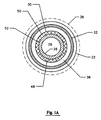
- FIG. 1A a top cross-section view of the apparatus of FIG. 1.
- the various components of the apparatus 20 have a circular cross-section.
- the ultraviolet radiation source 30 is an excimer lamp.
- the excimer ultraviolet lamp 30 may generally comprised of a cylindrical shell 48, an outer electrode 50 and an inner electrode 56.
- the gas is electrically excited by an alternating voltage which causes a current flow in the discharge gap established between the inner electrode 52 and the outer electrode 50.
- the ultraviolet radiation generated by the excimers is generally directed outward from the cylindrical shell 48.
- the excimer ultraviolet lamp 30 of the present invention operates at a significantly lower temperatures than traditional mercury based ultraviolet lamps.
- the excimer ultraviolet lamp 30 of the present invention still requires cooling to prevent overheating of the lamp 30, the fill pipe 26 and the bottle 22.
- the product flowing through the central aperture 28 of the fill pipe 26 into the bottle 22 acts to remove heat from the excimer ultraviolet lamp 30.
- the product may be maintained at a predetermined temperature which is below the operating temperature of the excimer ultraviolet lamp 30 in order for the cooling fluid to act as a heat sink to remove heat from the lamp 30 as the cooling fluid flows through the central aperture 28.
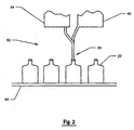
- a series of bottles 22 are conveyed along a conveyor system 60.
- the apparatus 20 connects to the bottle 22 thereby placing the fill pipe in flow communication with the interior of the bottle 22.
- the connection may be assisted by a vacuum created between the apparatus and the interior of the bottle 22, or through placement of the fill pipe 26 into the opening 24 of the bottle 22.
- Above the conveyor system 60 is a product tank 64 and a oxygen source 40. After each bottle 22 is sterilized and filled with a product, the bottle is conveyed to a sealing station further down the line.
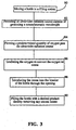
- a method of the present invention is set forth in the flow diagram of FIG. 3.
- a bottle is moved toward the filling station of a filling and sealing machine.
- the bottle has an opening thereby exposing the interior of the bottle.
- the filling station as set forth in FIG. 1, has a fill pipe 26 for delivering a desired contents to the bottle 22.
- a ultraviolet radiation source 30 Surrounding the fill pipe 26 nearest the opening of the bottle22 is a ultraviolet radiation source 30.
- a tube32 which has a diameter large enough to provide a gap 38 between the ultraviolet radiation source 30 and the inner wall 34 of the tube 32.
- an ultraviolet radiation source 30 capable of generating a substantially monochromatic radiation.
- the radiation has a wavelength less than 200 nanometers.
- a predetermined quantity of oxygen gas flows through the gap 38 and pass the ultraviolet radiation source 30.
- the oxygen is irradiated with sufficient radiation from the ultraviolet radiation source 30 to convert the oxygen from oxygen to ozone.
- the ozone is introduced to the interior of the bottle 22 thereby sterilizing the bottle 22.
- the product is dispensed through the fill pipe 26 into the bottle 22 thereby evacuating the remaining ozone from the bottle 22 as the bottle 22 is filled with the product.
- the desired product preferably may be milk, juice or water.
- other pumpable foods are within the scope of the present invention including soups, yogurts, cheeses, pastas and the like.
- the type of container, or the desired product should not be a limitation on the present invention as long as the container has an opening and the product is flowable.
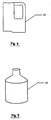
- FIG. 4 There is shown in FIG. 4 a blow moulded HDPE bottle sterilized using the present invention.
- FIG. 5 a PET bottle sterilized using the present invention.
Landscapes
- Health & Medical Sciences (AREA)
- General Health & Medical Sciences (AREA)
- Engineering & Computer Science (AREA)
- Mechanical Engineering (AREA)
- Toxicology (AREA)
- Epidemiology (AREA)
- Life Sciences & Earth Sciences (AREA)
- Animal Behavior & Ethology (AREA)
- Public Health (AREA)
- Veterinary Medicine (AREA)
- Filling Of Jars Or Cans And Processes For Cleaning And Sealing Jars (AREA)
- Apparatus For Disinfection Or Sterilisation (AREA)
Description

Claims (16)
- A method of sterilizing a container (22) undergoing aseptic filling on a filling machine, which method comprises:CHARACTERIZED IN THATmoving the container (22) to a position near a processing station (62) and a source (30) of ultraviolet radiation;feeding oxygen past the radiation source (30) to convert it to ozone;feeding the ozone so produced into the container (22) through an access opening, thereby sterilizing the container; andfilling the container with a product through a fill pipe (26),
the ultraviolet radiation source (30) is capable of generating substantially monochromatic radiation of wavelength less than 200nm, and encompasses the fill pipe (26), with a tube (32) encompassing the fill pipe and the radiation source to define a cylindrical passage (38) for the conversion of oxygen to ozone for feeding to the container (22). - A method according to Claim 1 including the step of evacuating excess ozone from the container (22) subsequent to sterilization.
- A method according to Claim 1 or Claim 2 wherein the ultraviolet radiation source (30) is an excimer ultraviolet lamp having a monochromatic wavelength.
- A method according to Claim 3 wherein the excimer ultraviolet lamp comprises a shell filled with xenon gas.
- A method according to any preceding Claim wherein the step of filling the container (22) with a product serves to cool the ultraviolet radiation source (30).
- A method according to any preceding Claim wherein the diameter of the tube (32) is less than that of the access opening into the container (22).
- A method according to any preceding Claim wherein the container is one of a PET bottle, a HDPE blow moulded bottle, a PET cup, a polyethylene bottle and a polypropylene bottle.
- Apparatus for sterilizing containers (22) undergoing aseptic filling on a filling machine, comprising a source (30) of ultraviolet radiation for converting oxygen into ozone; and means for feeding oxygen past the source (30) and into a container through an access opening to sterlilize the container,
CHARACTERIZED IN THAT
the source (30) of ultraviolet radiation is capable of generating substantially monochromatic radiation of wavelength less than 200nm, and encompasses a fill pipe (26) for filling a sterilized container (22) with product,
AND IN THAT
a tube (32) encompasses the fill pipe (26) and the radiation source (30) to define a cylindrical passage (38) for the conversion of oxygen to ozone as it is fed to a said container (22). - Apparatus according to Claim 8 for sterlizing a container having an access opening of predetermined diameter, wherein the diameter of the tube (32) is less than said predetermined diameter.
- Apparatus according to Claim 8 or Claim 9 including a container engagement device for providing a temporary seal between the tube (32) and the access opening of a said container (22) during sterilization.
- Apparatus according to Claim 10 wherein the engagement device comprises a gasket (36).
- Apparatus according to Claim 10 or Claim 11 including a gripping mechanism for urging the container opening against the tube (32) to form a tight seal therebetween.
- Apparatus according to any of Claims 8 to 12 wherein the tube (32) is composed of a stainless steel material.
- Apparatus according to any of Claims 8 to 13 wherein the ultraviolet radiation source (30) is an excimer ultraviolet lamp.
- Apparatus according to Claim 14 wherein the excimer ultraviolet lamp comprises a shell filled with xenon gas.
- A machine for aseptically sterilizing and filling containers comprising apparatus according to any of Claims 8 to 15, and means for delivering containers seriatim thereto.
Applications Claiming Priority (3)
| Application Number | Priority Date | Filing Date | Title |
|---|---|---|---|
| US911970 | 1997-08-15 | ||
| US08/911,970 US5928607A (en) | 1997-08-15 | 1997-08-15 | Bottle sterilization method and apparatus |
| PCT/US1998/015775 WO1999008933A1 (en) | 1997-08-15 | 1998-07-30 | Bottle sterilization method and apparatus |
Publications (2)
| Publication Number | Publication Date |
|---|---|
| EP1003674A1 EP1003674A1 (en) | 2000-05-31 |
| EP1003674B1 true EP1003674B1 (en) | 2004-05-06 |
Family
ID=25431193
Family Applications (1)
| Application Number | Title | Priority Date | Filing Date |
|---|---|---|---|
| EP98943174A Expired - Lifetime EP1003674B1 (en) | 1997-08-15 | 1998-07-30 | Bottle sterilization method and apparatus |
Country Status (6)
| Country | Link |
|---|---|
| US (1) | US5928607A (en) |
| EP (1) | EP1003674B1 (en) |
| JP (1) | JP3914387B2 (en) |
| AU (1) | AU9102498A (en) |
| DE (1) | DE69823669T2 (en) |
| WO (1) | WO1999008933A1 (en) |
Cited By (2)
| Publication number | Priority date | Publication date | Assignee | Title |
|---|---|---|---|---|
| CN100519400C (en) * | 2006-06-05 | 2009-07-29 | 马泽民 | Method for preventing barreled drinking water from being polluted in circulation link |
| US11147894B2 (en) | 2007-11-19 | 2021-10-19 | Sidel Participations | Device for transporting a hollow body, installation provided with such devices, and method for conveying a hollow body attached to such a device |
Families Citing this family (21)
| Publication number | Priority date | Publication date | Assignee | Title |
|---|---|---|---|---|
| DE19642987A1 (en) * | 1996-10-18 | 1998-04-23 | Tetra Laval Holdings & Finance | Method and device for sterilizing and filling packaging containers |
| AU773303B2 (en) * | 1999-09-07 | 2004-05-20 | Alcoa Deutschland Gmbh | Device and method for filling containers in a sterile manner |
| GB0025284D0 (en) * | 2000-10-14 | 2000-11-29 | Elopak Systems | Method and apparatus |
| US6747419B2 (en) * | 2002-07-03 | 2004-06-08 | Ushio America, Inc. | Method and apparatus for heat pipe cooling of an excimer lamp |
| SE525036C2 (en) * | 2003-04-04 | 2004-11-16 | Born To Run Design Hb | Device and method for sterilizing, filling and sealing a package |
| DK1598274T3 (en) * | 2004-05-21 | 2008-02-18 | Sisi Werke Gmbh | Apparatus and method for filling flexible foil bags |
| US20060032189A1 (en) * | 2004-08-13 | 2006-02-16 | Giacobbe Frederick W | Process and method of sterilizing aseptic containers |
| GB2417486B (en) * | 2004-08-24 | 2006-08-09 | Sparkling Services Ltd | Water purification apparatus |
| US7481974B2 (en) * | 2005-02-17 | 2009-01-27 | Charles Sizer | Method and apparatus for sterilizing containers |
| SE529110C2 (en) * | 2005-09-29 | 2007-05-02 | Forskarpatent I Syd Ab | Method of replacing a gaseous sterilizing agent in a package |
| DE102007017938C5 (en) * | 2007-04-13 | 2017-09-21 | Khs Gmbh | Container manufacturing apparatus and mold production method |
| EP1982920A1 (en) * | 2007-04-19 | 2008-10-22 | Krones AG | Device for sterilising containers |
| DE102008023797A1 (en) * | 2008-05-15 | 2009-11-19 | Krones Ag | Device for sterilizing container closures |
| IES20090400A2 (en) | 2009-05-22 | 2011-03-30 | Ann Marie Durkin | A sterilising apparatus |
| FR2953414B1 (en) * | 2009-12-03 | 2012-04-06 | Hema | TREATMENT DEVICE FOR STERILIZING CONTAINERS AND FILLING SAID CONTAINERS |
| FR2975086B1 (en) * | 2011-05-13 | 2013-06-28 | Valois Sas | FLUID PRODUCT DISPENSER. |
| DE102011056260A1 (en) * | 2011-12-12 | 2013-06-13 | Krones Ag | Container sterilization with UV radiation |
| DE102012108042A1 (en) * | 2012-08-30 | 2014-03-06 | Klaus Nonnenmacher | Device and method for disinfecting containers |
| KR101539756B1 (en) * | 2014-11-03 | 2015-07-28 | 성용재 | packing method of natural water and natural water using the same |
| US10596285B2 (en) * | 2016-12-29 | 2020-03-24 | Ushio Denki Kabushiki Kaisha | Sterilizing method |
| US11007292B1 (en) | 2020-05-01 | 2021-05-18 | Uv Innovators, Llc | Automatic power compensation in ultraviolet (UV) light emission device, and related methods of use, particularly suited for decontamination |
Family Cites Families (19)
| Publication number | Priority date | Publication date | Assignee | Title |
|---|---|---|---|---|
| US1984457A (en) * | 1932-06-06 | 1934-12-18 | Gen Electric Vapor Lamp Co | Apparatus for irradiating containers |
| US2597791A (en) * | 1947-10-24 | 1952-05-20 | Graham Enock Mfg Company Ltd | Machine for filling and capping bottles and like containers |
| US2546205A (en) * | 1948-06-28 | 1951-03-27 | Standard Cap & Seal Corp | Bottle capping machine |
| CA1010224A (en) * | 1973-02-12 | 1977-05-17 | Neville A. Baron | Asepticizing of contact lenses |
| SE389315B (en) * | 1974-03-18 | 1976-11-01 | Ziristor Ab | KIT AND DEVICE FOR PRE-STERILIZATION OF PACKAGING MACHINE. |
| US4121107A (en) * | 1974-04-10 | 1978-10-17 | Bbc Brown, Boveri & Company Limited | Apparatus for automatic low-bacteria to aseptic filling and packing of foodstuffs |
| US4175140A (en) * | 1974-04-10 | 1979-11-20 | Aluminiumwerke Ag. Rorschach | Method for automatic low-bacteria to aseptic filling and packing of foodstuffs employing ultraviolet radiation |
| CH578457A5 (en) * | 1974-11-08 | 1976-08-13 | Bbc Brown Boveri & Cie | |
| IN153503B (en) * | 1979-01-11 | 1984-07-21 | Nat Res Dev | |
| US4309388A (en) * | 1980-02-04 | 1982-01-05 | Tenney Robert I | Ozone sterilizing apparatus |
| CA1155271A (en) * | 1980-03-31 | 1983-10-18 | Dai Nippon Insatsu Kabushiki Kaisha | Method and apparatus for sterilizing food packages or the like |
| IT1201997B (en) * | 1985-11-11 | 1989-02-02 | Consiglio Nazionale Ricerche | PROCEDURE FOR SANITIZING CONTAINERS AND PACKAGING MATERIALS, PARTICULARLY FOR PHARMACEUTICAL AND COSMETIC USE, AND PLANT FOR PERFORMING THE PROCEDURE |
| DE3808058C2 (en) * | 1988-03-11 | 1995-05-24 | Tetra Pak Ab | Device for the sterile packaging of flowable filling goods |
| US5135714A (en) * | 1990-03-08 | 1992-08-04 | Fmc Corporation | Process for sterilizing a web of packaging material |
| US5166528A (en) * | 1991-10-04 | 1992-11-24 | Le Vay Thurston C | Microwave-actuated ultraviolet sterilizer |
| US5304352A (en) * | 1992-01-13 | 1994-04-19 | Bellettini Arturo G | Atmospheric ultra-violet laser ozonogenesis |
| US5326542A (en) * | 1992-10-01 | 1994-07-05 | Tetra Laval Holdings & Finance S.A. | Method and apparatus for sterilizing cartons |
| US5334355A (en) * | 1993-03-12 | 1994-08-02 | Cyclo3 pss Medical Systems, Inc. | Ozone sterilization system spent sterilization agent destruct and ambient air mixing device |
| DE4407183A1 (en) * | 1994-03-04 | 1995-09-07 | Bernd Uhlig | Batch UV-sterilisation enables re-use of used containers |
-
1997
- 1997-08-15 US US08/911,970 patent/US5928607A/en not_active Expired - Lifetime
-
1998
- 1998-07-30 DE DE69823669T patent/DE69823669T2/en not_active Expired - Lifetime
- 1998-07-30 WO PCT/US1998/015775 patent/WO1999008933A1/en active IP Right Grant
- 1998-07-30 AU AU91024/98A patent/AU9102498A/en not_active Abandoned
- 1998-07-30 EP EP98943174A patent/EP1003674B1/en not_active Expired - Lifetime
- 1998-07-30 JP JP2000509634A patent/JP3914387B2/en not_active Expired - Fee Related
Cited By (2)
| Publication number | Priority date | Publication date | Assignee | Title |
|---|---|---|---|---|
| CN100519400C (en) * | 2006-06-05 | 2009-07-29 | 马泽民 | Method for preventing barreled drinking water from being polluted in circulation link |
| US11147894B2 (en) | 2007-11-19 | 2021-10-19 | Sidel Participations | Device for transporting a hollow body, installation provided with such devices, and method for conveying a hollow body attached to such a device |
Also Published As
| Publication number | Publication date |
|---|---|
| EP1003674A1 (en) | 2000-05-31 |
| JP3914387B2 (en) | 2007-05-16 |
| JP2001514997A (en) | 2001-09-18 |
| WO1999008933A1 (en) | 1999-02-25 |
| DE69823669D1 (en) | 2004-06-09 |
| US5928607A (en) | 1999-07-27 |
| DE69823669T2 (en) | 2004-09-23 |
| AU9102498A (en) | 1999-03-08 |
Similar Documents
| Publication | Publication Date | Title |
|---|---|---|
| EP1003674B1 (en) | Bottle sterilization method and apparatus | |
| US5843374A (en) | Method and apparatus for sterilizing packaging | |
| US4309388A (en) | Ozone sterilizing apparatus | |
| US4175140A (en) | Method for automatic low-bacteria to aseptic filling and packing of foodstuffs employing ultraviolet radiation | |
| JP3595674B2 (en) | Sterilization of packaging with UV and hydrogen peroxide gas | |
| JP6282667B2 (en) | Apparatus and method for sterilizing a packaging container with an electron beam | |
| CA2506640C (en) | Apparatus and method for filling flexible foil bags | |
| US6037598A (en) | Arrangement on an ultraviolet sterilization system | |
| JP7409452B2 (en) | Aseptic filling machine and aseptic filling method | |
| EP1120121A3 (en) | Ultra-violet container/closure sterilisation system | |
| US5653091A (en) | Process for sterilizing and filling packages for flowable media, device for this purpose and use with a particular package | |
| WO2013137321A1 (en) | Preform sterilization method and device | |
| JP2001514997A5 (en) | ||
| EP0436042A1 (en) | Method of sterilization of container for sterile packing | |
| WO2018186484A1 (en) | Aseptic filling method and aseptic filling machine | |
| JP2002504051A (en) | Priority heating method of materials by using non-ionizing electromagnetic radiation | |
| US5809739A (en) | Filling machine having a system to aid in cleaning exterior surfaces of cartons filled thereby | |
| JP4046516B2 (en) | Air conveyor type container sterilizer | |
| JPH07147949A (en) | Aseptically packing method for stoppered bag container | |
| EP1197432A1 (en) | Method and apparatus for rendering non-viable mirco-organisms in a partially completed container | |
| JP2002205714A (en) | Sterile filling device | |
| JP3376474B2 (en) | Sterilizer | |
| WO2021162094A1 (en) | Method for measuring hydrogen peroxide content on container inner surface | |
| JP2772594B2 (en) | Sterilizer | |
| JPH1156317A (en) | Device for producing packed food, sterilization of device for producing packed food and production of packed food |
Legal Events
| Date | Code | Title | Description |
|---|---|---|---|
| PUAI | Public reference made under article 153(3) epc to a published international application that has entered the european phase |
Free format text: ORIGINAL CODE: 0009012 |
|
| 17P | Request for examination filed |
Effective date: 20000221 |
|
| AK | Designated contracting states |
Kind code of ref document: A1 Designated state(s): DE FR GB IT |
|
| 17Q | First examination report despatched |
Effective date: 20020816 |
|
| GRAP | Despatch of communication of intention to grant a patent |
Free format text: ORIGINAL CODE: EPIDOSNIGR1 |
|
| GRAS | Grant fee paid |
Free format text: ORIGINAL CODE: EPIDOSNIGR3 |
|
| GRAA | (expected) grant |
Free format text: ORIGINAL CODE: 0009210 |
|
| AK | Designated contracting states |
Kind code of ref document: B1 Designated state(s): DE FR GB IT |
|
| REG | Reference to a national code |
Ref country code: GB Ref legal event code: FG4D |
|
| REF | Corresponds to: |
Ref document number: 69823669 Country of ref document: DE Date of ref document: 20040609 Kind code of ref document: P |
|
| ET | Fr: translation filed | ||
| PLBE | No opposition filed within time limit |
Free format text: ORIGINAL CODE: 0009261 |
|
| STAA | Information on the status of an ep patent application or granted ep patent |
Free format text: STATUS: NO OPPOSITION FILED WITHIN TIME LIMIT |
|
| 26N | No opposition filed |
Effective date: 20050208 |
|
| REG | Reference to a national code |
Ref country code: FR Ref legal event code: PLFP Year of fee payment: 19 |
|
| PGFP | Annual fee paid to national office [announced via postgrant information from national office to epo] |
Ref country code: FR Payment date: 20160613 Year of fee payment: 19 |
|
| PGFP | Annual fee paid to national office [announced via postgrant information from national office to epo] |
Ref country code: GB Payment date: 20160727 Year of fee payment: 19 Ref country code: DE Payment date: 20160726 Year of fee payment: 19 Ref country code: IT Payment date: 20160720 Year of fee payment: 19 |
|
| REG | Reference to a national code |
Ref country code: DE Ref legal event code: R119 Ref document number: 69823669 Country of ref document: DE |
|
| GBPC | Gb: european patent ceased through non-payment of renewal fee |
Effective date: 20170730 |
|
| REG | Reference to a national code |
Ref country code: FR Ref legal event code: ST Effective date: 20180330 |
|
| PG25 | Lapsed in a contracting state [announced via postgrant information from national office to epo] |
Ref country code: GB Free format text: LAPSE BECAUSE OF NON-PAYMENT OF DUE FEES Effective date: 20170730 Ref country code: DE Free format text: LAPSE BECAUSE OF NON-PAYMENT OF DUE FEES Effective date: 20180201 |
|
| PG25 | Lapsed in a contracting state [announced via postgrant information from national office to epo] |
Ref country code: FR Free format text: LAPSE BECAUSE OF NON-PAYMENT OF DUE FEES Effective date: 20170731 |
|
| PG25 | Lapsed in a contracting state [announced via postgrant information from national office to epo] |
Ref country code: IT Free format text: LAPSE BECAUSE OF NON-PAYMENT OF DUE FEES Effective date: 20170730 |