EP1003041A2 - Verfahren und Vorrichtung zur berührungslosen Drehzahlmessung eines rotierenden Körpers - Google Patents
Verfahren und Vorrichtung zur berührungslosen Drehzahlmessung eines rotierenden Körpers Download PDFInfo
- Publication number
- EP1003041A2 EP1003041A2 EP99120193A EP99120193A EP1003041A2 EP 1003041 A2 EP1003041 A2 EP 1003041A2 EP 99120193 A EP99120193 A EP 99120193A EP 99120193 A EP99120193 A EP 99120193A EP 1003041 A2 EP1003041 A2 EP 1003041A2
- Authority
- EP
- European Patent Office
- Prior art keywords
- light
- rotating body
- speed
- measurement
- detected
- Prior art date
- Legal status (The legal status is an assumption and is not a legal conclusion. Google has not performed a legal analysis and makes no representation as to the accuracy of the status listed.)
- Ceased
Links
- 238000005259 measurement Methods 0.000 title claims abstract description 32
- 238000000034 method Methods 0.000 title claims abstract description 22
- 230000011664 signaling Effects 0.000 claims description 14
- 238000011156 evaluation Methods 0.000 claims description 6
- 239000004065 semiconductor Substances 0.000 claims description 4
- 238000012935 Averaging Methods 0.000 claims description 2
- 230000015572 biosynthetic process Effects 0.000 claims 1
- 238000009987 spinning Methods 0.000 description 5
- 238000011109 contamination Methods 0.000 description 3
- 238000009434 installation Methods 0.000 description 3
- 230000004446 light reflex Effects 0.000 description 3
- 230000001133 acceleration Effects 0.000 description 2
- 230000001960 triggered effect Effects 0.000 description 2
- 230000005540 biological transmission Effects 0.000 description 1
- 238000007796 conventional method Methods 0.000 description 1
- 238000013461 design Methods 0.000 description 1
- 238000001514 detection method Methods 0.000 description 1
- 239000000428 dust Substances 0.000 description 1
- 230000000694 effects Effects 0.000 description 1
- 230000002349 favourable effect Effects 0.000 description 1
- 239000000835 fiber Substances 0.000 description 1
- 238000012544 monitoring process Methods 0.000 description 1
- 238000007383 open-end spinning Methods 0.000 description 1
- 230000001105 regulatory effect Effects 0.000 description 1
- 230000002459 sustained effect Effects 0.000 description 1
Images

Classifications
-
- G—PHYSICS
- G01—MEASURING; TESTING
- G01D—MEASURING NOT SPECIALLY ADAPTED FOR A SPECIFIC VARIABLE; ARRANGEMENTS FOR MEASURING TWO OR MORE VARIABLES NOT COVERED IN A SINGLE OTHER SUBCLASS; TARIFF METERING APPARATUS; MEASURING OR TESTING NOT OTHERWISE PROVIDED FOR
- G01D5/00—Mechanical means for transferring the output of a sensing member; Means for converting the output of a sensing member to another variable where the form or nature of the sensing member does not constrain the means for converting; Transducers not specially adapted for a specific variable
- G01D5/12—Mechanical means for transferring the output of a sensing member; Means for converting the output of a sensing member to another variable where the form or nature of the sensing member does not constrain the means for converting; Transducers not specially adapted for a specific variable using electric or magnetic means
- G01D5/244—Mechanical means for transferring the output of a sensing member; Means for converting the output of a sensing member to another variable where the form or nature of the sensing member does not constrain the means for converting; Transducers not specially adapted for a specific variable using electric or magnetic means influencing characteristics of pulses or pulse trains; generating pulses or pulse trains
- G01D5/24471—Error correction
- G01D5/24476—Signal processing
-
- G—PHYSICS
- G01—MEASURING; TESTING
- G01D—MEASURING NOT SPECIALLY ADAPTED FOR A SPECIFIC VARIABLE; ARRANGEMENTS FOR MEASURING TWO OR MORE VARIABLES NOT COVERED IN A SINGLE OTHER SUBCLASS; TARIFF METERING APPARATUS; MEASURING OR TESTING NOT OTHERWISE PROVIDED FOR
- G01D5/00—Mechanical means for transferring the output of a sensing member; Means for converting the output of a sensing member to another variable where the form or nature of the sensing member does not constrain the means for converting; Transducers not specially adapted for a specific variable
- G01D5/12—Mechanical means for transferring the output of a sensing member; Means for converting the output of a sensing member to another variable where the form or nature of the sensing member does not constrain the means for converting; Transducers not specially adapted for a specific variable using electric or magnetic means
- G01D5/244—Mechanical means for transferring the output of a sensing member; Means for converting the output of a sensing member to another variable where the form or nature of the sensing member does not constrain the means for converting; Transducers not specially adapted for a specific variable using electric or magnetic means influencing characteristics of pulses or pulse trains; generating pulses or pulse trains
- G01D5/24471—Error correction
- G01D5/2448—Correction of gain, threshold, offset or phase control
-
- G—PHYSICS
- G01—MEASURING; TESTING
- G01P—MEASURING LINEAR OR ANGULAR SPEED, ACCELERATION, DECELERATION, OR SHOCK; INDICATING PRESENCE, ABSENCE, OR DIRECTION, OF MOVEMENT
- G01P3/00—Measuring linear or angular speed; Measuring differences of linear or angular speeds
- G01P3/42—Devices characterised by the use of electric or magnetic means
- G01P3/44—Devices characterised by the use of electric or magnetic means for measuring angular speed
- G01P3/48—Devices characterised by the use of electric or magnetic means for measuring angular speed by measuring frequency of generated current or voltage
- G01P3/481—Devices characterised by the use of electric or magnetic means for measuring angular speed by measuring frequency of generated current or voltage of pulse signals
-
- G—PHYSICS
- G01—MEASURING; TESTING
- G01P—MEASURING LINEAR OR ANGULAR SPEED, ACCELERATION, DECELERATION, OR SHOCK; INDICATING PRESENCE, ABSENCE, OR DIRECTION, OF MOVEMENT
- G01P3/00—Measuring linear or angular speed; Measuring differences of linear or angular speeds
- G01P3/42—Devices characterised by the use of electric or magnetic means
- G01P3/44—Devices characterised by the use of electric or magnetic means for measuring angular speed
- G01P3/48—Devices characterised by the use of electric or magnetic means for measuring angular speed by measuring frequency of generated current or voltage
- G01P3/481—Devices characterised by the use of electric or magnetic means for measuring angular speed by measuring frequency of generated current or voltage of pulse signals
- G01P3/486—Devices characterised by the use of electric or magnetic means for measuring angular speed by measuring frequency of generated current or voltage of pulse signals delivered by photo-electric detectors
Definitions
- the invention relates to a method according to the preamble of Claim 1. Furthermore, the invention relates to a device to carry out the procedure.
- the rotor washer has a light source facing outside means on which the incident light reflect from time to time or the reflection of light from time to time interrupt or change. Part of the reflected light the light source hits a measuring device and is in Signals for a speed measurement of the rotor converted.
- Diffuse sensors are known from DE 195 31 660 A1, where the presence of a spot of light in a Image plane is detected.
- To record the speed and of Changes in speed, especially during a Acceleration or deceleration phase of the rotor is that Reception system of a retro-reflective sensor on one Surface of the rotating body scattered by the lens Light beam set, and the rotating body has on the line of light beam has several weakly reflecting ones Holes.
- the surface of the support disc acts as an image plane. When the light spot dips into an opening, its image lies clearly behind it and is no longer recognized.
- the well-known Device works with threshold settings in the Way that the threshold value with the absolute value of the Brightness of the light reflected from the rotating body compared and the reflected light into binary electrical Impulses is converted. As long as the threshold is not is exceeded or is not at least reached, none Count signal triggered. A threshold exceeded in the absolute brightness of the reflected light leads to Registration of a corresponding count signal.
- the intensity of the reflected light is not required in the method according to the invention.
- the surface of the rotating body is so strong dirty that their signal or that of the Sensor device detected intensity of the surface reflected light is only slightly larger than the signal the bottom of a hole or a through hole the signal from the background is enough for a small one Difference between successively detected measurement levels in order to achieve sustained safe signaling. Becomes a certain relatively small difference value is reached a corresponding signal, such as a Counting pulse.
- working sensor device also enables one error-free signaling for difference values that are essential are lower than those of conventional ones, especially two Distances necessary for working procedures between the different brightness values.
- the measurement levels are preferably determined by averaging successively detected intensity values and especially generated if after a succession with same tendency of differing intensity values several identical intensity values or with a relatively lower value Bear deviation from each other. This will make the measurement level correctly recorded and incorrect signaling by detected and individual intensity values lying between the measurement levels avoided.
- the wavelength of the light beam is preferably in the area of the visible red light, in particular at 670 nm. Due to the light absorbing behavior of Contamination such as fiber dust, which with red light or especially with red light from a laser light beam pronounced, can also with increasing pollution of the Body sufficient for error-free signaling Difference between the measurement levels can be ensured. On additional advantage of the red light is the visibility, which allows to align the sensor during assembly no additional means such as auxiliary light sources or mechanical gauges are needed.
- the light source is preferably a semiconductor laser device educated. With the semiconductor laser device Sufficient measuring certainty required transmission light intensity can be generated in a small space.
- the preferred arrangement the sensor device and the evaluation device in one common housing enables a compact design and a easy installation.
- the inventive method for contactless Speed measurement of rotating bodies increases measurement reliability and avoids incorrect signaling.
- a light source 1 designed as a semiconductor laser device directs a laser light beam 2, as shown in FIG. 1 on a support disc 3.
- Support disc 3 carries a tread 5 on the circumference, which in known way to store the here for simplification rotor shaft shown serves.
- the support disc 3 has arranged concentrically around the axis of rotation 6, as a blind hole trained holes 7 on the rotating Support disc 3 the measuring range to which the laser light beam 2 is aligned.
- the laser light beam 2 is from the surface of the support disc 3 reflects and as Scattered light reflex beam 8 from a sensor device 9 receive.
- the line 10 is used to power the light source 1, the Sensor device 9 and an evaluation device 25. Die Evaluation device 25 evaluates the recognized Intensity differences for a signal output. Light source 1, sensor device 9 and evaluation device 25 are arranged in a common housing 24. Line 11 is used for signaling.
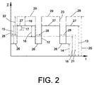
- the high measurement level 27 applied over a longer period of time is formed from the intensity values I 1H 13 generated by the reflection behavior of the smooth surface of the support disk 3, the low measurement level 26 applied only over a short period of time is obtained from the the reflection behavior of the surface of the bores 7 generated intensity values I 1D 14.
- Deviations from the average intensity value of the respective measurement level, such as can arise from fluctuations in the reflection behavior of the respective surface at a small height, are not taken into account in the illustration.
- a counting signal serving for speed measurement is generated in that after the detection of the intensity value I 1H 13, which lies above the threshold value I SW 16, the intensity value I 1D 14, which is below the threshold value I SW 16, is detected lies and thus a drop below the threshold value I SW 16 is registered.
- a counting signal serving to measure the speed is generated when, regardless of the absolute level of the respective measuring level, the difference value ⁇ I 1 15 reaches or exceeds the value I A 17.
- the value I A 17 can be chosen to be significantly smaller than that for falling below the threshold value I SW 16, starting from the level of the measurement level 27 with the intensity value I 1H 13, the minimum required difference value ⁇ I min 18 or the represented difference value ⁇ I 1 15. This increases security, for example when counting signaling for speed measurement.
- the threshold value I SW 16 must be reset or readjusted in order to get a correct speed measurement again.
- the measuring system is designed such that Counting impulses by switching to high instead of switching to be triggered at the low measuring level or if that of the Sensor device 9 received intensity value of the light under the influence of contamination of components such as Example of light source 1, which means less light is emitted, reduced.
Landscapes
- Physics & Mathematics (AREA)
- General Physics & Mathematics (AREA)
- Engineering & Computer Science (AREA)
- Signal Processing (AREA)
- Optical Transform (AREA)
- Spinning Or Twisting Of Yarns (AREA)
- Investigating Or Analysing Materials By Optical Means (AREA)
Abstract
Description
- Fig. 1
- eine Meßanordnung mit einer im Schnitt dargestellten Stützscheibe, einer Laservorrichtung sowie einer Sensoreinrichtung,
- Fig. 2
- eine schematische Darstellung der durch die gemessenen Werte der Lichtintensität gebildeten Meßpegel in Abhängigkeit von der Zeit.
Claims (8)
- Verfahren zur berührungslosen Drehzahlmessung eines rotierenden Körpers, bei dem ein von einer Lichtquelle (1) erzeugter Lichtstrahl ausgesendet und als vom rotierenden Körper reflektiertes Licht von einer Sensoreinrichtung (9) detektierbar ist, wobei die detektierten Intensitätswerte des reflektierten Lichtes durch entlang der Meßstrecke unterschiedliches Reflexionaverhalten der jeweils vom Lichtstrahl erfassten Oberfläche Signale bilden und für die Drehzahlermittlung ausgewertet werden
dadurch gekennzeichnet,
daß das Signal aus dem zwischen aufeinanderfolgend detektierten Meßpegeln (26,27;28,29) ermittelten Differenzwert (15, 22) generiert wird. - Verfahren nach Anspruch 1, dadurch gekennzeichnet, daß jeweils ein neuer Meßpegel (26,27;28,29) durch Mittelung und dann gebildet wird, wenn nach einer Aufeinanderfolge mit gleicher Tendenz voneinander abweichender Intensitätswerte mehrere gleiche Intensitätswerte oder mit relativ dazu geringer Abweichung voneinander folgen.
- Verfahren nach Anspruch 1 oder 2, dadurch gekennzeichnet, daß die Lichtquelle (1) einen Laserlichtstrahl (2) emittiert.
- Verfahren nach einem der Ansprüche 1 bis 3, dadurch gekennzeichnet, daß die Wellenlänge des Lichtstrahles im Bereich des sichtbaren Rotlichtes, insbesondere bei 670 nm, liegt.
- Verfahren nach einem der Ansprüche 1 bis 4, dadurch gekennzeichnet, daß bei Beginn der Drehbewegung des rotierenden Körpers die ersten, insbesondere die ersten drei detektierten Differenzwerte (15, 22), der Einregelung der Signalgebung dienen und nicht zur Bestimmung einer Drehzahl ausgewertet werden.
- Vorrichtung zur Ausführung des Verfahrens nach Anspruch 1, dadurch gekennzeichnet, daß die Vorrichtung Mittel zur Differenzwertbildung und davon abgeleiteten Erfassung inkrementaler Impulse sowie eine Auswerteeinrichtung (25) aufweist, die Drehzahlsignale bildet.
- Vorrichtung zur Ausführung des Verfahrens nach Anspruch 6, dadurch gekennzeichnet, daß die Lichtquelle (1) als Halbleiterlaservorrichtung ausgebildet ist.
- Vorrichtung zur Ausführung des Verfahrens nach Anspruch 6 oder 7, dadurch gekennzeichnet, daß die Sensoreinrichtung (9) und die Auswerteeinrichtung (25) in einem gemeinsamen Gehäuse (24) angeordnet sind.
Applications Claiming Priority (2)
| Application Number | Priority Date | Filing Date | Title |
|---|---|---|---|
| DE19853084 | 1998-11-18 | ||
| DE1998153084 DE19853084A1 (de) | 1998-11-18 | 1998-11-18 | Verfahren und Vorrichtung zur berührungslosen Drehzahlmessung eines rotierenden Körpers |
Publications (2)
| Publication Number | Publication Date |
|---|---|
| EP1003041A2 true EP1003041A2 (de) | 2000-05-24 |
| EP1003041A3 EP1003041A3 (de) | 2001-02-07 |
Family
ID=7888144
Family Applications (1)
| Application Number | Title | Priority Date | Filing Date |
|---|---|---|---|
| EP99120193A Ceased EP1003041A3 (de) | 1998-11-18 | 1999-10-09 | Verfahren und Vorrichtung zur berührungslosen Drehzahlmessung eines rotierenden Körpers |
Country Status (2)
| Country | Link |
|---|---|
| EP (1) | EP1003041A3 (de) |
| DE (1) | DE19853084A1 (de) |
Cited By (1)
| Publication number | Priority date | Publication date | Assignee | Title |
|---|---|---|---|---|
| EP1650572A1 (de) * | 2004-10-22 | 2006-04-26 | Getrag Ford Transmissions GmbH | Zahnrad mit Markierungen zur Geschwindigkeits- und Positionserfassung |
Families Citing this family (1)
| Publication number | Priority date | Publication date | Assignee | Title |
|---|---|---|---|---|
| DE102019004952A1 (de) | 2019-07-17 | 2021-01-21 | Truma Gerätetechnik GmbH & Co. KG | Verfahren zur Fertigung einer Heizvorrichtung sowie Heizvorrichtung |
Citations (2)
| Publication number | Priority date | Publication date | Assignee | Title |
|---|---|---|---|---|
| EP0036950A1 (de) * | 1980-03-06 | 1981-10-07 | R.J. Reynolds Tobacco Company | Dynamischer Schwellwertdetektor |
| DE4116579A1 (de) * | 1991-05-21 | 1992-11-26 | Busch Dieter & Co Prueftech | Opto-elektronische sensoranordnung sowie ein verfahren zum bestimmen von drehzahl und winkellage rotierender einrichtungen |
Family Cites Families (5)
| Publication number | Priority date | Publication date | Assignee | Title |
|---|---|---|---|---|
| US4644341A (en) * | 1984-07-05 | 1987-02-17 | Tri-Tronics Company, Inc. | Contrast indicating arrangement in photoelectric sensing systems |
| CH678457A5 (de) * | 1987-08-20 | 1991-09-13 | Landis & Gyr Betriebs Ag | |
| US4866268A (en) * | 1988-05-20 | 1989-09-12 | General Motors Corporation | Optical fast synchronization shaft position and speed sensor |
| GB2303915B (en) * | 1995-07-25 | 1997-07-23 | Gen Electric Plc | Apparatus for and a method of counting the revolutions of a rotating component |
| DE19531660A1 (de) * | 1995-08-29 | 1997-03-06 | Betr Forsch Inst Angew Forsch | Reflexions-Lichtschranke |
-
1998
- 1998-11-18 DE DE1998153084 patent/DE19853084A1/de not_active Withdrawn
-
1999
- 1999-10-09 EP EP99120193A patent/EP1003041A3/de not_active Ceased
Patent Citations (2)
| Publication number | Priority date | Publication date | Assignee | Title |
|---|---|---|---|---|
| EP0036950A1 (de) * | 1980-03-06 | 1981-10-07 | R.J. Reynolds Tobacco Company | Dynamischer Schwellwertdetektor |
| DE4116579A1 (de) * | 1991-05-21 | 1992-11-26 | Busch Dieter & Co Prueftech | Opto-elektronische sensoranordnung sowie ein verfahren zum bestimmen von drehzahl und winkellage rotierender einrichtungen |
Cited By (1)
| Publication number | Priority date | Publication date | Assignee | Title |
|---|---|---|---|---|
| EP1650572A1 (de) * | 2004-10-22 | 2006-04-26 | Getrag Ford Transmissions GmbH | Zahnrad mit Markierungen zur Geschwindigkeits- und Positionserfassung |
Also Published As
| Publication number | Publication date |
|---|---|
| EP1003041A3 (de) | 2001-02-07 |
| DE19853084A1 (de) | 2000-05-25 |
Similar Documents
| Publication | Publication Date | Title |
|---|---|---|
| EP2899565B1 (de) | Entfernungsmessender Sensor und Verfahren zur Erfassung und Abstandsbestimmung von Objekten | |
| DE4031142C3 (de) | Optischer Lichttaster und Verfahren zu seinem Betrieb | |
| EP2824478B1 (de) | Optoelektronischer Sensor und Verfahren zur Erfassung und Abstandsbestimmung von Objekten in einem Überwachungsbereich | |
| EP0066889B1 (de) | Dynamik-Steuerungsanordnung für ein Entfernungsmessgerät | |
| EP1972961B1 (de) | Optoelektronischer Sensor und Verfahren zur Messung einer Entfernung oder einer Entfernungsänderung | |
| DE4411713B4 (de) | Optische Entfernungsmeßvorrichtung und Verwendung derselben | |
| EP2045625A1 (de) | Verfahren zur Abstandsmessung und Abstandsmesseinrichtung | |
| DE102006060108A1 (de) | Laserscanner | |
| DE4312186C2 (de) | Verfahren und Vorrichtungen zur Feststellung von in einem Überwachungsbereich vorhandenen Gegenständen und/oder zur Feststellung deren Position | |
| WO2021249845A1 (de) | Verfahren und vorrichtung zu einer erkennung von verunreinigungen auf einer schutzscheibe eines lidarsensors | |
| DE19526249A1 (de) | Vorrichtung zur Erfassung von Wasser oder dergleichen auf einer Fensterscheibe eines Kraftfahrzeuges | |
| DE69019652T2 (de) | Erfassung und Messung von Signalen in faseroptischen Systemen. | |
| EP3671264B1 (de) | Sensor und verfahren zur erfassung eines objekts | |
| DE19951557B4 (de) | Optoelektronische Vorrichtung | |
| EP3839556B1 (de) | Optoelektronischer sensor und verfahren zur erfassung eines objekts | |
| DE19745493C2 (de) | Vorrichtung zur Sicherung des Rückraumbereiches eines Kraftfahrzeuges | |
| DE19522271B4 (de) | Verfahren und Vorrichtung zur Diagnose eines Dieselmotors | |
| DE19853084A1 (de) | Verfahren und Vorrichtung zur berührungslosen Drehzahlmessung eines rotierenden Körpers | |
| EP4249950A1 (de) | Erfassung und abstandsbestimmung eines objekts | |
| EP3614182B1 (de) | Lichtschrankenanordnung | |
| DE29923142U1 (de) | Empfindlichkeitsregelung für Lichttaster | |
| EP1927868A2 (de) | Opto-elektrischer Sensor | |
| EP4306998A1 (de) | Optischer sensor | |
| DE4224292C1 (de) | Verfahren zur Erkennung und Diskriminierung von Masken-, Halbmasken- und Schrägzielen unter Verwendung von optronischen Zündsensoren mit Dual-Gate-Pulslaufzeitmeßverfahren | |
| EP2179301B1 (de) | Optischer sensor |
Legal Events
| Date | Code | Title | Description |
|---|---|---|---|
| PUAI | Public reference made under article 153(3) epc to a published international application that has entered the european phase |
Free format text: ORIGINAL CODE: 0009012 |
|
| AK | Designated contracting states |
Kind code of ref document: A2 Designated state(s): BE CH DE FR LI |
|
| AX | Request for extension of the european patent |
Free format text: AL;LT;LV;MK;RO;SI |
|
| PUAL | Search report despatched |
Free format text: ORIGINAL CODE: 0009013 |
|
| AK | Designated contracting states |
Kind code of ref document: A3 Designated state(s): AT BE CH CY DE DK ES FI FR GB GR IE IT LI LU MC NL PT SE |
|
| AX | Request for extension of the european patent |
Free format text: AL;LT;LV;MK;RO;SI |
|
| 17P | Request for examination filed |
Effective date: 20010807 |
|
| AKX | Designation fees paid |
Free format text: BE CH DE FR LI |
|
| RAP1 | Party data changed (applicant data changed or rights of an application transferred) |
Owner name: SAURER GMBH & CO. KG |
|
| STAA | Information on the status of an ep patent application or granted ep patent |
Free format text: STATUS: THE APPLICATION HAS BEEN REFUSED |
|
| 18R | Application refused |
Effective date: 20060514 |