EP1002984A2 - Water hammer and noise attenuator for water pipes and taps - Google Patents
Water hammer and noise attenuator for water pipes and taps Download PDFInfo
- Publication number
- EP1002984A2 EP1002984A2 EP99122656A EP99122656A EP1002984A2 EP 1002984 A2 EP1002984 A2 EP 1002984A2 EP 99122656 A EP99122656 A EP 99122656A EP 99122656 A EP99122656 A EP 99122656A EP 1002984 A2 EP1002984 A2 EP 1002984A2
- Authority
- EP
- European Patent Office
- Prior art keywords
- housing
- damping element
- hose
- damper according
- hose section
- Prior art date
- Legal status (The legal status is an assumption and is not a legal conclusion. Google has not performed a legal analysis and makes no representation as to the accuracy of the status listed.)
- Ceased
Links
Images
Classifications
-
- F—MECHANICAL ENGINEERING; LIGHTING; HEATING; WEAPONS; BLASTING
- F16—ENGINEERING ELEMENTS AND UNITS; GENERAL MEASURES FOR PRODUCING AND MAINTAINING EFFECTIVE FUNCTIONING OF MACHINES OR INSTALLATIONS; THERMAL INSULATION IN GENERAL
- F16L—PIPES; JOINTS OR FITTINGS FOR PIPES; SUPPORTS FOR PIPES, CABLES OR PROTECTIVE TUBING; MEANS FOR THERMAL INSULATION IN GENERAL
- F16L55/00—Devices or appurtenances for use in, or in connection with, pipes or pipe systems
- F16L55/04—Devices damping pulsations or vibrations in fluids
- F16L55/045—Devices damping pulsations or vibrations in fluids specially adapted to prevent or minimise the effects of water hammer
-
- E—FIXED CONSTRUCTIONS
- E03—WATER SUPPLY; SEWERAGE
- E03C—DOMESTIC PLUMBING INSTALLATIONS FOR FRESH WATER OR WASTE WATER; SINKS
- E03C1/00—Domestic plumbing installations for fresh water or waste water; Sinks
- E03C1/02—Plumbing installations for fresh water
- E03C1/04—Water-basin installations specially adapted to wash-basins or baths
Definitions
- the invention relates to a pressure shock and noise damper for water pipes and fittings, in particular sanitary installations, according to the preamble of claim 1.
- a rubber pipe piece (2) is enclosed axially and radially as a piece of hose by means of a coaxial metal sleeve (5) as a housing, the central section of the rubber pipe piece (2) radially outwardly from an air space can form with the metal sleeve (5).
- the disadvantage of this would be that the combination of the spring characteristics of the rubber pipe piece (elastomer) or the air space (gas) are very different and do not result in a homogeneous damper unit with excellent properties.
- the invention is therefore based on the object, while eliminating the aforementioned disadvantage of the known damper, to provide a similar damper which considerably reduces both the pressure shock which arises when the water flow quickly ends and the cavitation and flow noises occurring during water flow.
- This object is achieved according to the invention by the damper according to claim 1, whose neither completely gaseous nor liquid, non-fluid damping element could consist, for example, of a granulate of elastic round grains which form small air gaps.
- Such an embodiment would also correspond to claim 2.
- a damper according to claim 3 is preferred.
- the closure bushing according to claim 4 allows the insertion of the damping element through the enlarged opening of the housing end before its insertion and the subsequent clamping of the hose piece. While primarily a flow-through damper is intended, the damper according to the invention can also represent a static cul-de-sac for the water flow, whereby both types of damper can be used together.
- the invention also relates to the uses of the invention Damper according to claim 6 or 7.
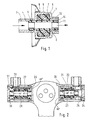
- Fig. 1 shows a longitudinal section through a housing 1, for example designed as a connecting nipple of a sanitary fitting, coaxially in the center, an elastic piece of hose 2 is inserted.
- the hose section 2 is clamped upstream in a housing bore 3 with the aid of a clamping sleeve 4 and sealing grooves 5 in the housing 1.
- a damping element 7 is installed between the outer diameter of the elastic tube piece 2 and the expanded inner diameter 6 of the housing 1.
- This damping element 7 consists of an elastomer with closed pores or of a granulate.
- the entire cavity of the enlarged central section of the housing 1 is filled with the elastomer.
- the elastomer is supported on the outside on the inside diameter 6 and laterally on two radial end faces 8 and 9 of the housing.
- a socket 10 is inserted tightly and firmly in the housing 1 downstream.
- This bushing 10 is only used after the damping element 7 is mounted.
- the end of the hose section 2 is clamped on the downstream side with the aid of a clamping sleeve 11 and sealing grooves 12, which are located in the bore of the bush 10. If a pressure shock occurs in the line, for example as a result of a valve being closed quickly, the elastic hose section 2 widens somewhat and the pressure shock is absorbed.
- the extent of the widening depends on the spring characteristic of the combination damping element 7 / elastic hose section 2 and, of course, on the amount of the pressure shock.
- the spring characteristic can be influenced by the elasticity of the hose section 2 and the elasticity of the damping element 7.
- the latter is determined by the volume of the damping element 7, by the inherent elasticity of the elastomer and by the number and size of the pores enclosed in the elastomer.
- Fig. 2 shows on the right a longitudinal partial section through a sanitary fitting 20.
- the housing 21 are, similar to Fig. 1, a elastic piece of hose 22 and a damping element 23 built-in.
- the housing 21 is fixed with a cover 24 connected and it has some slots 25, through which the inflowing water radially into the center and flows through the hose section 22 to the mixer.
- the mode of action of the damping element 23 is the same as that in FIG. 1.
- the installation of the damping element in the valve has the Advantage that standard connecting parts as connecting nipples can be used.
- FIG. 2 shows a partial longitudinal section on the left through another sanitary fitting 26.
- An elastic hose piece 28 and a damping element 29 are in turn installed in the housing 27.
- the closure cover 30 is firmly connected to the housing 27 and fastened with a thread 31 in the sanitary fitting 26.
- the inflowing water is not passed through the central bore of the hose section 28.
- the inner wall of the same is impacted by pressure surges (in the case of quick closing of fittings) and by high-frequency vibrations (in the case of cavitation noises).
- the sanitary fittings 20 and 26 each have two clamping sleeves 4 'and 11' and a locking bush 10 '.
- the sleeve 11 ' forms radially on the inside, the adjacent end of the tube piece 22 in the center and the bushing 10' radially on the outside in a coaxial arrangement.
Abstract
Description
Die Erfindung betrifft einen Druckschlag- und Geräusch-dämpfer
für Wasserleitungen und -armaturen insbesondere
sanitärer Installationen, gemäß Oberbegriff des Anspruches
1.
Bei einem derartigen, aus der DE-PS 689.184 bekannten
"geräuschdämpfenden Rohrzwischenstück" ist ein Gummirohrstück
(2) als Schlauchstück mittels einer koaxialen Metallhülse
(5) als Gehäuse axial und radial eingefasst, wobei
der mittlere Abschnitt des Gummirohrstückes (2) radial
außen einen Luftraum mit der Metallhülse (5) bilden kann.The invention relates to a pressure shock and noise damper for water pipes and fittings, in particular sanitary installations, according to the preamble of claim 1.
In such a "noise-damping pipe intermediate piece" known from DE-PS 689.184, a rubber pipe piece (2) is enclosed axially and radially as a piece of hose by means of a coaxial metal sleeve (5) as a housing, the central section of the rubber pipe piece (2) radially outwardly from an air space can form with the metal sleeve (5).
Nachteilig wäre hieran, daß die Kombination der Federkennlinien
des Gummirohrstückes (Elastomer) bzw. des Luftraumes
(Gas) stark verschieden sind und keine homogene
Dämpfereinheit mit hervorragenden Eigenschaften entstehen
lassen.
Der Erfindung liegt daher die Aufgabe zugrunde, unter Beseitigung
des zuvor genannten Nachteils des bekannten
Dämpfers einen gleichartigen Dämpfer zu schaffen, welcher
sowohl den beim schnellen Beenden des Wasserdurchflusses
entstehenden Druckschlag als auch die beim Wasserfluss auftretenden
Kavitations- und Fließgeräusche erheblich vermindert.
Diese Aufgabe ist erfindungsgemäß durch den Dämpfer gemäß
Anspruch 1 gelöst, dessen weder ganz gasförmiges noch flüssiges,
afluides Dämpfungselement z.B. aus einem Granulat elastischer
Rundkörner bestehen könnte, die kleine Luftzwischenräume
bilden. Auch eine solche Ausführung entspräche Anspruch
2. - Bevorzugt wird aber ein Dämpfer gemäß Anspruch
3.
Die Verschlußbuchse gemäß Anspruch 4 erlaubt vor ihrer Einfügung
und der anschließenden Festklemmung des Schlauchstückes
das Einbringen des Dämpfungselementes durch die
erweiterte öffnung des Gehäuseendes.
Während in erster Linie an einen durchflossenen Dämpfer
gedacht ist, kann der erfindungsgemäße Dämpfer aber auch
gemäß Anspruch 5 eine statische Sackgasse für die Wasserströmung
darstellen, wobei beide Dämpferarten gemeinsam
zum Einsatz kommen können.The disadvantage of this would be that the combination of the spring characteristics of the rubber pipe piece (elastomer) or the air space (gas) are very different and do not result in a homogeneous damper unit with excellent properties.
The invention is therefore based on the object, while eliminating the aforementioned disadvantage of the known damper, to provide a similar damper which considerably reduces both the pressure shock which arises when the water flow quickly ends and the cavitation and flow noises occurring during water flow.
This object is achieved according to the invention by the damper according to claim 1, whose neither completely gaseous nor liquid, non-fluid damping element could consist, for example, of a granulate of elastic round grains which form small air gaps. Such an embodiment would also correspond to
The closure bushing according to claim 4 allows the insertion of the damping element through the enlarged opening of the housing end before its insertion and the subsequent clamping of the hose piece.
While primarily a flow-through damper is intended, the damper according to the invention can also represent a static cul-de-sac for the water flow, whereby both types of damper can be used together.
Gegenstand der Erfindung sind auch die Verwendungen erfindungsgemäßer
Dämpfer gemäß Anspruch 6 bzw. 7. The invention also relates to the uses of the invention
Damper according to
Im Folgenden ist die Erfindung anhand dreier durch die anliegende
Zeichnung beispielhaft dargestellter Ausführungsformen
des erfindungsgemäßen Dämpfers im Einzelnen erläutert.
Es zeigt:
- Fig. 1
- einen Längsschnitt durch eine erste Ausführungsform in Verbindung mit einer Wasserleitung
- Fig. 2
- rechts und links je einen Längsschnitt durch eine zweite bzw. dritte Ausführungsform in Verbindung mit einer Wasserarmatur
It shows:
- Fig. 1
- a longitudinal section through a first embodiment in connection with a water pipe
- Fig. 2
- right and left each a longitudinal section through a second or third embodiment in connection with a water fitting
Fig. 1 zeigt einen Längsschnitt durch ein z.B. als Anschlußnippel
einer Sanitärarmatur ausgebildetes, mittig
erweitertes Gehäuse 1. Koaxial im Zentrum ist ein elastisches
Schlauchstück 2 eingesetzt. Das Schlauchstück 2 ist
stromaufwärts in einer Gehäuse-Bohrung 3 mit Hilfe einer
Klemmhülse 4 und Dichtrillen 5 im Gehäuse 1 festgeklemmt.
Zwischen dem Außendurchmesser des elastischen Schlauchstückes
2 und dem erweiterten Innendurchmesser 6 des Gehäuses
1 ist ein Dämpfungselement 7 eingebaut. Dieses Dämpfungselement
7 besteht aus einem Elastomer mit geschlossenen
Poren oder aus einem Granulat. Der ganze Hohlraum
des erweiterten Mittelabschnittes des Gehäuses 1 ist mit
dem Elastomer ausgefüllt. Das Elastomer stützt sich außen
am Innendurchmesser 6 und seitlich an zwei radialen Stirnflächen
8 und 9 des Gehäuses ab. Stromabwärts ist im Gehäuse
1 eine Buchse 10 dicht und fest eingesetzt. Diese
Buchse 10 wird erst eingesetzt, nachdem das Dämpfungselement
7 montiert ist. Am Schluß der Montage wird das Ende
des Schlauchstückes 2 auf der Seite stromabwärts mit Hilfe
einer Klemmhülse 11 und Dichtrillen 12, die sich in der
Bohrung der Buchse 10 befinden, festgeklemmt.
Tritt ein Druckschlag in der Leitung auf, z.B. infolge
schnellen Schließens einer Armatur, dann weitet sich das
elastische Schlauchstück 2 etwas auf und der Druckschlag
wird absorbiert. Das Maß der Aufweitung ist abhängig von
der Federkennlinie der Kombination Dämpfungselement 7/
elastisches Schlauchstück 2 und natürlich von der Höhe des
Druckschlages.
Die Federkennlinie kann beeinflußt werden durch die Elastizität
des Schlauchstückes 2 und die Elastizität des Dämpfungselementes
7. Letztere wird bestimmt durch das Volumen
des Dämpfungselementes 7, durch die Eigen-Elastizität des
Elastomers und durch die Anzahl und Größe der im Elastomer
eingeschlossenen Poren.
Durch richtige Kombination aller obigen Werte können optimale
Druckschlag-Dämpfungen erreicht werden.
Messungen haben gezeigt, daß die beim raschen Schließen
von Armaturen üblichen Druckschlagspitzen von gegen 30 bar
mittels des Dämpfungselementes 7 bis auf unter 10 bar reduziert
werden können.
Bei richtiger Kombination obiger Parameter werden aber auch
übliche Kavitationsgeräusche und Fließgeräusche erheblich
reduziert.Fig. 1 shows a longitudinal section through a housing 1, for example designed as a connecting nipple of a sanitary fitting, coaxially in the center, an elastic piece of
If a pressure shock occurs in the line, for example as a result of a valve being closed quickly, the
The spring characteristic can be influenced by the elasticity of the
By correctly combining all of the above values, optimal pressure shock damping can be achieved.
Measurements have shown that the pressure shock peaks which are customary when valves are closed quickly can be reduced from around 30 bar to below 10 bar by means of the
With the correct combination of the above parameters, normal cavitation noises and flow noises are also considerably reduced.
Fig. 2 zeigt rechts einen Längs-Teilschnitt durch eine Sanitärarmatur
20. Im Gehäuse 21 sind, ähnlich wie in Fig. 1, ein
elastisches Schlauchstück 22 und ein Dämpfungselement 23
eingebaut. Das Gehäuse 21 ist fest mit einem Verschlußdeckel
24 verbunden und es weist einige Schlitze 25 auf,
durch die das zufließende Wasser radial ins Zentrum und
durch das Schlauchstück 22 zum Mischer fließt. Die Wirkungsweise
des Dämpfungselementes 23 ist gleich der bei Fig. 1.
Der Einbau des Dämpfungselementes in die Armatur hat den
Vorteil, daß als Anschlußnippel übliche Standard-Teile
verwendet werden können.Fig. 2 shows on the right a longitudinal partial section through a
Fig. 2 zeigt links einen Längs-Teilschnitt durch eine andere
Sanitärarmatur 26. Im Gehäuse 27 sind wiederum ein elastisches
Schlauchstück 28 und ein Dämpfungselement 29 eingebaut.
Der Verschlußdeckel 30 ist fest mit dem Gehäuse 27
verbunden und mit einem Gewinde 31 in der Sanitärarmatur
26 befestigt.
In diesem Fall wird das zufließende Wasser nicht durch die
zentrale Bohrung des Schlauchstückes 28 geleitet. Die innere
Wandung desselben wird jedoch durch Druckschläge
(im Falle von schnellem Schließen von Armaturen) und durch
hochfrequente Schwingungen (im Falle von Kavitationsgeräuschen)
beaufschlagt.FIG. 2 shows a partial longitudinal section on the left through another
In this case, the inflowing water is not passed through the central bore of the
Die Sanitärarmaturen 20 und 26 weisen wie der Anschlussnippel
gemäß Figur 1 je zwei Klemm-Hülsen 4' und 11' sowie
eine Verschluss-Buchse 10' auf.
Bei der Armatur 20 bilden die Hülse 11' radial innen, das
benachbarte Ende des Schlauchstückes 22 mittig und die
Buchse 10' radial außen eine koaxiale Anordnung. Gleiches
gilt für die Hülse 4', die Buchse 10' und das von beiden
eingeklemmte Ende des Schlauchstückes 28.Like the connecting nipple according to FIG. 1, the
In the case of the
Claims (7)
Applications Claiming Priority (2)
| Application Number | Priority Date | Filing Date | Title |
|---|---|---|---|
| DE19853768 | 1998-11-21 | ||
| DE19853768 | 1998-11-21 |
Publications (2)
| Publication Number | Publication Date |
|---|---|
| EP1002984A2 true EP1002984A2 (en) | 2000-05-24 |
| EP1002984A3 EP1002984A3 (en) | 2000-12-13 |
Family
ID=7888565
Family Applications (1)
| Application Number | Title | Priority Date | Filing Date |
|---|---|---|---|
| EP99122656A Ceased EP1002984A3 (en) | 1998-11-21 | 1999-11-15 | Water hammer and noise attenuator for water pipes and taps |
Country Status (1)
| Country | Link |
|---|---|
| EP (1) | EP1002984A3 (en) |
Cited By (9)
| Publication number | Priority date | Publication date | Assignee | Title |
|---|---|---|---|---|
| WO2002042677A1 (en) * | 2000-11-24 | 2002-05-30 | Suzuki Sogyo Co., Ltd. | Serially connected fluid hammer preventer |
| EP1396673A1 (en) | 2002-09-09 | 2004-03-10 | Frey, Conrad | Water hammer attenuator for water pipes, especially for sanitary appliances |
| EP1640513A1 (en) * | 2004-09-28 | 2006-03-29 | Righi S.p.A. | Connection device for hydraulic circuits |
| DE102006016938B3 (en) * | 2006-04-11 | 2007-12-06 | Dr.Ing.H.C. F. Porsche Ag | Hydraulic pulsation absorber for chassis/landing gear control systems has a casing with inlet and outlet points integrated in the base of the casing |
| WO2011117128A1 (en) * | 2010-03-23 | 2011-09-29 | Continental Teves Ag & Co. Ohg | Pulsation dampening capsule |
| EP2527705A1 (en) * | 2011-05-27 | 2012-11-28 | MAHLE International GmbH | Pressure vibration damper |
| CN107191732A (en) * | 2017-07-11 | 2017-09-22 | 新疆水利水电科学研究院 | Buffer unit and buffer system |
| EP3964652A1 (en) * | 2020-09-02 | 2022-03-09 | Fujian Xihe Sanitary Ware Technology Co., Ltd. | Faucet |
| US20220196197A1 (en) * | 2019-04-23 | 2022-06-23 | Georgia Tech Research Corporation | Systems and methods for a fluid noise suppressor |
Citations (1)
| Publication number | Priority date | Publication date | Assignee | Title |
|---|---|---|---|---|
| DE689184C (en) | 1936-01-31 | 1940-03-13 | Continental Gummi Werke Akt Ge | Noise-dampening pipe adapter |
Family Cites Families (4)
| Publication number | Priority date | Publication date | Assignee | Title |
|---|---|---|---|---|
| US3665967A (en) * | 1970-01-16 | 1972-05-30 | Western Co Of North America | Supercharge hose |
| US4314621A (en) * | 1979-03-07 | 1982-02-09 | Caterpillar Tractor Co. | Fluidborne noise attenuator |
| DE3625005A1 (en) * | 1986-07-24 | 1988-01-28 | Ideal Standard | Sanitary inlet fitting for bath tubs, wash-stands or the like |
| JPH03157598A (en) * | 1989-11-15 | 1991-07-05 | Kitazawa Valve:Kk | Water hammer preventer |
-
1999
- 1999-11-15 EP EP99122656A patent/EP1002984A3/en not_active Ceased
Patent Citations (1)
| Publication number | Priority date | Publication date | Assignee | Title |
|---|---|---|---|---|
| DE689184C (en) | 1936-01-31 | 1940-03-13 | Continental Gummi Werke Akt Ge | Noise-dampening pipe adapter |
Cited By (16)
| Publication number | Priority date | Publication date | Assignee | Title |
|---|---|---|---|---|
| WO2002042677A1 (en) * | 2000-11-24 | 2002-05-30 | Suzuki Sogyo Co., Ltd. | Serially connected fluid hammer preventer |
| US6672337B2 (en) | 2000-11-24 | 2004-01-06 | Suzuki Sogyo Co., Ltd. | Serially connected fluid hammer preventer |
| KR100758050B1 (en) | 2000-11-24 | 2007-09-11 | 스즈키소교 가부시키가이샤 | Serially connected fluid hammer preventer |
| EP1396673A1 (en) | 2002-09-09 | 2004-03-10 | Frey, Conrad | Water hammer attenuator for water pipes, especially for sanitary appliances |
| WO2004025166A1 (en) | 2002-09-09 | 2004-03-25 | Frey, Conrad | Pressure damper and silencer, in particular for connections of sanitary fittings |
| US7497233B2 (en) * | 2002-09-09 | 2009-03-03 | Conrad Frey | Pressure damper and silencer, in particular for connections of sanitary fittings |
| EP1640513A1 (en) * | 2004-09-28 | 2006-03-29 | Righi S.p.A. | Connection device for hydraulic circuits |
| DE102006016938B3 (en) * | 2006-04-11 | 2007-12-06 | Dr.Ing.H.C. F. Porsche Ag | Hydraulic pulsation absorber for chassis/landing gear control systems has a casing with inlet and outlet points integrated in the base of the casing |
| WO2011117128A1 (en) * | 2010-03-23 | 2011-09-29 | Continental Teves Ag & Co. Ohg | Pulsation dampening capsule |
| CN102803034A (en) * | 2010-03-23 | 2012-11-28 | 大陆-特韦斯贸易合伙股份公司及两合公司 | Pulsation dampening capsule |
| CN102803034B (en) * | 2010-03-23 | 2015-08-05 | 大陆-特韦斯贸易合伙股份公司及两合公司 | pulsation damping cover |
| US9205820B2 (en) | 2010-03-23 | 2015-12-08 | Continental Teves Ag & Co. Ohg | Pulsation dampening capsule |
| EP2527705A1 (en) * | 2011-05-27 | 2012-11-28 | MAHLE International GmbH | Pressure vibration damper |
| CN107191732A (en) * | 2017-07-11 | 2017-09-22 | 新疆水利水电科学研究院 | Buffer unit and buffer system |
| US20220196197A1 (en) * | 2019-04-23 | 2022-06-23 | Georgia Tech Research Corporation | Systems and methods for a fluid noise suppressor |
| EP3964652A1 (en) * | 2020-09-02 | 2022-03-09 | Fujian Xihe Sanitary Ware Technology Co., Ltd. | Faucet |
Also Published As
| Publication number | Publication date |
|---|---|
| EP1002984A3 (en) | 2000-12-13 |
Similar Documents
| Publication | Publication Date | Title |
|---|---|---|
| EP3245435B1 (en) | Damping device | |
| DE102009052674B4 (en) | Method and device for connecting double-walled pipes | |
| DE4002057A1 (en) | Plug-in fitment for detachable connecting pipes - consists of housing section with inner cone, collect and seal, with sealing lips and dirt seal | |
| DE10048502C1 (en) | Plug connection with spill lock | |
| EP1002984A2 (en) | Water hammer and noise attenuator for water pipes and taps | |
| DE2657504B2 (en) | Noise damping insert for sanitary fittings | |
| EP2118541A1 (en) | Gas flow monitor | |
| DE10349925A1 (en) | Built-in valve for a radiator, in particular sectional radiator | |
| DE10163931A1 (en) | Pipe coupling has coupling block formed by connector encompassed by O-ring, and socket to receive connector, with the O-ring bearing against conical edge face of connector socket | |
| DE102007000143B4 (en) | Acetylene pressure gauge with protective choke | |
| EP1396673B1 (en) | Water hammer attenuator for water pipes, especially for sanitary appliances | |
| DE202011004778U1 (en) | Coupling part of a pressure medium line coupling | |
| DE2330552A1 (en) | PIPE OR HOSE COUPLING | |
| EP1788295B1 (en) | Connection fitting for connecting a testing device to a hose fitting of a flexible conduit | |
| DE3343131C2 (en) | Deformable pipe connection | |
| DE10201626A1 (en) | check valve | |
| EP1002983B1 (en) | Water hammer and noise attenuator for water pipes and taps | |
| DE102018102020A1 (en) | pipe fitting | |
| EP3418436A1 (en) | Hose device and assembly | |
| DE2547829A1 (en) | Manometer shock absorbing and damping mechanism - has gas sealed chamber and sintered metal support pad with separating wall | |
| DE102010030661B4 (en) | joint assembly | |
| DE3034109A1 (en) | Sound absorber insert for sanitary fittings - consists of two sections of different characteristic vibration frequencies | |
| DE10064976A1 (en) | Valve unit with connection adapter has casing itself in form of functional blocking valve | |
| DE102007017283B4 (en) | Device for blocking a fluid passage through a tubular part by means of a check valve, in particular in a domestic appliance | |
| DE102007044543A1 (en) | Damper in pneumatic pressure system damps noise caused by pressure discharge flows from pressure side to atmosphere side |
Legal Events
| Date | Code | Title | Description |
|---|---|---|---|
| PUAI | Public reference made under article 153(3) epc to a published international application that has entered the european phase |
Free format text: ORIGINAL CODE: 0009012 |
|
| AK | Designated contracting states |
Kind code of ref document: A2 Designated state(s): AT BE CH CY DE DK ES FI FR GB GR IE IT LI LU MC NL PT SE |
|
| AX | Request for extension of the european patent |
Free format text: AL;LT;LV;MK;RO;SI |
|
| PUAL | Search report despatched |
Free format text: ORIGINAL CODE: 0009013 |
|
| AK | Designated contracting states |
Kind code of ref document: A3 Designated state(s): AT BE CH CY DE DK ES FI FR GB GR IE IT LI LU MC NL PT SE |
|
| AX | Request for extension of the european patent |
Free format text: AL;LT;LV;MK;RO;SI |
|
| 17P | Request for examination filed |
Effective date: 20010606 |
|
| AKX | Designation fees paid |
Free format text: AT BE CH CY DE DK ES FI FR GB GR IE IT LI LU MC NL PT SE |
|
| 17Q | First examination report despatched |
Effective date: 20011018 |
|
| STAA | Information on the status of an ep patent application or granted ep patent |
Free format text: STATUS: THE APPLICATION HAS BEEN REFUSED |
|
| 18R | Application refused |
Effective date: 20021129 |