EP1002256B1 - Vorrichtung zur optischen signalübertragung zwischen zwei dynamisch entkoppelten systemen - Google Patents
Vorrichtung zur optischen signalübertragung zwischen zwei dynamisch entkoppelten systemen Download PDFInfo
- Publication number
- EP1002256B1 EP1002256B1 EP98925447A EP98925447A EP1002256B1 EP 1002256 B1 EP1002256 B1 EP 1002256B1 EP 98925447 A EP98925447 A EP 98925447A EP 98925447 A EP98925447 A EP 98925447A EP 1002256 B1 EP1002256 B1 EP 1002256B1
- Authority
- EP
- European Patent Office
- Prior art keywords
- light
- light source
- fibre
- optical
- wave guide
- Prior art date
- Legal status (The legal status is an assumption and is not a legal conclusion. Google has not performed a legal analysis and makes no representation as to the accuracy of the status listed.)
- Expired - Lifetime
Links
- 230000003287 optical effect Effects 0.000 title claims description 31
- 239000000463 material Substances 0.000 claims description 26
- 238000010168 coupling process Methods 0.000 claims description 25
- 238000005859 coupling reaction Methods 0.000 claims description 24
- 230000008878 coupling Effects 0.000 claims description 22
- 230000001427 coherent effect Effects 0.000 claims description 12
- 230000008054 signal transmission Effects 0.000 claims description 11
- 230000035515 penetration Effects 0.000 claims 1
- 239000013307 optical fiber Substances 0.000 description 78
- 239000000835 fiber Substances 0.000 description 8
- 230000000694 effects Effects 0.000 description 5
- 230000005855 radiation Effects 0.000 description 4
- 230000005540 biological transmission Effects 0.000 description 3
- 230000005684 electric field Effects 0.000 description 2
- 238000005286 illumination Methods 0.000 description 2
- 230000000284 resting effect Effects 0.000 description 2
- 238000006243 chemical reaction Methods 0.000 description 1
- 230000002996 emotional effect Effects 0.000 description 1
- 239000003365 glass fiber Substances 0.000 description 1
- 230000001771 impaired effect Effects 0.000 description 1
- 230000001678 irradiating effect Effects 0.000 description 1
- 239000007788 liquid Substances 0.000 description 1
- 239000004973 liquid crystal related substance Substances 0.000 description 1
- 238000004519 manufacturing process Methods 0.000 description 1
- 230000000737 periodic effect Effects 0.000 description 1
- 230000000638 stimulation Effects 0.000 description 1
- 239000000126 substance Substances 0.000 description 1
Images
Classifications
-
- G—PHYSICS
- G02—OPTICS
- G02F—OPTICAL DEVICES OR ARRANGEMENTS FOR THE CONTROL OF LIGHT BY MODIFICATION OF THE OPTICAL PROPERTIES OF THE MEDIA OF THE ELEMENTS INVOLVED THEREIN; NON-LINEAR OPTICS; FREQUENCY-CHANGING OF LIGHT; OPTICAL LOGIC ELEMENTS; OPTICAL ANALOGUE/DIGITAL CONVERTERS
- G02F1/00—Devices or arrangements for the control of the intensity, colour, phase, polarisation or direction of light arriving from an independent light source, e.g. switching, gating or modulating; Non-linear optics
- G02F1/01—Devices or arrangements for the control of the intensity, colour, phase, polarisation or direction of light arriving from an independent light source, e.g. switching, gating or modulating; Non-linear optics for the control of the intensity, phase, polarisation or colour
- G02F1/011—Devices or arrangements for the control of the intensity, colour, phase, polarisation or direction of light arriving from an independent light source, e.g. switching, gating or modulating; Non-linear optics for the control of the intensity, phase, polarisation or colour in optical waveguides, not otherwise provided for in this subclass
-
- G—PHYSICS
- G02—OPTICS
- G02F—OPTICAL DEVICES OR ARRANGEMENTS FOR THE CONTROL OF LIGHT BY MODIFICATION OF THE OPTICAL PROPERTIES OF THE MEDIA OF THE ELEMENTS INVOLVED THEREIN; NON-LINEAR OPTICS; FREQUENCY-CHANGING OF LIGHT; OPTICAL LOGIC ELEMENTS; OPTICAL ANALOGUE/DIGITAL CONVERTERS
- G02F2201/00—Constructional arrangements not provided for in groups G02F1/00 - G02F7/00
- G02F2201/30—Constructional arrangements not provided for in groups G02F1/00 - G02F7/00 grating
- G02F2201/302—Constructional arrangements not provided for in groups G02F1/00 - G02F7/00 grating grating coupler
Definitions
- the invention relates to a device for optical signal transmission between two dynamically decoupled systems, with at least one, a first Transmitting device having light source, which is attached to the first system and a receiving device having at least one optical waveguide, which is attached to the second system and into which the light from the light source can be coupled.
- the waveguide designed as an optical fiber is perpendicular to Optical fiber surface irradiated, so that the light coupled into the waveguide is also oriented perpendicular to the optical fiber longitudinal axis.
- Detector arrangements are arranged at the fiber ends, carry only those parts of the light coupled into the optical fiber for signal transmission, which can be found in Can spread the direction of the optical fiber longitudinal axis and by total reflection get to the detector arrangement relatively loss-free. That share is generally negligible in the case of the side radiation described. It Measures must therefore be taken to maximize the share of the to redirect the optical fiber coupled in the direction of the longitudinal axis of the fiber, as if the light was coupled in on one end side of the optical fiber become.
- an X-ray vision device emerges that one provides ring-shaped optical waveguide, along the outer contour of a light source is moved as a signal source.
- Coupled radiation in the longitudinal direction of the optical waveguide are on the inside of the optical fiber provided steps that extend over the entire Extend circumference of the optical waveguide and cause a light reflection, so that the light of the light source coupled into the optical waveguide over the entire The extent of the optical fiber is evenly distributed.
- At least one end of the optical waveguide is a corresponding receiving unit for detecting the light intended.
- the stepped design of the inside is capable of the optical waveguide that is vertically coupled into the optical waveguide Deflect light in the longitudinal direction of the fiber, but this structure affects the propagation behavior of the light along the waveguide axis considerably, which makes light guided within the waveguide by refraction and reflection at the Step contours are partially extracted from the waveguide and thereby strong Is subject to losses.
- the coupling prism must be carried simultaneously to the light transmitter via the optical fiber, towards it is that the distance - these are orders of magnitude that are in the ⁇ m range - to be observed very precisely between the coupling prism and optical fiber is and therefore requires precision mechanics that are constructive and in particular is financially unattractive for operational use.
- the invention has for its object a device for optical Signal transmission between two dynamically decoupled systems, preferably two systems moving relative to each other, with at least one, a first Transmitting device having light source, which is attached to the first system is, and a, at least one optical fiber receiving device, the is mounted on the second system, and along its extension the light source is moved and into which the light of the light source can be coupled, to further develop that the light coupling of the originating from the transmitter Light in the optical fiber occurs as possible without large losses.
- the measures to be carried out for this purpose should also be inexpensive in production and unproblematic in use, so that the device can be used operationally at any location.
- a device formed that at least on that directly opposite the first light source A photorefractive layer is applied to the surface of the optical fiber and that at least one coherent light source is provided on the first system is, whose light is an optical one by beam superimposition at the point of light coupling Dynamically impresses the grating in the photorefractive layer via diffraction properties for the light of the first light source, so that the light in the Optical fiber can be coupled.
- the idea according to the invention takes on the property of photorefractive materials who have nonlinear optical capabilities in such a way that you Refractive index can be changed by light irradiation.
- an interference pattern by deliberately superimposing two coherent light beams to generate and image on a photorefractive material layer, so that for example a sinusoidal light intensity distribution on the surface of the photorefractive material layer results.
- the charges and contained in the photorefractive material layer move generate an electric field, the strength of which also changes sinusoidally.
- This field distorts the material layer in the same periodic manner and causes changes in the refractive index.
- a so-called Refractive index grating or refractive index volume hologram deeper This is explained in the contribution by D. M. Pepper "The photorefractive Effect ", Spektrum dermaschine, December 1990, pp. 72 - 79.
- the main idea underlying the invention relates to the generation of a local coupling point lying on the surface of the optical fiber for that from the transmitting device light directed onto the optical fiber.
- the coupling point on the Optical fiber is spatially limited, so that the remaining part of the optical fiber Leaves the light inside the optical fiber unaffected.
- This coupling point is generated in such a way that, on the one hand, the optical fiber is preferably completely covered with a photorefractive material layer, whose refractive index in the unexposed state is identical or similar to that Is the refractive index of the optical fiber. Furthermore, the one carrying the transmitting device System arranged a coherent light source, which is responsible for the generation of a Interference pattern on the surface of the photorefractive material layer on site the coupling point is provided.
- the beam of the light source can be split using a beam splitter and be superimposed on a corresponding mirror arrangement.
- two or more separate coherent light sources can also be used
- System of the transmitter can be provided, the individual light beams in one be appropriately superimposed.
- An alternative embodiment according to the invention also provides with the aid of a not necessarily coherent light source that is fixed to the system of the transmitter is coupled, by irradiating a mask, a light pattern on the To produce photorefractive layer of the light guide arrangement through which the refractive index within the photorefractive material layer periodically in the manner of a for the light of the light source of the transmitting device effective optical grating changed becomes.
- the optical phase grating that forms dynamically at the coupling point enables the light to be coupled into the optical fiber due to diffraction Direction of propagation within the optical fiber to take in the Optical fiber guided modes leads. Since the coupling grid is only at the location of the current one Coupling point through targeted radiation, can already in the Optical fibers coupled in through the rest of the optical fiber Total reflection can be continued undisturbed.
- the optical phase grating moves dynamically along the extent the optical fiber simultaneously with the transmitter.
- it is appropriate well-known effect of two-beam interference on photorefractive materials in particular for the optical signal transmission between two relative to each other moving systems, as is the case with fiber optic slip rings Case is.
- Another embodiment of the invention for coupling light into a Optical fiber using the photorefractive effect sees an optical fiber before, on the surface of a physically trained lattice structure incorporated is, preferably mechanically introduced into the contour of the optical fiber Depressions and elevations, which in themselves are a diffraction grating for the represents the optical fiber to be coupled in.
- a photorefractive material layer becomes flush with the surface of the optical fiber incorporated structure and with a smooth opposite the structure Material layer surface applied.
- the photorefractive material layer is only optical to see transparent, the optical fiber enveloping layer, through its immediate Adjacent to the structured surface of the optical fiber this is not an optical one Effect shows, especially since the refractive index of the photorefractive material layer is identical to the refractive index of the optical fiber.
- phase grating used in the above embodiment is physical is firmly provided on the surface of the optical fiber and the photorefractive Layer by refractive index to the temporary only by uniform lighting optical effectiveness of the phase grating for the input Light
- alternative materials can also be used through-external Energy input change their refractive index.
- electrically sensitive materials caused by applying an external voltage change their refractive index.
- electrodes are coated around the Arrange fiber optics that depending on the current coupling point, i.e.
- the optical fiber depending on the current position of the transmitter the optical fiber, its refractive index is changed so that from the first Light originating from the optically transparent layer is largely loss-free penetrates and is coupled through the grating structure into the optical waveguide by means of diffraction becomes.
- Liquid crystal layers or layers of electrorheological liquids can also be used be applied directly to the core of the glass fiber by appropriate external energy input directly through a diffraction grating local variation of the refractive index, or that with a uniform refractive index change the above-hidden grating structures on the optical fiber surface let it emerge.
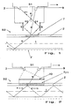
- Fig. 1 is a device for optical signal transmission in a schematic manner shown that a movable system S1 compared to a resting system System S2 shows.
- the resting system S2 consists of an optical fiber 1, which at least on their directly opposite the movable system S1 Surface provides a photorefractive layer 2.
- the lower dashed line 2 ' below the optical fiber 1 is only intended to indicate that the photorefractive layer 2 can completely enclose the optical fiber 1.
- the movable system S1 which is preferably moved at a constant distance via the stationary system S2 (see arrow direction), has a coherent light source 3, the light beam 31 of which is directed onto a beam splitter unit 4 which generates light beams 32 and 33 with the same intensity , Furthermore, mirrors 5, 6 are permanently connected to the movable system S1, on which the light beams 32 and 33 are reflected, so that they are superimposed in the region of the photorefractive layer 2.
- the interference pattern 7 which arises on the surface of the photorefractive layer 2 leads to a periodically variable refractive index within the photorefractive layer 2, by means of which a lattice structure is formed for the moment of exposure, at which the light beam 8, which is emitted from the light source 9 of the transmitting device , is deflected into the optical fiber 1, that the coupled light beam 8 'can be guided within the optical fiber by way of total reflection 10 (the dashed lines of the coupled light beam 8' provide total reflection at the boundary layer between air and photorefractive layer 9, since in unexposed state the refractive index n s of the photorefractive layer is identical to the refractive index n k of the optical fiber.
- An essential aspect of the device according to the invention is that the area of the interference pattern 7 on which is located in the photorefractive Layer 2 forms a diffraction grating simultaneously with the moving system S1 also moved, i.e. the photorefractive layer returns immediately after illumination back to its basic state and is the same if the appropriate material is selected the refractive index of the optical fiber.
- the movable system S1 has in addition to that provided for the signal transmission
- Light source 9 is an illuminating light source 3 for illuminating a mask 10, in which, for example, a sine grid is incorporated.
- the image of the mask on the photorefractive layer 2 in turn produces a sine grid 11 on the the light beam 8 in the positive and negative first order (see the coupled Rays 8 '(-I), 8 "(+ I)) is diffracted.
- the movable system S1 on which the mask 10 is firmly attached, moves parallel to the optical fiber 1 in the direction of the arrow, and each generates in the radiation field Light source 3, the light of which penetrates the mask 10, a dynamic diffraction grating, which is only limited to the narrowly limited area of the coupling point.
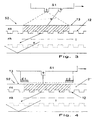
- Fig. 3 shows an optical fiber arrangement in which the optical fiber surface with a is physically incorporated structure 12, which is in the manner of a diffraction grating is trained.
- the optical fiber 1 is surrounded by a photorefractive layer 2, which has a smooth outside 13.
- the photorefractive layer 2 has the same refractive index as the optical fiber 1, whereby the boundary layer between optical fiber 1 and photorefractive layer 2 is optically ineffective.
- Light rays 8 coupled into the optical fiber occur unimpeded through the boundary layer and are on the surface of the photorefractive Layer 2 totally reflected.
- the photorefractive layer 2 is illuminated with the aid of a light source 3, whereby If they change their refractive index, the lattice structure 12 comes on the surface the optical fiber 1 optically to wear, at the coupled light 8 diffracted and is deflected into the interior of the optical fiber.
- FIG. 4 alternatively shows an arrangement in which, instead of the photorefractive layer 2 an electrosensitive material layer 2 "is used, the refractive index of which changes depending on an external electric field.
- electrosensitive material layer 2 an electrosensitive material layer 2 "is used, the refractive index of which changes depending on an external electric field.
- electrode bodies E1, E2 are attached, between which electrical ones are used Field lines run through which the refractive index of the electrically sensitive Layer 2 "is changed in the manner described above.
- FIG. 4 between electrodes E1 and E2 it reaches the electrically sensitive one Layer of light beam 8 striking the surface structure 12 on which the light beam is deflected into the interior of the optical fiber 1.
Landscapes
- Physics & Mathematics (AREA)
- Nonlinear Science (AREA)
- General Physics & Mathematics (AREA)
- Optics & Photonics (AREA)
- Optical Couplings Of Light Guides (AREA)
- Optical Communication System (AREA)
Description
- Fig. 1
- Ankoppelanordnung mit einer kohärenten Lichtquelle zur Erzeugung eines Interferenzmusters auf der Oberfläche einer photorefraktiven Schicht,
- Fig. 2
- Anordnung mit einer Maske zur Erzeugung eines Phasengitters innerhalb der photorefraktiven Schicht,
- Fig. 3
- Beleuchtungsprinzip mit einem fest an der Lichtleitfaseroberfläche eingebrachten Phasengitters sowie
- Fig. 4
- Anordnung mit elektrisch sensiblem Material über einer, ein Phasengitter aufweisende Lichtleitfaser.
- S1
- bewegliches System
- S2
- ruhendes System
- 1
- Lichtleitfaser
- 2
- photorefraktive Schicht
- 2'
- Oberfläche der photorefraktivem Schicht
- 2"
- elektrisch sensitive Schicht
- 3
- Lichtquelle
- 31, 32, 33
- Lichtstrahlen
- 4
- Strahlteilereinheit
- 5, 6
- Spiegel
- 7
- Interferenzmuster, Beugungsgitter
- 8
- Lichtstrahl
- 8'
- eingekoppelter Lichtstrahl
- 8' (-I)
- gebeugter Lichtstrahl der -1. Ordnung
- 8' (+I)
- gebeugter Lichtstrahl der +1. Ordnung
- 9
- Lichtquelle an der Sendeeinrichtung
- 10
- Maske
- 11
- Sinusgitter
- 12
- Oberflächenstruktur
- 13
- Außenseite der photorefraktiven Schicht
- E1, E2
- Elektrodenkörper
- ns
- Brechungsindex der photorefraktiven Schicht
- nk
- Brechungsindex der Lichtleitfaser
Claims (12)
- Vorrichtung zur optischen Signalübertragung, die aus einem ersten und zweiten System (S1, S2) besteht, die dynamisch entkoppelt sind und sich vorzugsweise relativ zueinander bewegen, mit wenigstens einer, eine erste Lichtquelle (9) aufweisenden Sendeeinrichtung, die auf dem ersten System (S1) angebracht ist, sowie einer, wenigstens eine Lichtleitfaser (1) aufweisenden Empfangseinrichtung, die auf dem zweiten System (S2) angebracht ist und entlang deren Erstreckung die erste Lichtquelle (9) bewegt wird und in die das Licht der ersten Lichtquelle (9) einkoppelbar ist,
dadurch gekennzeichnet, daß wenigstens auf der, der ersten Lichtquelle (9) unmittelbar gegenüberliegenden Oberfläche der Lichtleitfaser (1) eine photorefraktive Schicht (2) aufgebracht ist, und
daß am ersten System (S1) wenigstens eine kohärente Lichtquelle (3) angebracht ist, deren Licht durch Strahlüberlagerung am Ort der Lichteinkopplung ein optisches Gitter (7) in die photorefraktive Schicht (2) dynamisch einprägt, das über Beugungseigenschaften für das Licht der ersten Lichtquelle (9) verfügt, so daß deren Licht in die Lichtleitfaser (1) einkoppelbar ist. - Vorrichtung nach Anspruch 1,
dadurch gekennzeichnet, daß das Licht (31) der kohärenten Lichtquelle (9) auf einen Strahlteiler (4) trifft, durch den zwei getrennte Lichtstrahlen (32, 33) entstehen, die mittels einer Spiegelanordnung (5, 6) zur Überlagerung gebracht werden. - Vorrichtung nach Anspruch 1,
dadurch gekennzeichnet, daß wenigstens zwei kohärente Lichtquellen am ersten System (S1) vorgesehen sind, deren Lichtstrahlen unmittelbar zur Überlagerung gebracht werden. - Vorrichtung nach dem Oberbegriff des Anspruchs 1,
dadurch gekennzeichnet, daß wenigstens auf der, der ersten Lichtquelle (9) unmittelbar gegenüberliegenden Oberfläche der Lichtleitfaser (1) eine photorefraktive Schicht (2) aufgebracht ist, und
daß eine weitere Lichtquelle (3) sowie eine optische Maske (10) am ersten System (S1) derart vorgesehen sind, daß mittels Durchstrahlung der Maske (10) am Ort der Lichteinkoppelstelle ein optisches Gitter (7) in die photorefraktive Schicht (2) dynamisch eingeprägt wird, das über Beugungseigenschaften für das Licht der ersten Lichtquelle (9) verfügt, so daß deren Licht in die Lichtleitfaser (1) einkoppelbar ist. - Vorrichtung nach einem der Ansprüche 1 bis 4,
dadurch gekennzeichnet, daß sich das optische Gitter (7) durch Bestrahlung der photorefraktiven Schicht (2) lediglich an der aktuellen Einkoppelstelle zwischen der ersten Lichtquelle (9) und der mit der photorefraktiven Schicht (2) überzogenen Lichtleitfaser (1) ausbildet. - Vorrichtung nach dem Oberbegriff des Anspruchs 1,
dadurch gekennzeichnet, daß wenigstens in die, der ersten Lichtquelle (9) unmittelbar gegenüberliegende Oberseite der Lichtleitfaser (1) eine physikalisch ausgebildete Gitterstruktur (12) eingearbeitet ist,
daß auf der Gitterstruktur (12) eine optisch transparente Schicht (2) aufgebracht ist, die einen Brechungsindex aufweist, der dem Brechungsindex der Lichtleitfaser entspricht und deren Brechungsindex durch äußeren Energieeintrag veränderbar ist. - Vorrichtung nach Anspruch 6,
dadurch gekennzeichnet, daß die Gitterstruktur (12) über Beugungseigenschaften für das Licht der ersten Lichtquelle (9) verfügt, so daß das Licht in die Lichtleitfaser (1) einkoppelbar ist. - Vorrichtung nach Anspruch 6 oder 7,
dadurch gekennzeichnet, daß die optisch transparente Schicht (2) aus photorefraktivem Material besteht, das bei Bestrahlung mit Licht seinen Brechungsindex derart ändert, daß das von der ersten Lichtquelle (9) herrührende Licht die optisch transparente Schicht weitgehend verlustfrei durchdringt und durch die Gitterstruktur (12) in die Lichtleitfaser (1) mittels Beugung einkoppelbar ist. - Vorrichtung nach Anspruch 6 oder 7,
dadurch gekennzeichnet, daß die optisch transparente Schicht (2) aus elektrisch sensitivem Material besteht, das durch Anlegen einer äußeren Spannung seinen Brechungsindex ändert. - Vorrichtung nach Anspruch 9,
dadurch gekennzeichnet, daß Elektroden (E1, E2) um die Lichtleitfaser (1) derart angeordnet sind, daß in Abhängigkeit der aktuellen Einkoppelstelle der Brechungsindex derart änderbar ist, daß das von der ersten Lichtquelle (9) herrührende Licht die elektrisch sensitive Materialschicht (2") weitgehend verlustfrei durchdringt und durch die Gitterstruktur (12) in die Lichtleitfaser (1) mittels Beugung einkoppelbar ist. - Vorrichtung nach einem der Ansprüche 6 bis 10,
dadurch gekennzeichnet, daß die optisch transparente Schicht (12) an der der ersten Lichtquelle (9) gegenüberliegenden Oberseite glatt ausgebildet ist. - Vorrichtung nach einem der Ansprüche 1 bis 11,
dadurch gekennzeichnet, daß das erste (S1) und zweite System (S2) relativ zueinander rotierbar gelagert sind und die Anordnung als optischer Schleifring zur Signalübertragung zwischen den beiden Systemen dient.
Applications Claiming Priority (3)
| Application Number | Priority Date | Filing Date | Title |
|---|---|---|---|
| DE19730925 | 1997-07-17 | ||
| DE19730925 | 1997-07-17 | ||
| PCT/DE1998/001258 WO1999004309A1 (de) | 1997-07-17 | 1998-05-05 | Vorrichtung zur optischen signalübertragung zwischen zwei dynamisch entkoppelten systemen |
Publications (2)
| Publication Number | Publication Date |
|---|---|
| EP1002256A1 EP1002256A1 (de) | 2000-05-24 |
| EP1002256B1 true EP1002256B1 (de) | 2002-07-24 |
Family
ID=7836169
Family Applications (1)
| Application Number | Title | Priority Date | Filing Date |
|---|---|---|---|
| EP98925447A Expired - Lifetime EP1002256B1 (de) | 1997-07-17 | 1998-05-05 | Vorrichtung zur optischen signalübertragung zwischen zwei dynamisch entkoppelten systemen |
Country Status (6)
| Country | Link |
|---|---|
| US (1) | US6278815B1 (de) |
| EP (1) | EP1002256B1 (de) |
| JP (1) | JP2001510906A (de) |
| AU (1) | AU7756698A (de) |
| DE (1) | DE59804911D1 (de) |
| WO (1) | WO1999004309A1 (de) |
Families Citing this family (18)
| Publication number | Priority date | Publication date | Assignee | Title |
|---|---|---|---|---|
| DE19625870A1 (de) * | 1996-06-27 | 1998-01-08 | Schleifring & Apparatebau Gmbh | Vorrichtung zum Empfang optischer Signale mit einem lichtleitenden Gegenstand |
| US6246810B1 (en) | 1998-06-16 | 2001-06-12 | Electro-Tec Corp. | Method and apparatus for controlling time delay in optical slip rings |
| DE19917751C2 (de) * | 1999-04-20 | 2001-05-31 | Nokia Networks Oy | Verfahren und Überwachungsvorrichtung zur Überwachung der Qualität der Datenübertragung über analoge Leitungen |
| DE20021834U1 (de) | 2000-12-22 | 2001-03-15 | Schleifring und Apparatebau GmbH, 82256 Fürstenfeldbruck | Vorrichtung zur Lichteinkopplung in eine lichtleitende Schicht innerhalb einer hybrid aufgebauten elektrisch-optischen Leiterplatte |
| DE10160233B4 (de) * | 2001-02-02 | 2008-10-02 | Schleifring Und Apparatebau Gmbh | Vorrichtung zur Übertragung optischer Signale unter seitlicher Ankopplung an Lichtwellenleiter |
| DE102004037684B4 (de) | 2004-08-02 | 2006-09-21 | Schleifring Und Apparatebau Gmbh | Vorrichtungen zur optischen Drehübertragung mit freiem Innendurchmesser |
| DE50306043D1 (de) * | 2002-05-28 | 2007-02-01 | Schleifring Und Appbau Gmbh | Vorrichtung zur optischen signalübertragung zwischen zwei gegeneinander beweglichen einheiten |
| DE10240228B4 (de) * | 2002-05-28 | 2006-05-11 | Schleifring Und Apparatebau Gmbh | Vorrichtung zur optischen Signalübertragung zwischen zwei gegeneinander beweglichen Einheiten |
| DE10344875A1 (de) * | 2003-09-26 | 2005-04-28 | Siemens Ag | Datenübertragungsverfahren und Optischer Drehübertrager mit Durchführung |
| JP5021207B2 (ja) | 2003-10-29 | 2012-09-05 | カール・ツァイス・エスエムティー・ゲーエムベーハー | フォトリソグラフィにおける光学アセンブリ |
| DE10353891B4 (de) * | 2003-11-18 | 2007-03-29 | Jenoptik Laser Optik Systeme Gmbh | Anordnung zur Datenübertragung zwischen einem feststehenden und einem beweglichen Bauteil |
| DE102005010805B4 (de) * | 2005-03-07 | 2010-07-22 | Schleifring Und Apparatebau Gmbh | Vorrichtung zur Übertragung von von einem optischen Sender erzeugten modulierten optischen Signalen |
| DE102007041927A1 (de) | 2007-09-04 | 2009-03-12 | Siemens Ag | Vorrichtung zum Übertragen von Daten zwischen zwei zueinander beweglichen Systemen |
| JP5106167B2 (ja) * | 2007-10-12 | 2012-12-26 | 三菱電機株式会社 | 回転装置 |
| WO2014056524A1 (en) | 2012-10-09 | 2014-04-17 | Fraunhofer Gesellschaft Zur Förderung Der Angew. Forschung E.V. | Method and device for transmitting data |
| WO2015108531A1 (en) | 2014-01-17 | 2015-07-23 | Empire Technology Development Llc | Aligning guide using pressure-sensitive index change elastomer |
| WO2015163896A1 (en) * | 2014-04-24 | 2015-10-29 | Empire Technology Development Llc | Rewritable photorefractive polymer layer for optical fiber coupling |
| EP3776028B1 (de) | 2018-03-29 | 2025-10-22 | Fraunhofer-Gesellschaft zur Förderung der angewandten Forschung e.V. | Vorrichtung und verfahren zum übertragen von licht zwischen zumindest einem optoelektronischen bauelement und zumindest einem lichtwellenleiter |
Family Cites Families (4)
| Publication number | Priority date | Publication date | Assignee | Title |
|---|---|---|---|---|
| US4749248A (en) | 1985-11-06 | 1988-06-07 | American Telephone And Telegraph Company At&T Bell Laboratories | Device for tapping radiation from, or injecting radiation into, single made optical fiber, and communication system comprising same |
| DE3812203A1 (de) * | 1988-04-13 | 1989-10-26 | Fraunhofer Ges Forschung | Anordnung zur ein-/auskopplung von licht in/aus einem lichtwellenleiter |
| US5412743A (en) * | 1993-12-06 | 1995-05-02 | Eastman Kodak Company | Method and apparatus for amplitude modulation of a laser beam |
| WO1997026571A2 (en) * | 1996-01-18 | 1997-07-24 | British Telecommunications Public Limited Company | Optical waveguide with photosensitive refractive index cladding |
-
1998
- 1998-05-05 US US09/446,953 patent/US6278815B1/en not_active Expired - Fee Related
- 1998-05-05 AU AU77566/98A patent/AU7756698A/en not_active Abandoned
- 1998-05-05 DE DE59804911T patent/DE59804911D1/de not_active Expired - Fee Related
- 1998-05-05 WO PCT/DE1998/001258 patent/WO1999004309A1/de not_active Ceased
- 1998-05-05 EP EP98925447A patent/EP1002256B1/de not_active Expired - Lifetime
- 1998-05-05 JP JP2000503463A patent/JP2001510906A/ja active Pending
Also Published As
| Publication number | Publication date |
|---|---|
| US6278815B1 (en) | 2001-08-21 |
| WO1999004309A1 (de) | 1999-01-28 |
| EP1002256A1 (de) | 2000-05-24 |
| AU7756698A (en) | 1999-02-10 |
| JP2001510906A (ja) | 2001-08-07 |
| DE59804911D1 (de) | 2002-08-29 |
Similar Documents
| Publication | Publication Date | Title |
|---|---|---|
| EP1002256B1 (de) | Vorrichtung zur optischen signalübertragung zwischen zwei dynamisch entkoppelten systemen | |
| DE2740284C2 (de) | Kamera mit einer Anzeigevorrichtung | |
| DE69116166T2 (de) | Verfahren zur herstellung von optischen fasergittern | |
| DE3429947C2 (de) | ||
| DE69809358T2 (de) | Verfahren zum Schreiben von Bragg-Reflexionsgittern in Lichtwellenleitern | |
| DE2715311A1 (de) | Optische verbindungsvorrichtung | |
| EP3056934B1 (de) | Messkopf einer endoskopischen vorrichtung und verfahren zur inspektion und messung eines objektes | |
| EP1476716A1 (de) | Niederkoh renz-interferometrisches ger t zur lichtoptis chen abtastung eines objektes | |
| EP0877913B1 (de) | Vorrichtung zur messung der dicke transparenter gegenstände | |
| EP0876595A1 (de) | Niederkohärenz-interferometrisches gerät | |
| DE69822362T2 (de) | Raumfilter für einen Hochleistungslaserstrahl | |
| DE68916928T2 (de) | Optisches Element. | |
| DE102015218539B4 (de) | Optische Positionsmesseinrichtung | |
| DE3734438C2 (de) | ||
| DE10058239B4 (de) | Positionsmeßeinrichtung | |
| DE102007021774A1 (de) | Lichtmodulator zur Darstellung komplexwertiger Informationen | |
| DE3623265A1 (de) | Verfahren und anordnung zur faseroptischen messung einer weglaenge oder einer weglaengenaenderung | |
| EP0245198A1 (de) | Vorrichtung und Verfahren zur Erzeugung eines telezentrischen Lichtstrahls und Verfahren zur Herstellung eines holographischen Elements | |
| DE2526454C3 (de) | Spektrometer und Verfahren zur Untersuchung der spektralen Lichtzusammensetzung | |
| DE2758149B1 (de) | Interferometrisches Verfahren mit lambda /4-Aufloesung zur Abstands-,Dicken- und/oder Ebenheitsmessung | |
| EP1130439A2 (de) | Verfahren und Vorrichtung zur Beleuchtung eines transparenten Objekts | |
| EP4185915A2 (de) | Optisches system | |
| DE69730953T2 (de) | Diffraktionsführung für schrägeinfallinterferometer | |
| Luo et al. | Novel phase masks with overlapping regions to fabricate fiber Bragg gratings for filtering sky emission lines | |
| DE102020128173B3 (de) | Verfahren und Anordnung zur adaptierten Beleuchtung eines Objekts mit Licht |
Legal Events
| Date | Code | Title | Description |
|---|---|---|---|
| PUAI | Public reference made under article 153(3) epc to a published international application that has entered the european phase |
Free format text: ORIGINAL CODE: 0009012 |
|
| 17P | Request for examination filed |
Effective date: 20000315 |
|
| AK | Designated contracting states |
Kind code of ref document: A1 Designated state(s): DE ES FR GB IT NL SE |
|
| GRAG | Despatch of communication of intention to grant |
Free format text: ORIGINAL CODE: EPIDOS AGRA |
|
| 17Q | First examination report despatched |
Effective date: 20010907 |
|
| GRAG | Despatch of communication of intention to grant |
Free format text: ORIGINAL CODE: EPIDOS AGRA |
|
| GRAH | Despatch of communication of intention to grant a patent |
Free format text: ORIGINAL CODE: EPIDOS IGRA |
|
| GRAH | Despatch of communication of intention to grant a patent |
Free format text: ORIGINAL CODE: EPIDOS IGRA |
|
| GRAA | (expected) grant |
Free format text: ORIGINAL CODE: 0009210 |
|
| AK | Designated contracting states |
Kind code of ref document: B1 Designated state(s): DE ES FR GB IT NL SE |
|
| PG25 | Lapsed in a contracting state [announced via postgrant information from national office to epo] |
Ref country code: NL Free format text: LAPSE BECAUSE OF FAILURE TO SUBMIT A TRANSLATION OF THE DESCRIPTION OR TO PAY THE FEE WITHIN THE PRESCRIBED TIME-LIMIT Effective date: 20020724 |
|
| REG | Reference to a national code |
Ref country code: GB Ref legal event code: FG4D Free format text: NOT ENGLISH |
|
| GBT | Gb: translation of ep patent filed (gb section 77(6)(a)/1977) |
Effective date: 20020724 |
|
| REF | Corresponds to: |
Ref document number: 59804911 Country of ref document: DE Date of ref document: 20020829 |
|
| PG25 | Lapsed in a contracting state [announced via postgrant information from national office to epo] |
Ref country code: SE Free format text: LAPSE BECAUSE OF FAILURE TO SUBMIT A TRANSLATION OF THE DESCRIPTION OR TO PAY THE FEE WITHIN THE PRESCRIBED TIME-LIMIT Effective date: 20021024 |
|
| ET | Fr: translation filed | ||
| NLV1 | Nl: lapsed or annulled due to failure to fulfill the requirements of art. 29p and 29m of the patents act | ||
| PG25 | Lapsed in a contracting state [announced via postgrant information from national office to epo] |
Ref country code: ES Free format text: LAPSE BECAUSE OF FAILURE TO SUBMIT A TRANSLATION OF THE DESCRIPTION OR TO PAY THE FEE WITHIN THE PRESCRIBED TIME-LIMIT Effective date: 20030130 |
|
| PLBE | No opposition filed within time limit |
Free format text: ORIGINAL CODE: 0009261 |
|
| STAA | Information on the status of an ep patent application or granted ep patent |
Free format text: STATUS: NO OPPOSITION FILED WITHIN TIME LIMIT |
|
| 26N | No opposition filed |
Effective date: 20030425 |
|
| PGFP | Annual fee paid to national office [announced via postgrant information from national office to epo] |
Ref country code: FR Payment date: 20090527 Year of fee payment: 12 Ref country code: DE Payment date: 20090526 Year of fee payment: 12 |
|
| PGFP | Annual fee paid to national office [announced via postgrant information from national office to epo] |
Ref country code: GB Payment date: 20090527 Year of fee payment: 12 |
|
| PGFP | Annual fee paid to national office [announced via postgrant information from national office to epo] |
Ref country code: IT Payment date: 20090627 Year of fee payment: 12 |
|
| GBPC | Gb: european patent ceased through non-payment of renewal fee |
Effective date: 20100505 |
|
| REG | Reference to a national code |
Ref country code: FR Ref legal event code: ST Effective date: 20110131 |
|
| PG25 | Lapsed in a contracting state [announced via postgrant information from national office to epo] |
Ref country code: IT Free format text: LAPSE BECAUSE OF NON-PAYMENT OF DUE FEES Effective date: 20100505 |
|
| PG25 | Lapsed in a contracting state [announced via postgrant information from national office to epo] |
Ref country code: DE Free format text: LAPSE BECAUSE OF NON-PAYMENT OF DUE FEES Effective date: 20101201 |
|
| PG25 | Lapsed in a contracting state [announced via postgrant information from national office to epo] |
Ref country code: FR Free format text: LAPSE BECAUSE OF NON-PAYMENT OF DUE FEES Effective date: 20100531 |
|
| PG25 | Lapsed in a contracting state [announced via postgrant information from national office to epo] |
Ref country code: GB Free format text: LAPSE BECAUSE OF NON-PAYMENT OF DUE FEES Effective date: 20100505 |