EP1002239B1 - Radar-entfernungsmesseinrichtung - Google Patents
Radar-entfernungsmesseinrichtung Download PDFInfo
- Publication number
- EP1002239B1 EP1002239B1 EP98946287A EP98946287A EP1002239B1 EP 1002239 B1 EP1002239 B1 EP 1002239B1 EP 98946287 A EP98946287 A EP 98946287A EP 98946287 A EP98946287 A EP 98946287A EP 1002239 B1 EP1002239 B1 EP 1002239B1
- Authority
- EP
- European Patent Office
- Prior art keywords
- frequency
- target
- signal
- result
- mixing
- Prior art date
- Legal status (The legal status is an assumption and is not a legal conclusion. Google has not performed a legal analysis and makes no representation as to the accuracy of the status listed.)
- Expired - Lifetime
Links
- 238000005070 sampling Methods 0.000 claims description 21
- 238000001228 spectrum Methods 0.000 claims description 17
- 238000012545 processing Methods 0.000 claims description 11
- 238000005259 measurement Methods 0.000 claims description 10
- 230000009466 transformation Effects 0.000 claims description 6
- 230000010355 oscillation Effects 0.000 claims description 4
- 230000015572 biosynthetic process Effects 0.000 claims description 2
- 230000003247 decreasing effect Effects 0.000 claims description 2
- 238000003786 synthesis reaction Methods 0.000 claims description 2
- 230000005540 biological transmission Effects 0.000 description 17
- 238000010586 diagram Methods 0.000 description 8
- 239000000203 mixture Substances 0.000 description 5
- 238000011156 evaluation Methods 0.000 description 4
- 238000000034 method Methods 0.000 description 4
- 230000008569 process Effects 0.000 description 3
- 230000004044 response Effects 0.000 description 3
- 230000006872 improvement Effects 0.000 description 2
- 230000005855 radiation Effects 0.000 description 2
- 230000001105 regulatory effect Effects 0.000 description 2
- 230000003595 spectral effect Effects 0.000 description 2
- 230000002123 temporal effect Effects 0.000 description 2
- 230000007704 transition Effects 0.000 description 2
- 238000010521 absorption reaction Methods 0.000 description 1
- 238000011161 development Methods 0.000 description 1
- 230000018109 developmental process Effects 0.000 description 1
- 238000006073 displacement reaction Methods 0.000 description 1
- 230000000694 effects Effects 0.000 description 1
- 230000008030 elimination Effects 0.000 description 1
- 238000003379 elimination reaction Methods 0.000 description 1
- 238000009434 installation Methods 0.000 description 1
- 230000003993 interaction Effects 0.000 description 1
- 238000002310 reflectometry Methods 0.000 description 1
- 238000012549 training Methods 0.000 description 1
- 230000003313 weakening effect Effects 0.000 description 1
Images


Classifications
-
- G—PHYSICS
- G01—MEASURING; TESTING
- G01S—RADIO DIRECTION-FINDING; RADIO NAVIGATION; DETERMINING DISTANCE OR VELOCITY BY USE OF RADIO WAVES; LOCATING OR PRESENCE-DETECTING BY USE OF THE REFLECTION OR RERADIATION OF RADIO WAVES; ANALOGOUS ARRANGEMENTS USING OTHER WAVES
- G01S13/00—Systems using the reflection or reradiation of radio waves, e.g. radar systems; Analogous systems using reflection or reradiation of waves whose nature or wavelength is irrelevant or unspecified
- G01S13/02—Systems using reflection of radio waves, e.g. primary radar systems; Analogous systems
- G01S13/06—Systems determining position data of a target
- G01S13/08—Systems for measuring distance only
- G01S13/32—Systems for measuring distance only using transmission of continuous waves, whether amplitude-, frequency-, or phase-modulated, or unmodulated
- G01S13/34—Systems for measuring distance only using transmission of continuous waves, whether amplitude-, frequency-, or phase-modulated, or unmodulated using transmission of continuous, frequency-modulated waves while heterodyning the received signal, or a signal derived therefrom, with a locally-generated signal related to the contemporaneously transmitted signal
- G01S13/343—Systems for measuring distance only using transmission of continuous waves, whether amplitude-, frequency-, or phase-modulated, or unmodulated using transmission of continuous, frequency-modulated waves while heterodyning the received signal, or a signal derived therefrom, with a locally-generated signal related to the contemporaneously transmitted signal using sawtooth modulation
-
- G—PHYSICS
- G01—MEASURING; TESTING
- G01S—RADIO DIRECTION-FINDING; RADIO NAVIGATION; DETERMINING DISTANCE OR VELOCITY BY USE OF RADIO WAVES; LOCATING OR PRESENCE-DETECTING BY USE OF THE REFLECTION OR RERADIATION OF RADIO WAVES; ANALOGOUS ARRANGEMENTS USING OTHER WAVES
- G01S7/00—Details of systems according to groups G01S13/00, G01S15/00, G01S17/00
- G01S7/02—Details of systems according to groups G01S13/00, G01S15/00, G01S17/00 of systems according to group G01S13/00
- G01S7/35—Details of non-pulse systems
- G01S7/352—Receivers
- G01S7/354—Extracting wanted echo-signals
-
- G—PHYSICS
- G01—MEASURING; TESTING
- G01S—RADIO DIRECTION-FINDING; RADIO NAVIGATION; DETERMINING DISTANCE OR VELOCITY BY USE OF RADIO WAVES; LOCATING OR PRESENCE-DETECTING BY USE OF THE REFLECTION OR RERADIATION OF RADIO WAVES; ANALOGOUS ARRANGEMENTS USING OTHER WAVES
- G01S7/00—Details of systems according to groups G01S13/00, G01S15/00, G01S17/00
- G01S7/02—Details of systems according to groups G01S13/00, G01S15/00, G01S17/00 of systems according to group G01S13/00
- G01S7/40—Means for monitoring or calibrating
- G01S7/4004—Means for monitoring or calibrating of parts of a radar system
- G01S7/4008—Means for monitoring or calibrating of parts of a radar system of transmitters
-
- G—PHYSICS
- G01—MEASURING; TESTING
- G01S—RADIO DIRECTION-FINDING; RADIO NAVIGATION; DETERMINING DISTANCE OR VELOCITY BY USE OF RADIO WAVES; LOCATING OR PRESENCE-DETECTING BY USE OF THE REFLECTION OR RERADIATION OF RADIO WAVES; ANALOGOUS ARRANGEMENTS USING OTHER WAVES
- G01S7/00—Details of systems according to groups G01S13/00, G01S15/00, G01S17/00
- G01S7/02—Details of systems according to groups G01S13/00, G01S15/00, G01S17/00 of systems according to group G01S13/00
- G01S7/35—Details of non-pulse systems
- G01S7/352—Receivers
-
- G—PHYSICS
- G01—MEASURING; TESTING
- G01S—RADIO DIRECTION-FINDING; RADIO NAVIGATION; DETERMINING DISTANCE OR VELOCITY BY USE OF RADIO WAVES; LOCATING OR PRESENCE-DETECTING BY USE OF THE REFLECTION OR RERADIATION OF RADIO WAVES; ANALOGOUS ARRANGEMENTS USING OTHER WAVES
- G01S7/00—Details of systems according to groups G01S13/00, G01S15/00, G01S17/00
- G01S7/02—Details of systems according to groups G01S13/00, G01S15/00, G01S17/00 of systems according to group G01S13/00
- G01S7/35—Details of non-pulse systems
- G01S7/352—Receivers
- G01S7/356—Receivers involving particularities of FFT processing
Definitions
- the invention relates to a radar distance measuring device with a frequency-modulated, continuous High-frequency signal via an antenna to a to be determined Distance-transmitting object, with a signal derived from the transmitter on the one hand and via the Antenna or another antenna received echo signals from Target object, on the other hand, with a mixing stage that combines with each other, with a frequency analysis device for frequency analysis of the mixing result, with a first frequency analyzer to generate a rough analysis result and a another frequency analyzer with a refined sampling step is provided, as well as with a display device to display the frequency of the result of the mixing process appropriate distance.
- a distance resolution of 10 cm is required in known radar distance measuring devices to provide a frequency shift of 1.5 GHz according to the FMCW principle.
- bandwidth restrictions for example due to postal admission regulations If you select a smaller frequency deviation, the range resolution deteriorates corresponding to larger values.
- EP 0 425 006 describes a radar device with a a frequency-modulated, continuous high-frequency signal via an antenna at a distance to be determined located target object transmitter, with one from the transmitter derived signals on the one hand and via the antenna or a other antenna received echo signals from the target object on the other hand with a mixing stage combining with one another Frequency analysis device for frequency analysis of the mixing result, being a first frequency analyzer for generation a rough analysis result and another frequency analyzer provided with a refined sampling step is, and with a display device for displaying the one target-related frequency of the mixture result corresponding Distance described.
- the known Device several measurement cycles to be carried out to achieve a corresponding distance resolution.
- EP-A-0 647 857 describes a method which provides for a large number of measurement cycles in order to the measurement accuracy or the range resolution improve.
- the object of the invention is to be achieved a radar range finder short described general type so that with a limited frequency deviation of the frequency modulation of the Transmission signal achieved a high range resolution is carried out without a large number of measuring cycles must become.
- the frequency modulation of the frequency of the vibrating towards the target object perform extreme precision, preferably a linear or sawtooth-shaped frequency modulation is chosen.
- This modulation is done according to a very expedient embodiment of a radar distance measuring device of the kind specified here in such a way that an oscillator within a the sampling clock Signal processing corresponding period certain frequencies are regulated with high precision, these frequencies have values that correspond accordingly exactly on the desired frequency characteristic over the Time, with sawtooth modulation exactly on a straight line, are located. On details related to this discussed in more detail below.
- Another important improvement to a radar range finder of the type specified here is that beyond the frequency analysis Phase position of the determined, target-related frequency as a result of the Discrete Fourier Transform is preserved and evaluated, in the sense that that not to determine the distance to be measured only the full periods of the target-related frequency of the mixing result can be counted, but the corresponding multiple of the wavelength by that Fractions of the wavelength corresponding to phase angle is added.
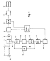
- the radar distance measuring device contains a transmitting / receiving antenna 1, for example in the form of a horn emitter, which has a transmitting / receiving switch 2 or a suitable type of coupler a frequency modulated oscillation from an oscillator 3 in the form of a voltage controlled oscillator is fed.
- the transmitting / receiving antenna 1 emits a transmission signal corresponding to a sawtooth Linear frequency modulation pulse, for example from 24.0 GHz to 25.5 GHz towards a target object 4, that is in the distance x to be determined from the Transmitting / receiving antenna is located.
- An echo signal reflected by the target object 4 Transmitted signal is received by antenna 1 and by a directional coupler of the switch 2 to a mixer 5 coupled out, which as a second input signal one coupled out by a directional coupler 6 Received part of the transmission signal. So while from Directional coupler 6 decoupled portion of the transmission signal arrives essentially directly at the mixer 5, has the reflected from target object 4 and Mixer 5 coupled out portion of the transmitter signal according to echo signals an electrical path length of 2x behind.
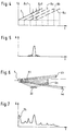
- the homodyne overlay made in mixer 5 therefore leads to the difference frequency on Mixer output, this difference frequency, as in Figure 4 shows qualitatively, between the through the Characteristic curve 7 marked transmission signal and by the characteristic curves 8a, 8b, 8c ... marked by Reflected objects from different distances, again essentially sawtooth-shaped frequency-modulated Echo signals is to be measured and added to determining distance x is directly proportional.
- the Connections in this regard are without the specialist more common.
- the output signal of the analog signal processing device 9 reaches an analog / digital converter 10, whose digital signals are digital Frequency analyzer 11 are supplied.
- This frequency analyzer generates in essentially a frequency spectrum of that of the analog / digital converter 10 digitized mixing results of the mixer 5.
- This frequency spectrum can the in Figure 5 have a qualitatively specified shape if the Radio frequency energy radiated from the transmitting / receiving antenna 1 for example in a limited period of time is linearly frequency modulated and as a sharply focused Beam hits a single target. That in such a case the frequency spectrum according to FIG 5 not a single frequency line corresponding to the contains the searched distance, based on the temporal Limiting the sawtooth-shaped pulse of the transmitter.
- the voltage controlled oscillator 3 receives a Control signal determining the frequency of its output signal via line 13 from a loop filter 14 in the form of an I or PI or PID controller, the input side the output signal of a comparator 15 is supplied becomes.
- This comparator 15 receives as an input signal a vibration or pulse train with a Frequency corresponding to the output frequency of the voltage controlled Oscillator 3 divided by the Divisor N.
- the second input signal to the comparator 15 is an oscillation or pulse train with a frequency response in accordance with the desired frequency modulation the output signal of the voltage controlled Oscillator 3 taking into account the through the frequency divider labeled 16 Divisors, this second input signal to Comparator 15 through direct digital synthesis in the DDS unit 17 is generated.
- the DDS unit 17 receives certain instantaneous frequencies corresponding to the frequency modulation Digital words, which lead to a high-precision specification of a frequency reference in the comparator 15.
- the Parts 13, 14, 15 and 16 thus form in the circuit 1 a phase-locked loop 19, the causes whenever the analog to digital converter 10 a digital sample of the mix result the mixer 5 takes, the voltage controlled Oscillator 3 at this time with high accuracy the transmission frequency according to the desired Has frequency response of the frequency modulation.
- the phase locked Loop 19 works fast enough to from sampling to sampling by the A / D converter 10 their control task for each new Points on the precise linear sawtooth curve of frequency modulation to fulfill.
- the divider 16 takes a frequency division into the 24 GHz MHz range and accordingly the output signal is also present the DDS unit in the MHz range.
- the comparator 15 takes a phase comparison or frequency comparison the output signals of components 16 and 17 before and causes readjustment of the output signal via the filter 14 of the voltage controlled oscillator 3 just a few Hz.
- Figure 6 shows a practical situation approximate situation between a transmitting / receiving antenna 1 and a number different large and at different distances from the antenna 1 located objects 4a, 4b, 4c ... and one located on the way between the antenna and the objects Object 20 of the environment.
- the transmit / receive antenna 1 practically does not produce a sharp bundled beam but a radiation fan 21 according to a certain directional characteristic of the spotlight used. Accordingly, the transmission / reception antenna receives 1 echo signals which different have electrical path lengths behind them, namely the Echo signals from those at different distances located target objects 4a to 4c, as well as echo signals, which after reflection, for example on the target object 4a the antenna 1 after further reflection on the object 20, which in turn leads to path lengths certain intermediate values.
- Figure 7 shows a frequency spectrum purely qualitatively the mixing result when evaluating the signals, as in a situation corresponding to FIG. 6 be received. It can be observed that target objects same size, which different distances from the transmitting / receiving antenna 1, with growing ones Intervals the transmit beam in increasing shade less and consequently that echo signals associated with individual target objects increasing target distance smaller amplitudes produce. In FIG. 8, this is one for a target object predetermined reflecting surface perpendicular to Direction of propagation of the transmitted signals shown. On such target object generated in the diagram of Figure 8, in which the logarithm of the amplitude over the Distance is plotted at the predetermined distance a maximum designated by 21. Will that Target moved closer to the transmitting / receiving antenna 1, so result from the geometric Conditions with a decreasing distance Increasing amplitude maxima, which are shown in FIG 22 and 23 are designated.
- the maxima 24 and 25 in the frequency spectrum or in the logarithm of the signal amplitude the distance according to FIGS. 7 and 8 are based on Reflections at transitions of the waveguide path or on the direct influence of the transmission signal the receive channel in the transmit / receive antenna 1 or in the switch 2 such that these maxima are not one correspond to the specific target object, its distance to the Transceiver antenna to be measured.
- the frequency spectrum of Figure 7 can besides that A maximum of 24 additional interference maxima in the range of low frequencies included, for example, of superstructures or installations in the area are caused and the evaluation of this spectrum are just as disruptive like reflections at line transitions. After this Interference maxima in some cases large amplitudes in the output of the Mixer 5 can reach, limit the possibility the capture of small goals, the maxima of which they overshadow.
- the analog signal processing device 9 in the corresponding Band-range filter 26 effective, for example So a bandstop filter for elimination in the lowest frequency range of the frequency spectrum interference maximum 24 located according to FIG. 7.
- the bandstop filter 26 of the analog signal processing device 9 is followed by a differentiator 27, which causes signal amplitudes to Reinforced and distant due to target objects Signal amplitudes due to target objects in increasingly short distances are weakened (Fiur 8, amplitude maxima 21, 22, 23).
- the differentiator 27 generates one to the frequency proportional gain, thus lifting the Weakening of the signal amplitude with increasing target distance, caused by the geometric Circumstances, on.
- the frequency analyzer 11 includes, as in FIG Figure 3 shown two frequency analyzers, namely in present embodiment a first frequency analyzer for fast Fourier transformation 29 and a second frequency analyzer for discrete Fourier transform 30.
- the FFT frequency analyzer 29 receives the digital signals from the output of the A / D converter 10 and delivers on the output side as a rough analysis result the information about the location of that scanning step about sampling the frequency spectrum towards which the target-related maximum of the spectrum generated by the FFT frequency analyzer 29 located.
- This information is used as a control signal for a digital bandpass filter device with group delay compensation 31 used, which is now from the A / D converter 10 digitized mixing result of the Mixer 5 one that is of interest to the target object Frequency containing and limited around this frequency Section of the mix result in the time domain selects which is then used for the DFT frequency analyzer 30 a discrete Fourier transform is carried out with a refined scanning step.
- the output of the FFT frequency analyzer 29 also serves to control the DFT frequency analyzer, as in Figure 3 is indicated.
- the refined sampling step of the Discrete Fourier Transform of the DFT frequency analyzer can for example one in the selected section by a factor 100 spectrally oversampling calculation of the discrete Provide Fourier transform, with the spectral line with the maximum amplitude in the frequency spectrum with a distance resolution correspondingly increased by a factor of 100 can be determined.
- Figure 9 makes the definitions of a and b in the above equation clear.
- the oversampling gives the refinement factor of the Sampling steps of the discrete Fourier transform compared to the Fast Fourier Transform.
- the factor a can be up to 100 and above.
- Discrete Fourier transformation is achieved a distance resolution down to the millimeter and Submillimeter range with comparatively short Computing times and without the use of multiple Computation cycles, being if the factor a is sufficiently large the measurement accuracy is chosen by the calculation accuracy is limited.
- the highly accurate dynamic setting the frequency of the voltage controlled Oscillator 3 in the manner described above in connection with the very precise determination of the target-related Frequency in the mix result of the Mixer 5 by the Discrete Fourier Transform in the DFT frequency analyzer 30 enables a to refine the distance resolution again, because the DFT frequency analyzer 30 not only the target-specific frequency of the mixing result, but also the phase position in the form of the complex Phase angle provides.
- the determination of the distance by the DFT frequency analysis yields a distance value of, for example, 10 m with an accuracy of 1 mm.
- the phase rotates 1,601 times through 360 °.
- Discrete Fourier transforms with different lengths can be calculated. For example can be omitted instead of 1,024 samples each of the first samples 1,010, 1,000 (etc.) samples be used, which marks the start of the Transmission frequency shifts to higher values. You get then the spectral line of interest in as possible middle position between the beginning and the end of a Sampling step of the discrete Fourier transform and thereby comes to a clear Phase determination.
- Radar range finders of those specified here Kind of reach at a measuring range of, for example 50 m a distance resolution in the submillimeter range.
- One use case is, for example Level measurement in closed containers.
- the evaluation the amplitude of the beat signal allows an interpretation in addition to the distance measurement about the type of target, such as reflectivity, Size, radiation absorption and the like, what in the Application example of a level measurement or level indicator can be of importance and statements about Type of container filling, surface quality of the Filling level and the like allows.
Landscapes
- Engineering & Computer Science (AREA)
- Radar, Positioning & Navigation (AREA)
- Remote Sensing (AREA)
- Computer Networks & Wireless Communication (AREA)
- Physics & Mathematics (AREA)
- General Physics & Mathematics (AREA)
- Radar Systems Or Details Thereof (AREA)
Description
- xn
- reeller Ausgangswert im Zeitbereich
- N
- Anzahl der Ausgangswerte
- Xm
- komplexer Ergebniswert im Frequenzbereich
- xn
- reeller Ausgangswert im Zeitbereich
- N
- Anzahl der Ausgangswerte
- Xm
- komplexer Ergebniswert im Frequenzbereich
Claims (12)
- Radar-Entfernungsmeßeinrichtung mit einem ein frequenzmoduliertes, kontinuierliches Hochfrequenzsignal über eine Antenne (1) auf ein in der zu bestimmenden Entfernung gelegenes Zielobjekt (4) richtenden Sender, mit einer vom Sender abgeleitete Signale einerseits und über die Antenne (1) bzw. eine weitere Antenne empfangene Echosignale vom Zielobjekt andererseits miteinander kombinierende Mischstufe (5), mit einer Frequenzanalysiereinrichtung (11) zur Frequenzanalyse des Mischungsergebnisses, wobei ein erster Frequenzanalysator zur Erzeugung eines Grob-Analyseergebnisses und ein weiterer Freguenzanalysator mit einem verfeinerten Abtastschritt vorgesehen ist, sowie mit einer Anzeigeeinrichtung (12) zur Anzeige der einer zielobjektbedingten Frequenz des Mischungsergebnisses entsprechenden Entfernung, dadurch gekennzeichnet, daß das Grob-Analyseergebnis zur Steuerung einer Filtereinrichtung (31) dient, welche einen die zielobjektbedingte Frequenz enthaltenden, um diese herum begrenzten Abschnitt des Mischungsergebnisses im Zeitbereich auswählt, über welchen mittels des weiteren Frequenzanalysators (30), der mit der Anzeigeeinrichtung (12) gekoppelt ist, eine diskrete Fourier-Transformation mit gegenüber dem Abtastschritt des ersten Frequenzanalysators (29) verfeinertem Abtastschritt durchgeführt wird.
- Einrichtung nach Anspruch 1, dadurch gekennzeichnet, daß das Hochfrequenzsignal des Senders linear frequenzmoduliert ist.
- Einrichtung nach Anspruch 1 oder 2, dadurch gekennzeichnet, daß das Mischungsergebnis der Mischstufe (5) von einem Analog-/Digitalwandler (10) digitalisiert wird, daß der erste Frequenzanalysator (29) eine digitale Schnelle Fouriertransformation durchführt und daß die Filtereinrichtung (31) ein digitaler, gruppenlaufzeitkompensierter Bandpaß ist.
- Einrichtung nach Anspruch 2 oder 3, dadurch gekennzeichnet, daß zwischen die Mischstufe (5) und den Analog-/Digital-Wandler (10) eine analoge Signalverarbeitungsschaltung (9) gelegt ist.
- Einrichtung nach Anspruch 4, dadurch gekennzeichnet, daß die analoge Signalverarbeitungsschaltung (9) mindestens einen Bandsperrfilter (26) zur Unterdrückung von Störfrequenzen im Frequenzspektrum des Ausgangssignals des Mischers (5) enthält.
- Einrichtung nach Anspruch 4 oder 5, dadurch gekennzeichnet, daß die analoge Signalverarbeitungsschaltung (9) einen Differenzierer (27) zur Verstärkung der Ausgangssignale des Mischers (5) in direkter Abhängigkeit von ihrer Frequenz enthält.
- Einrichtung nach einem der Ansprüche 4 bis 6, dadurch gekennzeichnet, daß die analoge Signalverarbeitungsschaltung (9) ein Antialiasingfilter (28) enthält.
- Einrichtung nach einem der Ansprüche 1 bis 7, dadurch gekennzeichnet, daß in der digitalen Frequenzanalysiereinrichtung (11) der weitere Frequenzanalysator (30) außer der Information über die zielobjekt bedingte Frequenz des Mischungsergebnisses der Mischstufe (5) ein Ausgangssignal entsprechend der Phasenlage der Schwingung entsprechend dieser Frequenz liefert, welches in einen entsprechenden Bruchteil der Wellenlängen dieser Frequenz in einer Recheneinrichtung umgerechnet und zu der aus der genannten zielobjektbedingten Frequenz errechneten Summe ganzer Wellenlänge zur Verfeinerung des Meßergebnisses hinzu addiert wird.
- Einrichtung nach einem der Ansprüche 1 bis 8, dadurch gekennzeichnet, daß die Abtastprobennahme des Mischungsergebnisses der Mischstufe (5) durch den bzw. einen Analog-/Digital-Wandler (10) unter Weglassung der ersten Abtastproben in mehreren Meßzyklen mit einer geringer werdenden Anzahl von Abtastproben durchgeführt wird derart, daß die zielobjektbedingte Frequenz im Mischungsergebnis der Mischstufe (5) etwa in die Mitte zwischen den Abtastschritten der Diskreten Fourier-Transformation zu liegen kommt.
- Einrichtung nach einem der Ansprüche 1 bis 9, dadurch gekennzeichnet, daß das frequenzmodulierte kontinuierliche Hochfrequenzsignal von einem spannungsgesteuerten Oszillator (3) erzeugt wird, dessen Abstimmspannung von einem Phasenkomparator (15) über einen Schleifenfilter (14), insbesondere in Gestalt eines I-Reglers oder eines PI-Reglers oder eines PID-Reglers, zugeführt (13) ist, wobei ein Eingangssignal zu dem Phasenkomparator (15) vom Ausgang des spannungsgesteuerten Oszillators (3) über einen Frequenzteiler (16) zugeführt ist, während das andere Eingangssignal zum Phasenkomparator (15) ein Frequenzsollwertsignal entsprechend einem dem Teilerverhältnis des Frequenzteilers (16) entsprechenden Bruchteil der Frequenz der Senderausgangsschwingung ist (PLL-Schaltung 19).
- Einrichtung nach Anspruch 10, dadurch gekennzeichnet, daß das dem Phasenkomparator (15) zugeleitete Frequenzsollwertsignal von einer Schaltungseinheit (17) zur direkten digitalen Synthese erzeugt wird, welche von einem Prozessor (18) Digitalwörter entsprechend aufeinanderfolgenden Frequenzwerten in Abhängigkeit von der Frequenzmodulation des Senders bezieht.
- Einrichtung nach Anspruch 10 oder 11, dadurch gekennzeichnet, daß zur linearen Frequenzmodulation des Hochfrequenzsignales dieses schrittweise und quasi stationär linear moduliert und während der Abtastschritte nachkalibriert wird.
Applications Claiming Priority (3)
| Application Number | Priority Date | Filing Date | Title |
|---|---|---|---|
| DE19734713 | 1997-08-11 | ||
| DE19734713A DE19734713A1 (de) | 1997-08-11 | 1997-08-11 | Radar-Entfernungsmeßeinrichtung |
| PCT/EP1998/004916 WO1999008128A1 (de) | 1997-08-11 | 1998-08-06 | Radar-entfernungsmesseinrichtung |
Publications (2)
| Publication Number | Publication Date |
|---|---|
| EP1002239A1 EP1002239A1 (de) | 2000-05-24 |
| EP1002239B1 true EP1002239B1 (de) | 2002-04-17 |
Family
ID=7838614
Family Applications (1)
| Application Number | Title | Priority Date | Filing Date |
|---|---|---|---|
| EP98946287A Expired - Lifetime EP1002239B1 (de) | 1997-08-11 | 1998-08-06 | Radar-entfernungsmesseinrichtung |
Country Status (5)
| Country | Link |
|---|---|
| US (1) | US6373427B1 (de) |
| EP (1) | EP1002239B1 (de) |
| JP (1) | JP3971573B2 (de) |
| DE (2) | DE19734713A1 (de) |
| WO (1) | WO1999008128A1 (de) |
Cited By (1)
| Publication number | Priority date | Publication date | Assignee | Title |
|---|---|---|---|---|
| CN111964773A (zh) * | 2020-07-22 | 2020-11-20 | 清华大学 | 一种基于多个交叠线性调频组的振动信号提取方法及装置 |
Families Citing this family (37)
| Publication number | Priority date | Publication date | Assignee | Title |
|---|---|---|---|---|
| US6317074B1 (en) * | 2000-06-15 | 2001-11-13 | Alliant Techsystems Inc. | High range resolution radar through non-uniform sampling |
| DE10053061A1 (de) * | 2000-10-26 | 2002-05-08 | Dornier Gmbh | Verfahren zur adaptiven Zielverarbeitung in einem kraftfahrzeugradar |
| US6693557B2 (en) * | 2001-09-27 | 2004-02-17 | Wavetronix Llc | Vehicular traffic sensor |
| US20040130482A1 (en) * | 2003-01-02 | 2004-07-08 | Yu-Shan Lin | Digital controlled linear sweep frequency mode for FMCW radar altimeter |
| US7426450B2 (en) | 2003-01-10 | 2008-09-16 | Wavetronix, Llc | Systems and methods for monitoring speed |
| US7239266B2 (en) * | 2004-08-26 | 2007-07-03 | Honeywell International Inc. | Radar altimeter |
| KR100776682B1 (ko) * | 2005-07-19 | 2007-11-16 | 한국전자통신연구원 | 초광대역 통신을 이용한 고정밀도 거리인식 장치 및 방법 |
| JP2006322912A (ja) * | 2005-09-07 | 2006-11-30 | Yamatake Corp | レーザ測長器およびレーザ測長方法 |
| US8248272B2 (en) * | 2005-10-31 | 2012-08-21 | Wavetronix | Detecting targets in roadway intersections |
| US8665113B2 (en) | 2005-10-31 | 2014-03-04 | Wavetronix Llc | Detecting roadway targets across beams including filtering computed positions |
| US20070192391A1 (en) * | 2006-02-10 | 2007-08-16 | Mcewan Thomas E | Direct digital synthesis radar timing system |
| DE112007001665B4 (de) * | 2006-10-06 | 2025-09-18 | Adc Automotive Distance Control Systems Gmbh | Radarsystem zur Umfelderfassung mit Mitteln zur Vermessung der Oszillatorkennlinie |
| US7405869B1 (en) * | 2007-05-02 | 2008-07-29 | Raytheon Company | Method and system of local oscillator signal generation |
| GB0717031D0 (en) * | 2007-08-31 | 2007-10-10 | Raymarine Uk Ltd | Digital radar or sonar apparatus |
| US8098193B2 (en) * | 2009-11-05 | 2012-01-17 | Honeywell International Inc. | Digitally controlled UWB millimeter wave radar |
| US8800363B2 (en) * | 2010-12-02 | 2014-08-12 | Rosemount Tank Radar Ab | Radar level gauge with dielectric rod connection |
| KR101806280B1 (ko) * | 2010-12-23 | 2017-12-07 | 재단법인 포항산업과학연구원 | Fmcw 기반 거리 측정기 |
| KR101404863B1 (ko) * | 2011-01-06 | 2014-06-09 | 주식회사 만도 | 물체 탐지 방법 및 그 레이더 시스템 |
| JP5730080B2 (ja) * | 2011-03-07 | 2015-06-03 | 古野電気株式会社 | レーダ信号処理装置、レーダ装置、レーダ信号処理プログラム及びレーダ信号処理方法 |
| US8866667B2 (en) | 2012-02-22 | 2014-10-21 | Honeywell International Inc. | High sensitivity single antenna FMCW radar |
| US9412271B2 (en) | 2013-01-30 | 2016-08-09 | Wavetronix Llc | Traffic flow through an intersection by reducing platoon interference |
| US9660605B2 (en) | 2014-06-12 | 2017-05-23 | Honeywell International Inc. | Variable delay line using variable capacitors in a maximally flat time delay filter |
| US10018716B2 (en) | 2014-06-26 | 2018-07-10 | Honeywell International Inc. | Systems and methods for calibration and optimization of frequency modulated continuous wave radar altimeters using adjustable self-interference cancellation |
| US9791560B2 (en) * | 2014-08-13 | 2017-10-17 | Infineon Technologies Ag | Radar signal processor, radar system and method for monitoring a functional safety of a radar system |
| DE102014111644A1 (de) * | 2014-08-14 | 2016-02-18 | Endress + Hauser Gmbh + Co. Kg | Vorrichtung zur Bestimmung des Füllstands eines Füllguts |
| US10145948B2 (en) * | 2016-07-13 | 2018-12-04 | Texas Instruments Incorporated | Methods and apparatus for narrowband ranging systems using coarse and fine delay estimation |
| CN106569189B (zh) * | 2016-10-31 | 2019-04-09 | 北京空间飞行器总体设计部 | 一种高分辨率sar卫星距离模糊度性能分析方法 |
| CN108398691B (zh) * | 2018-05-25 | 2023-10-17 | 中国工程物理研究院流体物理研究所 | 一种差频信号产生装置及方法 |
| US10859691B2 (en) * | 2018-08-22 | 2020-12-08 | Infineon Technologies Ag | Radar range accuracy improvement method |
| US11204410B2 (en) * | 2019-02-11 | 2021-12-21 | Nxp B.V. | Radar-based communication |
| CN110808791B (zh) * | 2019-10-15 | 2021-05-28 | 天津大学 | 基于分数阶傅里叶变换的线性调频信号的检测方法 |
| US11550027B2 (en) | 2020-05-04 | 2023-01-10 | Nxp B.V. | Predistortion technique for joint radar/communication systems |
| EP4071586A1 (de) | 2021-04-09 | 2022-10-12 | Fresenius Medical Care Deutschland GmbH | Berührungsloses bedienen medizintechnischer geräte |
| US12007465B2 (en) | 2021-10-19 | 2024-06-11 | Nxp B.V. | Radar apparatus and method with content embedded in the radar signal |
| CN115508784B (zh) * | 2022-09-14 | 2025-05-16 | 中国人民解放军海军航空大学 | 一种频率捷变雷达的发射频率控制装置及控制方法 |
| CN115685110B (zh) * | 2022-12-29 | 2023-04-28 | 北京华清瑞达科技有限公司 | 一种雷达回波模拟器高精度延时控制方法 |
| CN118444269B (zh) * | 2024-05-28 | 2025-08-08 | 浙江大学 | 一种提高地质雷达探测深度的分频补偿方法 |
Family Cites Families (25)
| Publication number | Priority date | Publication date | Assignee | Title |
|---|---|---|---|---|
| US3522527A (en) | 1967-09-13 | 1970-08-04 | British Iron Steel Research | Method and apparatus for measuring material thickness |
| US3628136A (en) | 1969-09-05 | 1971-12-14 | Garrett Corp | Means for measuring clearances in a gas turbine including a coaxial cable capacitor |
| GB1331525A (en) | 1971-08-19 | 1973-09-26 | Dn Znamei G Stvenny Uni Im 300 | Method and apparatus for gauging the thickness of flat metal products |
| FR2344031A1 (fr) * | 1976-03-12 | 1977-10-07 | Trt Telecom Radio Electr | Appareil a modulation de frequence destine a des mesures de distance de haute precision |
| US4211987A (en) | 1977-11-30 | 1980-07-08 | Harris Corporation | Cavity excitation utilizing microstrip, strip, or slot line |
| NL8102527A (nl) | 1981-05-22 | 1982-12-16 | Philips Nv | Kleurenbeeldbuis. |
| SU1103098A1 (ru) | 1982-08-24 | 1984-07-15 | Предприятие П/Я А-1209 | Частотный датчик давлени |
| JPS59169212A (ja) | 1983-03-16 | 1984-09-25 | Nec Corp | マイクロ波発振装置 |
| JPS6183946A (ja) | 1984-10-01 | 1986-04-28 | Kanzaki Paper Mfg Co Ltd | シ−ト状物質の配向測定方法 |
| JPS63145951A (ja) | 1986-12-09 | 1988-06-18 | Daipoole:Kk | 糸状材料の物性量測定装置 |
| JPH01163645A (ja) | 1987-12-21 | 1989-06-27 | Kanzaki Paper Mfg Co Ltd | シート状材料の高周波特性測定装置 |
| NL8902628A (nl) * | 1989-10-24 | 1991-05-16 | Hollandse Signaalapparaten Bv | Fm-cw radarapparaat. |
| DE4040084C2 (de) | 1990-12-14 | 1998-09-24 | Dittel Walter Luftfahrt | Berührungsloses Abstandsmeßgerät |
| EP0558759A1 (de) | 1991-09-20 | 1993-09-08 | Dipole Electronics Co. Ltd. | Vorrichtung zum messen einer physikalischen grösse |
| US5325095A (en) | 1992-07-14 | 1994-06-28 | The United States Of America As Represented By The United States Department Of Energy | Stepped frequency ground penetrating radar |
| US5396250A (en) * | 1992-12-03 | 1995-03-07 | The United States Of America As Represented By The Secretary Of The Air Force | Spectral estimation of radar time-of-arrival periodicities |
| JP2746061B2 (ja) | 1993-07-09 | 1998-04-28 | 日本電気株式会社 | 音声パケット交換装置 |
| DE4324745C2 (de) * | 1993-07-23 | 1996-04-25 | Daimler Benz Aerospace Ag | Radarempfänger für ein frequenzmoduliertes Dauerstrich-Radargerät |
| DE4334079C2 (de) * | 1993-10-06 | 1997-02-13 | Daimler Benz Aerospace Ag | Hochgenauer Radar-Entfernungsmesser |
| FR2718249B1 (fr) * | 1994-04-05 | 1996-04-26 | Thomson Csf | Procédé et dispositif radar de mesure de distance. |
| EP0730166B1 (de) * | 1995-03-03 | 2001-06-27 | Siemens Aktiengesellschaft | Verfahren und Anordnung zur Verkehrserfassung mit einem Radargerät |
| US5596325A (en) | 1995-07-07 | 1997-01-21 | Nonlinear Technologies, Inc. | FM-CW radar transceiver |
| DE19543179A1 (de) | 1995-11-20 | 1997-05-22 | Forschungszentrum Juelich Gmbh | Mikrowellenresonator, Verfahren zur Herstellung eines solchen Resonators sowie Verfahren zur Kompensation des Temperaturkoeffizienten der Resonanzfrequenz eines Mikrowellenresonators |
| EP0887658B1 (de) * | 1997-06-27 | 2004-08-25 | EADS Deutschland GmbH | Füllstandmessradargerät |
| DE19833220A1 (de) | 1997-12-15 | 1999-06-17 | Mikrowellen Technologie Und Se | Abstandsmeßvorrichtung und Verfahren zur Bestimmung eines Abstandes |
-
1997
- 1997-08-11 DE DE19734713A patent/DE19734713A1/de not_active Withdrawn
-
1998
- 1998-08-06 EP EP98946287A patent/EP1002239B1/de not_active Expired - Lifetime
- 1998-08-06 US US09/485,380 patent/US6373427B1/en not_active Expired - Lifetime
- 1998-08-06 WO PCT/EP1998/004916 patent/WO1999008128A1/de not_active Ceased
- 1998-08-06 DE DE59803873T patent/DE59803873D1/de not_active Expired - Lifetime
- 1998-08-06 JP JP2000506541A patent/JP3971573B2/ja not_active Expired - Lifetime
Cited By (1)
| Publication number | Priority date | Publication date | Assignee | Title |
|---|---|---|---|---|
| CN111964773A (zh) * | 2020-07-22 | 2020-11-20 | 清华大学 | 一种基于多个交叠线性调频组的振动信号提取方法及装置 |
Also Published As
| Publication number | Publication date |
|---|---|
| DE59803873D1 (de) | 2002-05-23 |
| EP1002239A1 (de) | 2000-05-24 |
| DE19734713A1 (de) | 1999-02-18 |
| JP3971573B2 (ja) | 2007-09-05 |
| JP2001512839A (ja) | 2001-08-28 |
| US6373427B1 (en) | 2002-04-16 |
| WO1999008128A1 (de) | 1999-02-18 |
Similar Documents
| Publication | Publication Date | Title |
|---|---|---|
| EP1002239A1 (de) | Radar-entfernungsmesseinrichtung | |
| EP0677172B1 (de) | Computerisiertes radarverfahren zur messung von abständen und relativgeschwindigkeiten zwischen einem fahrzeug und vor ihm befindlichen hindernissen | |
| EP2044459B1 (de) | Winkelauflösender radarsensor | |
| DE69730416T2 (de) | Füllstandmessradargerät | |
| EP0727051B1 (de) | Radargerät und verfahren zu seinem betrieb | |
| EP0499952B1 (de) | FMCW-Radarsystem mit linearer Frequenzmodulation | |
| DE4242700C2 (de) | Verfahren zur Messung des Abstandes und der Geschwindigkeit von Objekten | |
| DE69214883T2 (de) | Vorrichtung zur Bereichseinstellung bei FM-Dauerwelle-Radar | |
| DE112005000763B4 (de) | Radarsystem | |
| EP1984707B1 (de) | Paarweise zf-abtastung für puls-laufzeit-füllstandsensoren | |
| DE69923815T2 (de) | FM-CW Radarvorrichtung | |
| DE3038961C2 (de) | ||
| DE69019292T2 (de) | Dauerstrich-FM-Radargerät. | |
| EP3084464B1 (de) | Prf-frequenzgenerator für ein füllstandsmessgerät | |
| DE3787015T2 (de) | Im frequenzbereich wirkendes impulsraffungsradargerät zur störechobeseitigung. | |
| EP3538922A1 (de) | Radarsensor für kraftfahrzeuge | |
| WO1994014037A1 (de) | Mit mikrowellen arbeitendes füllstandsmessgerät | |
| EP0965052B1 (de) | Verfahren zum betrieb eines sensorsystems und sensorsystem | |
| DE4345242A1 (de) | Frequenzumsetzungsschaltung für ein Radar-Abstandsmeßgerät | |
| WO2016180675A1 (de) | Radarvorrichtung | |
| EP0848830A2 (de) | Vorrichtung zur abstandsmessung | |
| EP3418699B1 (de) | Füllstandradargerät mit gesteuerter sendeleistung | |
| DE2756413C3 (de) | Gerät zur Messung des Abstandes und der Näherungsgeschwindigkeit oder der Entfernungsgeschwindigkeit eines beweglichen Zieles | |
| EP3418698B1 (de) | Füllstandreflektometer mit referenzreflexion | |
| DE29723245U1 (de) | Radar-Entfernungsmeßeinrichtung |
Legal Events
| Date | Code | Title | Description |
|---|---|---|---|
| PUAI | Public reference made under article 153(3) epc to a published international application that has entered the european phase |
Free format text: ORIGINAL CODE: 0009012 |
|
| 17P | Request for examination filed |
Effective date: 20000210 |
|
| AK | Designated contracting states |
Kind code of ref document: A1 Designated state(s): DE FR GB IT |
|
| 17Q | First examination report despatched |
Effective date: 20000824 |
|
| GRAG | Despatch of communication of intention to grant |
Free format text: ORIGINAL CODE: EPIDOS AGRA |
|
| GRAG | Despatch of communication of intention to grant |
Free format text: ORIGINAL CODE: EPIDOS AGRA |
|
| GRAH | Despatch of communication of intention to grant a patent |
Free format text: ORIGINAL CODE: EPIDOS IGRA |
|
| REG | Reference to a national code |
Ref country code: GB Ref legal event code: IF02 |
|
| GRAH | Despatch of communication of intention to grant a patent |
Free format text: ORIGINAL CODE: EPIDOS IGRA |
|
| GRAA | (expected) grant |
Free format text: ORIGINAL CODE: 0009210 |
|
| AK | Designated contracting states |
Kind code of ref document: B1 Designated state(s): DE FR GB IT |
|
| PG25 | Lapsed in a contracting state [announced via postgrant information from national office to epo] |
Ref country code: IT Free format text: LAPSE BECAUSE OF FAILURE TO SUBMIT A TRANSLATION OF THE DESCRIPTION OR TO PAY THE FEE WITHIN THE PRESCRIBED TIME-LIMIT;WARNING: LAPSES OF ITALIAN PATENTS WITH EFFECTIVE DATE BEFORE 2007 MAY HAVE OCCURRED AT ANY TIME BEFORE 2007. THE CORRECT EFFECTIVE DATE MAY BE DIFFERENT FROM THE ONE RECORDED. Effective date: 20020417 |
|
| REF | Corresponds to: |
Ref document number: 59803873 Country of ref document: DE Date of ref document: 20020523 |
|
| GBT | Gb: translation of ep patent filed (gb section 77(6)(a)/1977) |
Effective date: 20020719 |
|
| ET | Fr: translation filed | ||
| PLBE | No opposition filed within time limit |
Free format text: ORIGINAL CODE: 0009261 |
|
| STAA | Information on the status of an ep patent application or granted ep patent |
Free format text: STATUS: NO OPPOSITION FILED WITHIN TIME LIMIT |
|
| 26N | No opposition filed |
Effective date: 20030120 |
|
| REG | Reference to a national code |
Ref country code: FR Ref legal event code: CD Ref country code: FR Ref legal event code: CA |
|
| REG | Reference to a national code |
Ref country code: DE Ref legal event code: R082 Ref document number: 59803873 Country of ref document: DE Representative=s name: KUNZ, HERBERT, DIPL.-PHYS. DR.RER.NAT., DE Ref country code: DE Ref legal event code: R082 Ref document number: 59803873 Country of ref document: DE Representative=s name: DR. KUNZ & KOLLEGEN PATENTANWALTSKANZLEI, DE Ref country code: DE Ref legal event code: R082 Ref document number: 59803873 Country of ref document: DE |
|
| REG | Reference to a national code |
Ref country code: DE Ref legal event code: R082 Ref document number: 59803873 Country of ref document: DE Representative=s name: KUNZ, HERBERT, DIPL.-PHYS. DR.RER.NAT., DE |
|
| REG | Reference to a national code |
Ref country code: DE Ref legal event code: R082 Ref document number: 59803873 Country of ref document: DE Representative=s name: KUNZ, HERBERT, DIPL.-PHYS. DR.RER.NAT., DE |
|
| REG | Reference to a national code |
Ref country code: DE Ref legal event code: R082 Ref document number: 59803873 Country of ref document: DE Representative=s name: KUNZ, HERBERT, DIPL.-PHYS. DR.RER.NAT., DE |
|
| REG | Reference to a national code |
Ref country code: FR Ref legal event code: PLFP Year of fee payment: 19 |
|
| REG | Reference to a national code |
Ref country code: FR Ref legal event code: PLFP Year of fee payment: 20 |
|
| PGFP | Annual fee paid to national office [announced via postgrant information from national office to epo] |
Ref country code: DE Payment date: 20170822 Year of fee payment: 20 Ref country code: FR Payment date: 20170822 Year of fee payment: 20 Ref country code: GB Payment date: 20170822 Year of fee payment: 20 |
|
| REG | Reference to a national code |
Ref country code: DE Ref legal event code: R071 Ref document number: 59803873 Country of ref document: DE |
|
| REG | Reference to a national code |
Ref country code: GB Ref legal event code: PE20 Expiry date: 20180805 |
|
| PG25 | Lapsed in a contracting state [announced via postgrant information from national office to epo] |
Ref country code: GB Free format text: LAPSE BECAUSE OF EXPIRATION OF PROTECTION Effective date: 20180805 |