EP1001321A2 - Control of an electrical device - Google Patents
Control of an electrical device Download PDFInfo
- Publication number
- EP1001321A2 EP1001321A2 EP99120495A EP99120495A EP1001321A2 EP 1001321 A2 EP1001321 A2 EP 1001321A2 EP 99120495 A EP99120495 A EP 99120495A EP 99120495 A EP99120495 A EP 99120495A EP 1001321 A2 EP1001321 A2 EP 1001321A2
- Authority
- EP
- European Patent Office
- Prior art keywords
- control
- control unit
- electrical device
- electrical
- separate
- Prior art date
- Legal status (The legal status is an assumption and is not a legal conclusion. Google has not performed a legal analysis and makes no representation as to the accuracy of the status listed.)
- Granted
Links
Images
Classifications
-
- F—MECHANICAL ENGINEERING; LIGHTING; HEATING; WEAPONS; BLASTING
- F24—HEATING; RANGES; VENTILATING
- F24C—DOMESTIC STOVES OR RANGES ; DETAILS OF DOMESTIC STOVES OR RANGES, OF GENERAL APPLICATION
- F24C7/00—Stoves or ranges heated by electric energy
- F24C7/08—Arrangement or mounting of control or safety devices
- F24C7/082—Arrangement or mounting of control or safety devices on ranges, e.g. control panels, illumination
-
- G—PHYSICS
- G05—CONTROLLING; REGULATING
- G05B—CONTROL OR REGULATING SYSTEMS IN GENERAL; FUNCTIONAL ELEMENTS OF SUCH SYSTEMS; MONITORING OR TESTING ARRANGEMENTS FOR SUCH SYSTEMS OR ELEMENTS
- G05B19/00—Programme-control systems
- G05B19/02—Programme-control systems electric
- G05B19/04—Programme control other than numerical control, i.e. in sequence controllers or logic controllers
- G05B19/042—Programme control other than numerical control, i.e. in sequence controllers or logic controllers using digital processors
- G05B19/0423—Input/output
Definitions
- the invention relates to a control for an electrical device with at least one electrical contained in the device Functional device, wherein the controller at least one Power switching device contains.
- the Invention application to an electric heating device, in particular a household electric cooker or oven.
- DE-U 296 22 066 proposes a domestic appliance, which is being expanded the usual design at least one separate operating and / or Display element is assigned. This is similar to the Functional principle forth for example a remote control for a television in which, so to speak, from the electrical appliance separate control buttons or switches are included. In addition, there is a bidirectional data transmission provided to be on a separate from the electrical device Read off display-relevant data.
- DE 196 15 357 contains solutions have been proposed, where only separate display elements provided for the operating state of the electrical device are the program parameters set on the electrical device get saved and then the corresponding one Reconstruct and display the program flow internally.
- EP 846 991 describes a household appliance network a central control computer for monitoring. For improved This central monitoring is the availability of information with a mobile display device on one side Telecontrol technology connected.
- a display device transmits data relating to the defect via the transmission device and telephone network to a diagnostic center, in particular a computer at a customer service center or the like
- the invention has for its object one described above To create control that the disadvantages of State of the art avoids the operation of electrical devices improved and diverse applications opened.
- the controller has one of the electrical devices separate, separable or removable control unit, which wirelessly transmit signals with the electrical device connected is.
- wireless or contactless telecontrol technologies can for example connect to infrared or by means of electromagnetic waves.
- the separate control unit essentially contains the Control and regulation part for the electrical device that the at least one power switching device, preferably is installed in the electrical device. Is preferred the entire control and regulation part in the control unit arranged, except for sensors contained in the electrical device o.
- the measured or control variables deliver. So it happens a spatial separation of the control into a power switching part, who sits in the electrical device, and a control and Control part, which is arranged in the separate control unit is.
- the control unit can have a processing device, preferably at least one microprocessor. This processing facility can essentially the control and regulation part form for the electrical appliance.
- the control unit advantageously has input means for input assigned by control commands and the like, in particular Switches such as touch switches, rotary switches and / or pressure switch.
- the control unit is preferably housed with the input means in a control panel, the but a full-fledged one compared to conventional remote controls Can be remote control.
- the controller can have a memory in which among other things different program sequences for the Control and / or parameters of evaluation functions of the Electrical device can be stored. Such parameters of evaluation functions can, for example, when setting up the Electrical device can be determined and stored. Possible is also a storage of series-specific Electrical appliance data.
- Transmission devices can be in the electrical device and Control unit for wireless signal transmission for or exist within the control. Preferably work the transmission devices bidirectional, that means both in the control unit and in that in the electrical device seated part of the controller is both a transmit and also a receiving device installed. It is possible that the control display means for displaying the operating state assigned to the control and / or the electrical device are preferably arranged in the separate control unit are. Display means can, for example, simple illuminated displays, LC displays as well as alphanumeric displays.
- the electrical device can be equipped with sensors for monitoring the Operating state, for example one of the functional units, be provided.
- the signals from such sensors can be on the controller or the control unit are given, the thus, for example, control loops for the electrical device can form, or these operating states by means of display on the control unit for informing a user represent.
- the controller and / or the electrical device can be a location detection device to record the spatial assignment the control unit to the electrical device.
- the spatial Assignment can, for example, be at least one certain position of the control unit according to direction / distance be given, which is essentially a precise location or can be a limited area. It is possible that Control unit, for example, within a certain Detect distance to the electrical device.
- An alternative can be a specific position of the control unit, in particular on the top of the electrical device itself or a place freely accessible to a user. This particular Position can be marked, for example optically by means of colored markings or mechanical stops or rest.
- Such a location detection device makes it possible, for example, only then with the control unit to operate when the control unit in the specific position is. This allows incorrect operation as well as operation by unintended users, for example by avoid children playing on a household appliance; the Control unit is simply separated from the device on one kept in an inaccessible place.
- a contactless location detection device in particular wireless with a transmitter and a receiver, wherein the receiving device is preferably in the Control unit is included.
- Contactless can be preferred here mean that the location recording without any contact to the Capture works in itself.
- the location detection device can work inductively, for example.
- An alternative to a location detection device can be a with the electrical device and / or the control system connected and attached to a predetermined position Station and / or bracket on which the control unit What is to be communicated to the controller must be attached.
- a particularly easy detection of a station attached Control unit can be done by actuated contacts.
- Control unit can be holding means for detachable without tools Fixation can be provided in a certain position.
- This Holding means can preferably be magnetic holding means and / or have magnetic alignment means. these can advantageous under smooth, unbroken surfaces such as For example, glass surfaces or the like are attached.
- the Holding means can also be part of a location detection device for the control unit.
- the control unit can be equipped with a own source, preferably one again rechargeable energy storage, such as an accumulator.
- Prefers becomes a power supply with which the control unit can be released is connectable, such a connection preferably a specific spatial assignment of the control unit to the Electrical device conditional. Accordingly, the control unit can only work when it is supplied with energy for which it is must be in a particular position described above.
- a Double function of the transmission devices for example with separate transmission windows, reduces the effort.
- the controller can, especially in the in the electrical device contained part, contain a power switching device, those for interacting with different control units or types of control units.
- These different Control units each contain the control and Control part for the electrical device, being different Functional features with regard to equipment, control options or the like. That way it is possible, both simple control units with pure controls to be provided as well as further upgraded control units, the additional functions such as timers, program sequences etc. have.
- a basic version of an electrical device can be individually retrofitted or upgraded, all the additional functions required as an upgrade are realized in the control unit.
- a control according to the invention can be particularly preferred in an electric heater with a cooktop can be installed, which consists in particular of glass ceramic.
- One described above separate control unit can go to a given location Can be positioned on the hob and thus like one this point fixed operating unit act.
- Advantageous the electrical device can only be used in this position Control unit operated or operated.
- Another advantage of the present invention is that in the event of a malfunction or irreparable damage the entire electrical device including the control system must be replaced, but only the electrical device or the control unit.
- part of the invention is a remotely controllable Electrical device, in particular with one described above
- Control controllable the at least one power switching device contains and essentially free of controls and / or control and regulation parts. It can with different types of control units through wireless Signal transmission can be controlled, these control units are designed as separate units from the electrical device and all control and regulation parts for the electrical device contain.
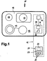
- the drawing shows schematically an electric stove with a controller that is separate from the electrical device Has control unit.
- FIG. 1 shows an electric cooking appliance 11 with a hob 12, the heaters 13 and, by a surrounding Dash-dotting marked as a functional unit, an inventive control 15.
- the schematic held drawing contains the cooking device 11, a power switching device 17, either one or all heaters 13 charged with performance. Your control commands receives the power switching device 17 from the first Transmission device 18, with which it is shown connected is.
- the transmission device 18 is located under a dash mark 19 shown in dashed lines lower right part of the hob 12.
- the electric cooking device 11, or in particular the first transmission device 18, is a separate control unit 21 assigned a second transmission device shown in dashed lines 22, a processing device 23 and Has input and output means 25.
- the second transmission device 22 interacts with the first transmission device 18.
- the processing device 23 preferably has including a microprocessor and a memory for Parameters and / or operations.
- the input and output means 25 can be various switches, for example Touch switches and displays, for example illuminated displays or alphanumeric displays.
- the electric cooking appliance 11 via data transmission between the transmission facilities 18 and 22 and the power switching device 17 are operated or controlled.
- the control commands and / or the operating state of the electric cooking appliance can be connected to the input and Output means 25 are displayed.
- a locking or precise Adherence to the position can on the one hand by stops o.
- a magnetic is advantageous Fixation possible that does not interrupt the smooth surface of the hob 12 is required.
- a location detection device 26 can be a proximity switch, a mechanical switch, or for example a be an inductive sensor.
- This location detection device 26 can be a proximity switch, a mechanical switch, or for example a be an inductive sensor.
- Touch-up mark 19 on the hob 12 are other locations for the control unit 21 is conceivable, on which an attachment is detected and as a prerequisite for operating the electric cooking appliance 11 can be used.
- the control unit 21 contains prefers the entire control and regulation part for that Electric cooking appliance.
- the control unit 21 is in a desired geometric position, is an operation of the Electric cooking appliance 11 only possible. On the one hand, this can by an internal lock, for example in the processing device 23, take place.
- Alternative types of transmission are infrared, Ultrasound, radio or the like
- Control commands from the processing device 23 in Switching commands are implemented, which via the transmission devices 22 and 18 to the power switching device 17 are given. According to the orders, this applies to the Heaters 13.
- the control commands may well under Use information formed from the electrical device become.
- On an output means 25 of the control unit for example one set at a certain level Heater 13 displayed.
- An advantage of the present invention is that, in order to expand the variety of functions of the electrical device 11, only the separate control unit 21 can be replaced got to. For example, in a new control unit Additional functions such as timers, automatic cooking or different program sequences, different pot detection functions or the like. An exchange of the determining part of the controller 15 is in this way simply possible.
- the electric cooking device 11 or the heating devices 13 can sensor devices (not shown) can be assigned, for example temperature sensors or protectors.
- Means the temperature sensors can, for example, be the temperature a heating device 13 can be detected and via the transmission devices 18 and 22 to the control unit 21 and the Processing device 23 are transferred. This information can be used to activate a hot display or for automatic Cooking processes can be used. Protectors are also possible, but in an emergency, the power supply directly to interrupt the heater.
- a power supply to the control unit 21 can either by batteries or accumulators. Alternatively, an inductive power supply is available on the Attachment mark 19 of control unit 21 placed on it. An inductive energy supply can possibly be used in window operation via an inductive data interface.
- a single control unit 21 can be used for a complete family of devices (Hob, oven, extractor hood, microwave oven, etc.) can be used.
- a change can be made either Switching on the control unit or by changing the Touch-up mark or a given position respectively.
- To rationalize the manufacturing process can standardize a few basic models of electric cooking appliances 11 be built up by means of different Control units of different values or equipped Electric cookers result. This has the advantage that before all the power switching devices 17 for a variety be carried out in the same way by different electric cooking appliances can.
- Certain switching or display functions can be carried out on the electrical device are left, for example a general one ON / OFF switch, state lock switch for an Removal of the control unit during operation or hot indicator for a hot heater.
Landscapes
- Engineering & Computer Science (AREA)
- General Physics & Mathematics (AREA)
- Combustion & Propulsion (AREA)
- Mechanical Engineering (AREA)
- General Engineering & Computer Science (AREA)
- Physics & Mathematics (AREA)
- Chemical & Material Sciences (AREA)
- Automation & Control Theory (AREA)
- Electric Stoves And Ranges (AREA)
- Induction Heating Cooking Devices (AREA)
- Selective Calling Equipment (AREA)
- Cookers (AREA)
- Control Of Electric Motors In General (AREA)
- Apparatus For Making Beverages (AREA)
Abstract
Description
Die Erfindung betrifft eine Steuerung für ein Elektrogerät mit wenigstens einer in dem Gerät enthaltenen elektrischen Funktionseinrichtung, wobei die Steuerung wenigstens eine Leistungsschalteinrichtung enthält. Bevorzugt findet die Erfindung Anwendung bei einem Elektrowärmegerät, insbesondere einem Haushaltselektroherd oder einem Haushaltsbackofen.The invention relates to a control for an electrical device with at least one electrical contained in the device Functional device, wherein the controller at least one Power switching device contains. Preferably the Invention application to an electric heating device, in particular a household electric cooker or oven.
Die DE-U 296 22 066 schlägt ein Hausgerät vor, dem in Erweiterung der üblichen Bauform wenigstens ein separates Bedien- und/oder Anzeigeelement zugeordnet ist. Dieses ähnelt vom Funktionsprinzip her beispielsweise einer Fernbedienung für ein Fernsehgerät, in der sozusagen aus dem Elektrogerät herausgetrennte Bedienknöpfe bzw. Schalter enthalten sind. Zusätzlich ist hier eine bidirektionale Datenübertragung vorgesehen, um an einem von dem Elektrogerät getrennten Anzeigeelement betriebsrelevante Daten abzulesen.DE-U 296 22 066 proposes a domestic appliance, which is being expanded the usual design at least one separate operating and / or Display element is assigned. This is similar to the Functional principle forth for example a remote control for a television in which, so to speak, from the electrical appliance separate control buttons or switches are included. In addition, there is a bidirectional data transmission provided to be on a separate from the electrical device Read off display-relevant data.
Weiters sind beispielsweise in der DE 196 15 357 Lösungen vorgeschlagen worden, bei denen lediglich separate Anzeige elemente für den Betriebszustand des Elektrogerätes vorgesehen sind, die die am Elektrogerät eingestellten Programmparameter eingespeichert bekommen und anschließend den dazugehörigen Programmablauf intern nachbilden und jeweils anzeigen.Furthermore, for example, DE 196 15 357 contains solutions have been proposed, where only separate display elements provided for the operating state of the electrical device are the program parameters set on the electrical device get saved and then the corresponding one Reconstruct and display the program flow internally.
Die EP 846 991 beschreibt einen Haushaltsgeräteverbund mit einem zentralen Leitrechner zur Überwachung. Zur verbesserten Verfügbarkeit der Informationen ist diese zentrale Überwachung mit einer mobilen Anzeigevorrichtung per einseitiger Fernwirktechnik verbunden.EP 846 991 describes a household appliance network a central control computer for monitoring. For improved This central monitoring is the availability of information with a mobile display device on one side Telecontrol technology connected.
Die DE 197 53 345 beschreibt eine Möglichkeit zur Ferndiagnose von Gerätemängeln. Eine Anzeigevorrichtung übermittelt den Mangel betreffende Daten per Übertragungseinrichtung und Fernsprechnetz an eine Diagnosestelle, insbesondere einen Computer bei einem Kundendienstzentrum o. dgl.DE 197 53 345 describes a possibility for remote diagnosis of device defects. A display device transmits data relating to the defect via the transmission device and telephone network to a diagnostic center, in particular a computer at a customer service center or the like
Problematisch beim Stand der Technik ist, daß bekannte separate Bedieneinheiten bzw. Fernbedienungen derart ausgelegt sind, daß eine bestimmte Kombination von ihnen bzw. der Bedienmöglichkeiten mit einem dazugehörigen Elektrogerät festgelegt ist.The problem with the prior art is that known separate control units or remote controls designed in this way are that a certain combination of them or the Operating options with an associated electrical device is set.
Der Erfindung liegt die Aufgabe zugrunde, eine oben beschriebene Steuerung zu schaffen, die die Nachteile des Standes der Technik vermeidet, die Bedienung von Elektrogeräten verbessert sowie vielfältige Anwendungen eröffnet.The invention has for its object one described above To create control that the disadvantages of State of the art avoids the operation of electrical devices improved and diverse applications opened.
Gelöst wird diese Aufgabe durch die Merkmale des Anspruchs 1. Vorteilhafte Ausgestaltungen der Erfindung sind Gegenstand der Unteransprüche sowie der folgenden Beschreibung. This object is achieved by the features of claim 1. Advantageous embodiments of the invention are the subject of the subclaims and the following description.
Erfindungsgemäß weist die Steuerung eine von dem Elektrogerät separate, trennbare bzw. wegnehmbare Steuereinheit auf, welche drahtlos signalübertragend mit dem Elektrogerät verbunden ist. Solche drahtlosen bzw. kontaktlosen Fernwirktechniken können beispielsweise eine Verbindung mit Infrarot oder mittels elektromagnetischer Wellen beinhalten. Die separate Steuereinheit enthält dabei im wesentlichen den Steuer- und Regelungsteil für das Elektrogerät, der die wenigstens eine Leistungsschalteinrichtung, die vorzugsweise in dem Elektrogerät eingebaut ist, ansteuert. Bevorzugt ist der gesamte Steuer- und Regelungsteil in der Steuereinheit angeordnet, bis auf in dem Elektrogerät enthaltene Sensoren o. dgl., die Meß- bzw. Regelgrößen liefern. Somit erfolgt eine räumliche Auftrennung der Steuerung in einen Leistungsschaltteil, der in dem Elektrogerät sitzt, und einen Steuer- und Regelungsteil, der in der separaten Steuereinheit angeordnet ist.According to the invention, the controller has one of the electrical devices separate, separable or removable control unit, which wirelessly transmit signals with the electrical device connected is. Such wireless or contactless telecontrol technologies can for example connect to infrared or by means of electromagnetic waves. The separate control unit essentially contains the Control and regulation part for the electrical device that the at least one power switching device, preferably is installed in the electrical device. Is preferred the entire control and regulation part in the control unit arranged, except for sensors contained in the electrical device o. Like., The measured or control variables deliver. So it happens a spatial separation of the control into a power switching part, who sits in the electrical device, and a control and Control part, which is arranged in the separate control unit is.
Es ist möglich, die Steuereinheit frei handhabbar zu gestalten, so daß sie von dem Elektrogerät weggenommen werden kann. Auf diese Weise ist ein sehr einfaches Austauschen der Steuereinheit bzw. des Steuer- und Regelungsteils möglich, insbesondere ohne das Elektrogerät zu öffnen oder aufwendige Arbeiten daran durchführen zu müssen, ebenso ist ein Steuern von einer beliebigen Stelle aus möglich. Die Steuereinheit kann eine Verarbeitungseinrichtung aufweisen, vorzugsweise wenigstens einen Mikroprozessor. Diese Verarbeitungseinrichtung kann im wesentlichen den Steuer- und Regelungsteil für das Elektrogerät bilden.It is possible to make the control unit freely manageable, so that it can be removed from the electrical device. This makes it very easy to replace the Control unit or the control and regulation part possible, especially without opening the electrical device or consuming Having to work on it is also a tax possible from anywhere. The control unit can have a processing device, preferably at least one microprocessor. This processing facility can essentially the control and regulation part form for the electrical appliance.
Vorteilhaft sind der Steuereinheit Eingabemittel zur Eingabe von steuerbefehlen und dergleichen zugeordnet, insbesondere Schalter wie beispielsweise Berührungsschalter, Drehschalter und/oder Druckschalter. Vorzugsweise ist die Steuereinheit mit den Eingabemitteln in einem Bedienteil untergebracht, das jedoch im Vergleich zu üblichen Fernbedienungen eine vollwertige Fernsteuerung sein kann.The control unit advantageously has input means for input assigned by control commands and the like, in particular Switches such as touch switches, rotary switches and / or pressure switch. The control unit is preferably housed with the input means in a control panel, the but a full-fledged one compared to conventional remote controls Can be remote control.
Des weiteren kann die Steuerung einen Speicher aufweisen, in dem unter anderem verschiedene Programmabläufe für die Steuerung und/oder Parameter von Auswertungsfunktionen des Elektrogerätes speicherbar sind. Solche Parameter von Auswertungsfunktionen können beispielsweise beim Einrichten des Elektrogerätes ermittelt und eingespeichert werden. Möglich ist des weiteren eine Einspeicherung von serienspezifischen Daten des Elektrogerätes. Bevorzugt ist der Speicher in der Steuereinheit angeordnet bzw. der Verarbeitungseinrichtung direkt zugeordnet.Furthermore, the controller can have a memory in which among other things different program sequences for the Control and / or parameters of evaluation functions of the Electrical device can be stored. Such parameters of evaluation functions can, for example, when setting up the Electrical device can be determined and stored. Possible is also a storage of series-specific Electrical appliance data. The memory in the Control unit arranged or the processing device directly assigned.
Übertragungseinrichtungen können in dem Elektrogerät und der Steuereinheit zur drahtlosen Signalübertragung für die bzw. innerhalb der Steuerung vorhanden sein. Vorzugsweise arbeiten die Übertragungseinrichtungen bidirektional, das bedeutet sowohl in der Steuereinheit als auch in dem in dem Elektrogerät sitzenden Teil der Steuerung ist sowohl eine Sende- als auch eine Empfangseinrichtung eingebaut. Es ist möglich, daß der Steuerung Anzeigemittel zur Darstellung des Betriebszustandes der Steuerung und/oder des Elektrogerätes zugeordnet sind, vorzugsweise in der separaten Steuereinheit angeordnet sind. Anzeigemittel können beispielsweise einfache Leuchtanzeigen, LC-Displays sowie alphanumerische Anzeigen sein.Transmission devices can be in the electrical device and Control unit for wireless signal transmission for or exist within the control. Preferably work the transmission devices bidirectional, that means both in the control unit and in that in the electrical device seated part of the controller is both a transmit and also a receiving device installed. It is possible that the control display means for displaying the operating state assigned to the control and / or the electrical device are preferably arranged in the separate control unit are. Display means can, for example, simple illuminated displays, LC displays as well as alphanumeric displays.
Das Elektrogerät kann mit Sensoren zur Überwachung des Betriebszustandes, beispielsweise einer der Funktionseinheiten, versehen sein. Die Signale derartiger Sensoren können an die Steuerung bzw. die Steuereinheit gegeben werden, die damit beispielsweise Regelschleifen für das Elektrogerät bilden können, oder diese Betriebszustände mittels Anzeigemittel an der Steuereinheit zur Information eines Benutzers darstellen.The electrical device can be equipped with sensors for monitoring the Operating state, for example one of the functional units, be provided. The signals from such sensors can be on the controller or the control unit are given, the thus, for example, control loops for the electrical device can form, or these operating states by means of display on the control unit for informing a user represent.
Die Steuerung und/oder das Elektrogerät können eine Ortserfassungseinrichtung zur Erfassung der räumlichen Zuordnung der Steuereinheit zu dem Elektrogerät aufweisen. Die räumliche Zuordnung kann beispielsweise als wenigstens eine bestimmte Position der Steuereinheit nach Richtung/Entfernung vorgegeben sein, wobei dies im wesentlichen ein genauer Ort oder ein begrenzter Bereich sein kann. Es ist möglich, die Steuereinheit beispielsweise innerhalb eines bestimmten Abstandes zu dem Elektrogerät zu erfassen. Eine Alternative kann eine bestimmte Position der Steuereinheit sein, insbesondere an deren Oberseite des Elektrogeräts selber bzw. einer für einen Benutzer frei zugänglichen Stelle. Diese bestimmte Position kann markiert sein, beispielsweise optisch mittels farblicher Markierung oder durch mechanische Anschläge bzw. Rasten.The controller and / or the electrical device can be a location detection device to record the spatial assignment the control unit to the electrical device. The spatial Assignment can, for example, be at least one certain position of the control unit according to direction / distance be given, which is essentially a precise location or can be a limited area. It is possible that Control unit, for example, within a certain Detect distance to the electrical device. An alternative can be a specific position of the control unit, in particular on the top of the electrical device itself or a place freely accessible to a user. This particular Position can be marked, for example optically by means of colored markings or mechanical stops or rest.
Eine solche Ortserfassungseinrichtung ermöglicht es beispielsweise, mit der Steuereinheit das Elektrogerät nur dann zu bedienen, wenn die Steuereinheit in der bestimmten Position ist. Somit lassen sich Fehlbedienungen sowie ein Bedienen durch nicht vorgesehene Benutzer, beispielsweise durch spielende Kinder an einem Haushaltsgerät, vermeiden; die Steuereinheit wird einfach getrennt von dem Gerät an einem nicht offen zugänglichen Ort aufbewahrt. Eine Möglichkeit ist eine kontaktlose Ortserfassungseinrichtung, insbesondere drahtlos mit einer Sendeeinrichtung und einer Empfangseinrichtung, wobei die Empfangseinrichtung vorzugsweise in der Steuereinheit enthalten ist. Kontaktlos kann hier bevorzugt bedeuten, daß die Ortserfassung ohne jeglichen Kontakt zur Erfassung an sich arbeitet. Die Ortserfassungseinrichtung kann beispielsweise induktiv arbeiten. Such a location detection device makes it possible, for example, only then with the control unit to operate when the control unit in the specific position is. This allows incorrect operation as well as operation by unintended users, for example by avoid children playing on a household appliance; the Control unit is simply separated from the device on one kept in an inaccessible place. One possibility is a contactless location detection device, in particular wireless with a transmitter and a receiver, wherein the receiving device is preferably in the Control unit is included. Contactless can be preferred here mean that the location recording without any contact to the Capture works in itself. The location detection device can work inductively, for example.
Eine Alternative zu einer Ortserfassungseinrichtung kann eine mit dem Elektrogerät und/oder der Steuerung signalübertragend verbundene und an einer vorgebbaren Position angebrachte Station und/oder Halterung sein, an der die Steuereinheit anzubringen ist, was der Steuerung mitgeteilt wird. Eine besonders einfache Erkennung einer an der Station angebrachten Steuereinheit kann durch betätigte Kontakte erfolgen.An alternative to a location detection device can be a with the electrical device and / or the control system connected and attached to a predetermined position Station and / or bracket on which the control unit What is to be communicated to the controller must be attached. A particularly easy detection of a station attached Control unit can be done by actuated contacts.
Insbesondere bei einer an dem Elektrogerät anzubringenden Steuereinheit können Haltemittel zur werkzeuglos lösbaren Fixierung in einer bestimmten Position vorgesehen sein. Diese Haltemittel können vorzugsweise Magnethalterungsmittel und/oder Magnetausrichtungsmittel aufweisen. Diese können vorteilhaft unter glatten, undurchbrochenen Oberflächen wie beispielsweise Glasflächen o. dgl. angebracht werden. Die Haltemittel können weiters Bestandteil einer Ortserfassungseinrichtung für die Steuereinheit sein. Insbesondere kann ein Aktivieren der Fixierung bzw. Anbringen der Steuereinheit an den Haltemitteln die Erfassung der Steuereinheit in der bestimmten Position sein.In particular with one to be attached to the electrical device Control unit can be holding means for detachable without tools Fixation can be provided in a certain position. This Holding means can preferably be magnetic holding means and / or have magnetic alignment means. these can advantageous under smooth, unbroken surfaces such as For example, glass surfaces or the like are attached. The Holding means can also be part of a location detection device for the control unit. In particular, a Activate the fixation or attachment of the control unit the holding means the detection of the control unit in the certain position.
Zur Energieversorgung kann die Steuereinheit mit einer eigenen Quelle versehen sein, vorzugsweise einem wieder aufladbaren Energiespeicher, wie einem Akkumulator. Bevorzugt wird eine Energieversorgung, mit der die Steuereinheit lösbar verbindbar ist, wobei eine solche Verbindung vorzugsweise eine bestimmte räumliche Zuordnung der Steuereinheit zu dem Elektrogerät bedingt. Demgemäß kann die Steuereinheit nur arbeiten, wenn sie mit Energie versorgt wird, wozu sie sich in einer oben beschriebenen bestimmten Position befinden muß. Es können drahtlose Übertragungseinrichtungen für die Signalübertragung und die Energieversorgung der Steuereinheit vorgesehen sein, die vorzugsweise induktiv arbeiten. Dies ermöglicht die Vermeidung blanker elektrischer Kontakte. Eine Doppelfunktion der Übertragungseinrichtungen, beispielsweise mit getrennten Sendetenstern, reduziert den Aufwand.For power supply, the control unit can be equipped with a own source, preferably one again rechargeable energy storage, such as an accumulator. Prefers becomes a power supply with which the control unit can be released is connectable, such a connection preferably a specific spatial assignment of the control unit to the Electrical device conditional. Accordingly, the control unit can only work when it is supplied with energy for which it is must be in a particular position described above. There can be wireless transmission devices for signal transmission and the power supply to the control unit be provided, which preferably work inductively. This enables the avoidance of bare electrical contacts. A Double function of the transmission devices, for example with separate transmission windows, reduces the effort.
Die Steuerung kann, insbesondere in dem in dem Elektrogerät enthaltenen Teil, eine Leistungsschalteinrichtung enthalten, die für das Zusammenwirken mit verschiedenen Steuereinheiten bzw. Typen von Steuereinheiten ausgebildet ist. Diese verschiedenen Steuereinheiten enthalten jeweils den Steuer- und Regelungsteil für das Elektrogerät, wobei sie unterschiedliche Funktionsmerkmale hinsichtlich Ausstattung, Steuermöglichkeiten o. dgl. aufweisen können. Auf diese Weise ist es möglich, sowohl einfache Steuereinheiten mit reinen Bedienelementen vorzusehen sowie weiter aufgerüstete Steuereinheiten, die Zusatzfunktionen wie Zeitschaltuhren, Programmabläufe etc. aufweisen. Eine Grundversion eines Elektrogerätes kann so nachträglich individuell um- bzw. aufgerüstet werden, wobei die als Aufrüstung gewünschten Zusatzfunktionen sämtlich in der Steuereinheit verwirklicht sind.The controller can, especially in the in the electrical device contained part, contain a power switching device, those for interacting with different control units or types of control units. These different Control units each contain the control and Control part for the electrical device, being different Functional features with regard to equipment, control options or the like. That way it is possible, both simple control units with pure controls to be provided as well as further upgraded control units, the additional functions such as timers, program sequences etc. have. A basic version of an electrical device can be individually retrofitted or upgraded, all the additional functions required as an upgrade are realized in the control unit.
Besonders bevorzugt kann eine erfindungsgemäße Steuerung in ein Elektrowärmegerät mit einem Kochfeld eingebaut werden, das insbesondere aus Glaskeramik besteht. Eine oben beschriebene separate Steuereinheit kann auf eine vorgegebene Stelle auf dem Kochfeld positionierbar sein und somit wie eine an diese Stelle fest eingebaute Bedieneinheit wirken. Vorteilhaft kann das Elektrogerät nur bei in dieser Position vorhandener Steuereinheit bedient bzw. betrieben werden. Ein weiterer Vorteil der vorliegenden Erfindung liegt darin, daß bei einer Fehlfunktion bzw. einem irreparablen Schaden nicht das gesamte Elektrogerät samt Steuerung ersetzt werden muß, sondern lediglich das Elektrogerät oder die Steuereinheit. A control according to the invention can be particularly preferred in an electric heater with a cooktop can be installed, which consists in particular of glass ceramic. One described above separate control unit can go to a given location Can be positioned on the hob and thus like one this point fixed operating unit act. Advantageous the electrical device can only be used in this position Control unit operated or operated. On Another advantage of the present invention is that in the event of a malfunction or irreparable damage the entire electrical device including the control system must be replaced, but only the electrical device or the control unit.
Des weiteren ist Teil der Erfindung ein fernsteuerbares Elektrogerät, insbesondere mit einer oben beschriebenen Steuerung steuerbar, das wenigstens eine Leistungsschalteinrichtung enthält und im wesentlichen frei von Bedienelementen und/oder Steuer- und Regelungsteile ist. Es kann mit verschiedenen Typen von Steuereinheiten durch drahtlose Signalübertragung steuerbar sein, wobei diese Steuereinheiten als von dem Elektrogerät separate Einheiten ausgebildet sind und sämtliche Steuer- und Regelteile für das Elektrogerät enthalten.Furthermore, part of the invention is a remotely controllable Electrical device, in particular with one described above Control controllable, the at least one power switching device contains and essentially free of controls and / or control and regulation parts. It can with different types of control units through wireless Signal transmission can be controlled, these control units are designed as separate units from the electrical device and all control and regulation parts for the electrical device contain.
Diese und weitere Merkmale gehen außer aus den Ansprüchen auch aus der Beschreibung und den Zeichnungen hervor, wobei die einzelnen Merkmale jeweils für sich allein oder zu mehreren in Form von Unterkombinationen bei einer Ausführungsform der Erfindung und auf anderen Gebieten verwirklicht sein und vorteilhafte sowie für sich schutzfähige Ausführungen darstellen können, für die hier Schutz beansprucht wird. Die Unterteilung der Anmeldung in einzelne Abschnitte sowie Zwischen-Überschriften beschränkt die unter diesen gemachten Aussagen nicht in ihrer Allgemeingültigkeit.These and other features go beyond the claims also from the description and the drawings, wherein the individual features individually or separately several in the form of sub-combinations in one embodiment of the invention and in other fields be and advantageous as well as protective designs can represent, for which protection is claimed here. The division of the application into individual sections as well Subheadings limit those made under them Statements are not generally applicable.
In der Zeichnung ist ein bevorzugtes Ausführungsbeispiel der Erfindung dargestellt und wird im folgenden näher beschrieben. Die Zeichnung zeigt schematisch ein Elektroherd mit einer Steuerung, die eine von dem Elektrogerät separate Steuereinheit aufweist.In the drawing, a preferred embodiment of the Invention shown and is described in more detail below. The drawing shows schematically an electric stove with a controller that is separate from the electrical device Has control unit.
Die Fig. 1 zeigt ein Elektrokochgerät 11 mit einem Kochfeld
12, das Heizeinrichtungen 13 sowie, durch eine umgebende
Strichpunktierung als funktionelle Einheit gekennzeichnet,
eine erfindungsgemäße Steuerung 15. In der schematisch
gehaltenen Zeichnung enthält das Kochgerät 11 eine Leistungsschalteinrichtung
17, die entweder eine oder alle Heizeinrichtungen
13 mit Leistung beaufschlagt. Ihre Steuerbefehle
erhält die Leistungsschalteinrichtung 17 von der ersten
Übertragungseinrichtung 18, mit der sie wie dargestellt
verbunden ist. Die Übertragungseinrichtung 18 befindet sich
unter einer gestrichelt dargestellten Aufsetzmarkierung 19 im
rechten unteren Teil des Kochfeldes 12.1 shows an electric cooking appliance 11 with a
Dem Elektrokochgerät 11, bzw. insbesondere der ersten Übertragungseinrichtung
18, ist eine separate Steuereinheit 21
zugeordnet, die eine gestrichelt dargestellte zweite Übertragungseinrichtung
22, eine Verarbeitungseinrichtung 23 sowie
Ein- und Ausgabemittel 25 aufweist. Die zweite Übertragungseinrichtung
22 wirkt zusammen mit der ersten Übertragungseinrichtung
18. Die Verarbeitungseinrichtung 23 weist bevorzugt
unter anderem einen Mikroprozessor sowie einen Speicher für
Parameter und/oder Betriebsabläufe auf. Die Ein- und Ausgabemittel
25 können verschiedene Schalter, beispielsweise
Berührungsschalter, sowie Anzeigen, beispielsweise Leuchtanzeigen
oder alphanumerische Anzeigen, aufweisen.The electric cooking device 11, or in particular the
Gemäß einer prinzipiell möglichen Ausführung kann in jeder
Position mit der Steuereinheit 21 das Elektrokochgerät 11
über Datenübertragung zwischen den Übertragungseinrichtungen
18 und 22 sowie die Leistungsschalteinrichtung 17 bedient
bzw. gesteuert werden. Die Steuerbefehle und/oder der Betriebszustand
des Elektrokochgerätes kann an den Ein- und
Ausgabemitteln 25 angezeigt werden. Bevorzugt ist jedoch eine
Bedienung nur möglich, wenn sich die Steuereinheit 21 auf der
Aufsetzmarkierung 19 befindet. Ein Arretieren bzw. genaues
Einhalten der Position kann einerseits durch Anschläge o.
dgl. erreicht werden, vorteilhaft ist alternativ eine magnetische
Fixierung möglich, die keine Unterbrechungen der
glatten Oberfläche des Kochfeldes 12 benötigt. Ob die Steuereinheit
in der vorgegebenen Bedienposition ist, kann entweder
mittels der Übertragungseinrichtungen 18 und 22 ermittelt
werden, alternativ über ihre Fixierung auf der Markierung 19
oder, wie dargestellt, durch eine Ortserfassungseinrichtung
26. Diese Ortserfassungseinrichtung 26 kann ein Nährungsschalter,
ein mechanischer Schalter, oder beispielsweise ein
induktiver Sensor sein. Alternativ oder zusätzlich zu einer
Aufsetzmarkierung 19 auf dem Kochfeld 12 sind andere Orte für
die Steuereinheit 21 denkbar, an denen ein Anbringen erfaßt
und als Voraussetzung für ein Bedienen des Elektrokochgerätes
11 benutzt werden kann.According to a principle possible execution in each
Position with the
Wie schon vorgehend beschrieben, enthält die Steuereinheit 21
bevorzugt den gesamten Steuer- und Regelungsteil für das
Elektrokochgerät. Befindet sich die Steuereinheit 21 in einer
gewünschten geometrischen Position, ist eine Bedienung des
Elektrokochgerätes 11 erst möglich. Dies kann einerseits
durch eine interne Sperre, beispielsweise in der Verarbeitungseinrichtung
23, erfolgen. Andererseits ist es möglich,
die Übertragungseinrichtungen 18 und 22 bei einer in Fig. 1
dargestellten Aufsetzmarkierung 19 auf dem Kochfeld 12 derart
auszubilden, daß sie lediglich eine geringe Reichweite
aufweisen. Erreicht werden kann dies z.B. durch induktive
Übertragung. Auf diese Weise muß sich die Steuereinheit 21
auf der Aufsetzmarkierung 19 befinden, eventuell in einer
einzigen genauen Position, damit eine Signalübertragung
stattfinden kann. Alternative Übertragungsarten sind Infrarot,
Ultraschall, Funk o. dgl. As already described above, the
Eine Bedienperson gibt bei korrekt aufgesetzter und damit
freigegebener Steuereinheit 21 über die Eingabemittel 25
Steuerbefehle ein, die von der Verarbeitungseinrichtung 23 in
Schaltbefehle umgesetzt werden, welche über die Übertragungseinrichtungen
22 und 18 an die Leistungsschalteinrichtung 17
gegeben werden. Diese beaufschlagt gemäß den Befehlen die
Heizeinrichtungen 13. Die Steuerbefehle können durchaus unter
Verwendung von Informationen aus dem Elektrogerät gebildet
werden. An einem Ausgabemittel 25 der Steuereinheit wird
beispielsweise eine auf eine bestimmte Stufe eingestellte
Heizeinrichtung 13 angezeigt.An operator gives when correctly put on and thus
released
Ein Vorteil der vorliegenden Erfindung liegt darin, daß, um
die Funktionsvielfalt des Elektrogerätes 11 zu erweitern,
lediglich die separate Steuereinheit 21 ausgetauscht werden
muß. In einer neuen Steuereinheit können beispielsweise
Zusatzfunktionen wie Zeitschaltuhren, automatisches Kochen
bzw. verschiedene Programmabläufe, verschiedene Topferkennungsfunktionen
o. dgl. möglich sein. Ein Austauschen des
bestimmenden Teils der Steuerung 15 ist auf diese Weise
einfach möglich.An advantage of the present invention is that, in order
to expand the variety of functions of the electrical device 11,
only the
Dem Elektrokochgerät 11 bzw. den Heizeinrichtungen 13 können
nicht dargestellte Sensoreinrichtungen zugeordnet sein,
beispielsweise Temperatursensoren oder Protektoren. Mittels
der Temperatursensoren kann beispielsweise die Temperatur
einer Heizeinrichtung 13 erfaßt werden und über die Übertragungseinrichtungen
18 und 22 an die Steuereinheit 21 bzw. die
Verarbeitungseinrichtung 23 übergeben werden. Diese Information
kann zur Aktivierung einer Heißanzeige oder für automatische
Kochabläufe genutzt werden. Ebenso sind Protektoren
möglich, die im Ernstfall allerdings direkt die Leistungszufuhr
zu der Heizeinrichtung unterbrechen können. The electric cooking device 11 or the
Eine Energieversorgung der Steuereinheit 21 kann entweder
durch eingesetzte Batterien bzw. Akkumulatoren erfolgen.
Alternativ ist eine induktive Energieversorgung bei auf die
Aufsetzmarkierung 19 aufgesetzter Steuereinheit 21 möglich.
Eventuell kann eine induktive Energieversorgung im Fenster-Betrieb
über eine induktive Datenschnittstelle erfolgen.A power supply to the
Eine einzige Steuereinheit 21 kann für eine komplette Gerätefamilie
(Kochfeld, Backofen, Dunstabzugshaube, Mikrowellengerät,
etc.) eingesetzt werden. Ein Wechsel kann entweder durch
Umschalten an der Steuereinheit oder durch Wechsel der
Aufsetzmarkierung bzw. einer jeweils vorgegebenen Position
erfolgen. Zur Rationalisierung des Herstellungsprozesses
können wenige Grundmodelle von Elektrokochgeräten 11 standardisiert
aufgebaut werden, die mittels unterschiedlicher
Steuereinheiten unterschiedlich wertige bzw. ausgestattete
Elektrokochgeräte ergeben. Dies hat den Vorteil, daß vor
allem die Leistungsschalteinrichtungen 17 für eine Vielzahl
von verschiedenen Elektrokochgeräten gleich ausgeführt sein
können.A
An dem Elektrogerät können gewisse Schalt- bzw. Anzeigefunktionen belassen werden, beispielsweise ein allgemeiner EIN/AUS-Schalter, Zustandsarretierungsschalter für ein Entfernen der Steuereinheit im Betrieb oder Heißanzeiger für eine heiße Heizeinrichtung.Certain switching or display functions can be carried out on the electrical device are left, for example a general one ON / OFF switch, state lock switch for an Removal of the control unit during operation or hot indicator for a hot heater.
Claims (13)
Applications Claiming Priority (2)
| Application Number | Priority Date | Filing Date | Title |
|---|---|---|---|
| DE19849075A DE19849075A1 (en) | 1998-10-24 | 1998-10-24 | Operating control for electric cooking hob or oven uses hand-held remote-control device for transmission of control and regulation signals |
| DE19849075 | 1998-10-24 |
Publications (3)
| Publication Number | Publication Date |
|---|---|
| EP1001321A2 true EP1001321A2 (en) | 2000-05-17 |
| EP1001321A3 EP1001321A3 (en) | 2003-05-14 |
| EP1001321B1 EP1001321B1 (en) | 2007-03-07 |
Family
ID=7885514
Family Applications (1)
| Application Number | Title | Priority Date | Filing Date |
|---|---|---|---|
| EP99120495A Expired - Lifetime EP1001321B1 (en) | 1998-10-24 | 1999-10-15 | Control of an electrical device |
Country Status (5)
| Country | Link |
|---|---|
| US (1) | US6198079B1 (en) |
| EP (1) | EP1001321B1 (en) |
| AT (1) | ATE356375T1 (en) |
| DE (2) | DE19849075A1 (en) |
| ES (1) | ES2281950T3 (en) |
Cited By (4)
| Publication number | Priority date | Publication date | Assignee | Title |
|---|---|---|---|---|
| EP1107647A2 (en) * | 1999-12-08 | 2001-06-13 | E.G.O. Elektro-Gerätebau GmbH | Controlling for electrical devices,particularly for electrical cooking devices |
| DE102006020156A1 (en) * | 2006-05-02 | 2007-11-08 | BSH Bosch und Siemens Hausgeräte GmbH | Cooking hob has carrier formed to set down preparation tank in which subunit of power supply device is arranged |
| EP2385312A3 (en) * | 2010-05-03 | 2011-11-23 | BSH Bosch und Siemens Hausgeräte GmbH | Operating section for a household work station, household work station, system comprising the household work station and the operating section and method for operating the system |
| CN107065646A (en) * | 2017-02-18 | 2017-08-18 | 柳州市第五中学 | Power distributor |
Families Citing this family (50)
| Publication number | Priority date | Publication date | Assignee | Title |
|---|---|---|---|---|
| DE10026058A1 (en) * | 2000-05-25 | 2001-11-29 | Ego Elektro Geraetebau Gmbh | Contact switching unit for e.g. white goods, includes controller associating actuated sensor location with switching operation required, and executes it |
| NL1015566C2 (en) * | 2000-06-29 | 2002-01-02 | Ferro Tech Bv | Power supply for household electrical appliances and appliances, for cooperation with such a power supply. |
| JP2002017058A (en) * | 2000-06-30 | 2002-01-18 | Mitsubishi Electric Corp | Cordless power carrying system, power carrying terminal and electrical apparatus |
| DE10102588B4 (en) * | 2001-01-20 | 2006-04-20 | AEG Hausgeräte GmbH | cooktop |
| US7136914B2 (en) * | 2001-08-06 | 2006-11-14 | Ricoh Company, Ltd. | System, computer program product and method for managing and controlling a local network of electronic devices |
| DE10202493A1 (en) * | 2002-01-23 | 2003-07-31 | Bsh Bosch Siemens Hausgeraete | Control device for a household appliance |
| US6919815B2 (en) * | 2002-01-24 | 2005-07-19 | Emerson Electric Co. | Appliance control communication methods and apparatus |
| US7109445B2 (en) * | 2002-02-07 | 2006-09-19 | Sunbeam Products, Inc. | Cooking apparatus with electronic recipe display |
| DE10259748A1 (en) * | 2002-12-19 | 2004-07-08 | BSH Bosch und Siemens Hausgeräte GmbH | Extractor hood and input module |
| US20060196979A1 (en) * | 2003-06-10 | 2006-09-07 | Emerson Electric Co. | Audio operation indicator for food waste disposer |
| US7066415B2 (en) * | 2003-06-10 | 2006-06-27 | Emerson Electric Co. | Touch pad control information system for a food waste disposer |
| DE10327273B4 (en) * | 2003-06-17 | 2013-12-24 | BSH Bosch und Siemens Hausgeräte GmbH | Stove with a hob and with a module to control the hob |
| US7243174B2 (en) * | 2003-06-24 | 2007-07-10 | Emerson Electric Co. | System and method for communicating with an appliance through an optical interface using a control panel indicator |
| DE10328588A1 (en) * | 2003-06-25 | 2005-03-24 | Siemens Ag | Remote control for issuing commands to a remote-controlled device |
| US7321732B2 (en) * | 2003-07-28 | 2008-01-22 | Emerson Electric Co. | Method and apparatus for improving noise immunity for low intensity optical communication |
| US7280769B2 (en) * | 2003-07-28 | 2007-10-09 | Emerson Electric Co. | Method and apparatus for operating an optical receiver for low intensity optical communication in a high speed mode |
| DE10340627A1 (en) * | 2003-09-03 | 2005-04-07 | Infineon Technologies Ag | Controlled domestic and/or industrial appliance system e.g. refrigerator, washing machine, includes memory unit for storing domestic- and/or industrial- control program |
| FR2866512B1 (en) * | 2004-02-12 | 2006-06-23 | Jaeger Controls | ELECTRIC COOKTOP SYSTEM |
| DE112004002681D2 (en) * | 2004-02-28 | 2006-12-07 | Abb Research Ltd | Process control system and method for operating such a system |
| DE102004013621A1 (en) * | 2004-03-19 | 2005-10-06 | BSH Bosch und Siemens Hausgeräte GmbH | Remote monitoring system for steamer and parts thereof |
| US7870232B2 (en) * | 2005-11-04 | 2011-01-11 | Intermatic Incorporated | Messaging in a home automation data transfer system |
| US7698448B2 (en) * | 2005-11-04 | 2010-04-13 | Intermatic Incorporated | Proxy commands and devices for a home automation data transfer system |
| US7640351B2 (en) * | 2005-11-04 | 2009-12-29 | Intermatic Incorporated | Application updating in a home automation data transfer system |
| US20070121653A1 (en) * | 2005-11-04 | 2007-05-31 | Reckamp Steven R | Protocol independent application layer for an automation network |
| US20070256085A1 (en) * | 2005-11-04 | 2007-11-01 | Reckamp Steven R | Device types and units for a home automation data transfer system |
| US7694005B2 (en) | 2005-11-04 | 2010-04-06 | Intermatic Incorporated | Remote device management in a home automation data transfer system |
| DE102006028889B3 (en) * | 2006-06-21 | 2007-07-12 | Miele & Cie. Kg | Domestic appliance, e.g. cooker or washing machine, has replaceable labeling field in the form of magnetizable or magnetic plate retained on operating panel |
| DE102006030550A1 (en) * | 2006-07-03 | 2008-01-17 | BSH Bosch und Siemens Hausgeräte GmbH | Operating unit for displaying and / or setting operating parameter values of at least one domestic appliance |
| US8230466B2 (en) | 2006-11-16 | 2012-07-24 | At&T Intellectual Property I, L.P. | Home automation system and method including remote media access |
| ITTO20070051A1 (en) * | 2007-01-24 | 2008-07-25 | Indesit Co Spa | ELECTRICAL UTILITY, IN PARTICULAR A HOUSEHOLD APPLIANCE, ITS OPTIONAL AUXILIARY DEVICE AND SYSTEM INCLUDING SUCH USERS AND DEVICE |
| US20090090704A1 (en) * | 2007-10-09 | 2009-04-09 | Halpin Mark E | Pager system for cooking device |
| DE102009000909B4 (en) | 2009-02-17 | 2020-01-23 | BSH Hausgeräte GmbH | Arrangement for food preparation |
| DE102009002774A1 (en) | 2009-04-30 | 2010-11-04 | BSH Bosch und Siemens Hausgeräte GmbH | Method for operating a household appliance, portable control unit and household appliance |
| DE102009003134A1 (en) * | 2009-05-15 | 2010-11-18 | BSH Bosch und Siemens Hausgeräte GmbH | Portable, especially media capable console |
| DE102011009570A1 (en) * | 2011-01-21 | 2013-06-06 | Marc Pohl | External control unit for induction hearth, has thermochromic pigments integrated at viewable surface of cookware, where color of pigments changes with change in temperature, so that color of viewable surface of cookware is changed |
| DE102012205621A1 (en) * | 2012-04-05 | 2013-10-10 | BSH Bosch und Siemens Hausgeräte GmbH | Hob and method for controlling a hob |
| CN103417133A (en) * | 2012-05-18 | 2013-12-04 | 李文庆 | Separating type control device of electric oven |
| DE102012210855A1 (en) * | 2012-06-26 | 2014-01-02 | BSH Bosch und Siemens Hausgeräte GmbH | Control panel for a household appliance |
| DE102012210846A1 (en) * | 2012-06-26 | 2014-01-02 | BSH Bosch und Siemens Hausgeräte GmbH | Operating device for a household appliance |
| DE102013201391A1 (en) | 2013-01-29 | 2014-07-31 | BSH Bosch und Siemens Hausgeräte GmbH | Domestic appliance e.g. hob has operating device that is destructively releasably attached to bases, and operating panel and display unit that are non-destructive releasably mounted to bases or device external object independently |
| ES2510890B1 (en) * | 2013-04-18 | 2015-08-05 | Bsh Electrodomésticos España, S.A. | Home appliance control device |
| DE102014108498B4 (en) * | 2014-06-17 | 2022-03-24 | Miele & Cie. Kg | Method for controlling a household appliance and household appliance |
| KR20160010093A (en) * | 2014-07-18 | 2016-01-27 | 삼성전자주식회사 | Home appliance, a controller for controlling the home appliance, system for controlling a home appliance using the controller, method of controlling the home appliance and non-transitory computer readable storage medium |
| EP3264386A1 (en) * | 2016-06-28 | 2018-01-03 | Electrolux Appliances Aktiebolag | External user interface for controlling at least one domestic appliance |
| ES2670992B1 (en) * | 2016-12-02 | 2019-03-15 | Bsh Electrodomesticos Espana Sa | Household appliance system. |
| WO2018196941A1 (en) | 2017-04-26 | 2018-11-01 | Diehl Ako Stiftung & Co. Kg | Domestic appliance and operating device for a domestic appliance |
| EP3561389B1 (en) * | 2018-04-27 | 2021-01-27 | Electrolux Appliances Aktiebolag | Domestic appliance adapted for stand-by mode |
| EP3671401A1 (en) * | 2018-10-11 | 2020-06-24 | Defond Electech Co., Ltd | A control system for use in controlling operation of an electrical appliance |
| WO2021237480A1 (en) * | 2020-05-26 | 2021-12-02 | 华为技术有限公司 | Intelligent electrical appliance and control method |
| US11708976B2 (en) | 2020-05-28 | 2023-07-25 | Whirlpool Corporation | Cooktop assembly |
Citations (3)
| Publication number | Priority date | Publication date | Assignee | Title |
|---|---|---|---|---|
| EP0356662A2 (en) * | 1988-09-02 | 1990-03-07 | INDUSTRIE ZANUSSI S.p.A. | Device for selecting operation cycles in electrical domestic appliances, in particular clothes washing and/or drying machines, cookers and similar appliances |
| EP0457940A1 (en) * | 1990-05-21 | 1991-11-27 | Hewlett-Packard GmbH | Activating circuit |
| DE29622066U1 (en) * | 1996-12-19 | 1998-04-16 | Aeg Hausgeraete Gmbh | Household appliance with a control panel |
Family Cites Families (10)
| Publication number | Priority date | Publication date | Assignee | Title |
|---|---|---|---|---|
| JP2501334B2 (en) * | 1987-06-19 | 1996-05-29 | 松下電工株式会社 | Reflow furnace |
| DE4243510A1 (en) * | 1992-12-22 | 1994-06-23 | Sel Alcatel Ag | Ascertaining presence and position of module for telecommunications appts. |
| CA2120277A1 (en) * | 1993-04-05 | 1994-10-06 | Ronald W. Holling | Over temperature condition sensing method and apparatus for a domestic appliance |
| DE4435931C2 (en) * | 1994-10-07 | 1998-06-04 | Convotherm Elektrogeraete | Operating device for a cooking appliance |
| ATE183261T1 (en) | 1995-05-11 | 1999-08-15 | Miele & Cie | HOUSEHOLD APPLIANCE WITH A DISPLAY DEVICE |
| FR2741970B1 (en) * | 1995-11-30 | 1998-01-02 | Sgs Thomson Microelectronics | CONTROL DEVICE FOR AN ELECTRICAL APPARATUS |
| DE19615840A1 (en) * | 1996-04-20 | 1997-10-30 | Bosch Gmbh Robert | Household electrical appliance |
| US5786996A (en) * | 1996-06-28 | 1998-07-28 | Eaton Corporation | Appliance control circuit comprising dual microprocessors for enhanced control operation and agency safety redundancy and software application method thereof |
| ATE180903T1 (en) | 1996-12-04 | 1999-06-15 | Miele & Cie | CENTRAL CONTROL AND MONITORING DEVICE FOR HOUSEHOLD APPLIANCES WITH WIRELESS DISPLAY UNIT |
| DE19753345A1 (en) | 1996-12-04 | 1998-06-10 | Miele & Cie | Method of communicating program- and equipment-data for program-controlled domestic appliance, such as washing machine |
-
1998
- 1998-10-24 DE DE19849075A patent/DE19849075A1/en not_active Withdrawn
-
1999
- 1999-10-15 EP EP99120495A patent/EP1001321B1/en not_active Expired - Lifetime
- 1999-10-15 DE DE59914239T patent/DE59914239D1/en not_active Expired - Lifetime
- 1999-10-15 ES ES99120495T patent/ES2281950T3/en not_active Expired - Lifetime
- 1999-10-15 AT AT99120495T patent/ATE356375T1/en not_active IP Right Cessation
- 1999-10-22 US US09/425,634 patent/US6198079B1/en not_active Expired - Lifetime
Patent Citations (3)
| Publication number | Priority date | Publication date | Assignee | Title |
|---|---|---|---|---|
| EP0356662A2 (en) * | 1988-09-02 | 1990-03-07 | INDUSTRIE ZANUSSI S.p.A. | Device for selecting operation cycles in electrical domestic appliances, in particular clothes washing and/or drying machines, cookers and similar appliances |
| EP0457940A1 (en) * | 1990-05-21 | 1991-11-27 | Hewlett-Packard GmbH | Activating circuit |
| DE29622066U1 (en) * | 1996-12-19 | 1998-04-16 | Aeg Hausgeraete Gmbh | Household appliance with a control panel |
Cited By (5)
| Publication number | Priority date | Publication date | Assignee | Title |
|---|---|---|---|---|
| EP1107647A2 (en) * | 1999-12-08 | 2001-06-13 | E.G.O. Elektro-Gerätebau GmbH | Controlling for electrical devices,particularly for electrical cooking devices |
| EP1107647A3 (en) * | 1999-12-08 | 2003-01-15 | E.G.O. Elektro-Gerätebau GmbH | Controlling for electrical devices,particularly for electrical cooking devices |
| DE102006020156A1 (en) * | 2006-05-02 | 2007-11-08 | BSH Bosch und Siemens Hausgeräte GmbH | Cooking hob has carrier formed to set down preparation tank in which subunit of power supply device is arranged |
| EP2385312A3 (en) * | 2010-05-03 | 2011-11-23 | BSH Bosch und Siemens Hausgeräte GmbH | Operating section for a household work station, household work station, system comprising the household work station and the operating section and method for operating the system |
| CN107065646A (en) * | 2017-02-18 | 2017-08-18 | 柳州市第五中学 | Power distributor |
Also Published As
| Publication number | Publication date |
|---|---|
| ATE356375T1 (en) | 2007-03-15 |
| DE59914239D1 (en) | 2007-04-19 |
| EP1001321A3 (en) | 2003-05-14 |
| US6198079B1 (en) | 2001-03-06 |
| EP1001321B1 (en) | 2007-03-07 |
| ES2281950T3 (en) | 2007-10-01 |
| DE19849075A1 (en) | 2000-04-27 |
Similar Documents
| Publication | Publication Date | Title |
|---|---|---|
| EP1001321B1 (en) | Control of an electrical device | |
| EP2425182B1 (en) | Method for operating a household appliance | |
| DE102008051265B4 (en) | Method for operating a cooking appliance, associated apparatus for controlling, regulating and operating a cooking appliance and such a cooking appliance | |
| EP2041495B1 (en) | Operating unit for displaying and/or adjusting operating parameters of at least one domestic appliance | |
| WO2002059851A1 (en) | Electric domestic appliance comprising a communication interface | |
| DE102009003134A1 (en) | Portable, especially media capable console | |
| EP2385312B1 (en) | System comprising a household workstation with a control unit, and method for operating the system | |
| DE102016122157B3 (en) | Switch cabinet arrangement and a corresponding operating method | |
| EP0780081B1 (en) | Method for the automatic regulation of heatable cooking surfaces | |
| WO2016174097A1 (en) | Operator control system for a motor vehicle | |
| WO2017202573A1 (en) | Cooking device with a short-range radio interface | |
| EP2400472B1 (en) | Portable operating module for a domestic appliance and system with such a portable operating module and method for operating a domestic appliance with a portable operating module | |
| EP1030120A2 (en) | Exhaust hood for using it in conformity with the norms above a cooking area | |
| EP2680246B1 (en) | Domestic appliance | |
| DE102004005111B4 (en) | Home appliance control device | |
| DE102019128297A1 (en) | Method for operating a cooking system, as well as hob and cookware | |
| EP1209548B1 (en) | Control device for saunas, steam baths or other devices in humid spaces | |
| DE10254152A1 (en) | Method for data exchange between an electrical device and a user interface via a data network | |
| DE10156777B4 (en) | Method for transferring the setting data of a cooking area to another cooking area and cooking appliance for carrying out this method | |
| DE10052585C2 (en) | Actuator for a cooktop | |
| EP0727860A1 (en) | Control system for controlling appliances for domestic use | |
| EP3974939A1 (en) | Domestic appliance and method for operating same | |
| EP0727861B1 (en) | Control system for controlling appliances for domestic use | |
| DE102021111581A1 (en) | Method for operating a household appliance system and household appliance system | |
| BE1029510B1 (en) | Method for operating a household appliance system and household appliance system |
Legal Events
| Date | Code | Title | Description |
|---|---|---|---|
| PUAI | Public reference made under article 153(3) epc to a published international application that has entered the european phase |
Free format text: ORIGINAL CODE: 0009012 |
|
| AK | Designated contracting states |
Kind code of ref document: A2 Designated state(s): AT BE CH CY DE DK ES FI FR GB GR IE IT LI LU MC NL PT SE |
|
| AX | Request for extension of the european patent |
Free format text: AL;LT;LV;MK;RO;SI |
|
| PUAL | Search report despatched |
Free format text: ORIGINAL CODE: 0009013 |
|
| AK | Designated contracting states |
Designated state(s): AT BE CH CY DE DK ES FI FR GB GR IE IT LI LU MC NL PT SE |
|
| AX | Request for extension of the european patent |
Extension state: AL LT LV MK RO SI |
|
| RIC1 | Information provided on ipc code assigned before grant |
Ipc: 7G 05B 19/042 A |
|
| 17P | Request for examination filed |
Effective date: 20030813 |
|
| AKX | Designation fees paid |
Designated state(s): AT BE CH CY DE DK ES FI FR GB GR IE IT LI LU MC NL PT SE |
|
| GRAP | Despatch of communication of intention to grant a patent |
Free format text: ORIGINAL CODE: EPIDOSNIGR1 |
|
| GRAS | Grant fee paid |
Free format text: ORIGINAL CODE: EPIDOSNIGR3 |
|
| GRAA | (expected) grant |
Free format text: ORIGINAL CODE: 0009210 |
|
| AK | Designated contracting states |
Kind code of ref document: B1 Designated state(s): AT BE CH CY DE DK ES FI FR GB GR IE IT LI LU MC NL PT SE |
|
| PG25 | Lapsed in a contracting state [announced via postgrant information from national office to epo] |
Ref country code: NL Free format text: LAPSE BECAUSE OF FAILURE TO SUBMIT A TRANSLATION OF THE DESCRIPTION OR TO PAY THE FEE WITHIN THE PRESCRIBED TIME-LIMIT Effective date: 20070307 Ref country code: FI Free format text: LAPSE BECAUSE OF FAILURE TO SUBMIT A TRANSLATION OF THE DESCRIPTION OR TO PAY THE FEE WITHIN THE PRESCRIBED TIME-LIMIT Effective date: 20070307 |
|
| REG | Reference to a national code |
Ref country code: GB Ref legal event code: FG4D Free format text: NOT ENGLISH |
|
| REG | Reference to a national code |
Ref country code: CH Ref legal event code: EP |
|
| REF | Corresponds to: |
Ref document number: 59914239 Country of ref document: DE Date of ref document: 20070419 Kind code of ref document: P |
|
| REG | Reference to a national code |
Ref country code: IE Ref legal event code: FG4D Free format text: LANGUAGE OF EP DOCUMENT: GERMAN |
|
| PG25 | Lapsed in a contracting state [announced via postgrant information from national office to epo] |
Ref country code: SE Free format text: LAPSE BECAUSE OF FAILURE TO SUBMIT A TRANSLATION OF THE DESCRIPTION OR TO PAY THE FEE WITHIN THE PRESCRIBED TIME-LIMIT Effective date: 20070607 |
|
| PG25 | Lapsed in a contracting state [announced via postgrant information from national office to epo] |
Ref country code: PT Free format text: LAPSE BECAUSE OF FAILURE TO SUBMIT A TRANSLATION OF THE DESCRIPTION OR TO PAY THE FEE WITHIN THE PRESCRIBED TIME-LIMIT Effective date: 20070807 |
|
| NLV1 | Nl: lapsed or annulled due to failure to fulfill the requirements of art. 29p and 29m of the patents act | ||
| REG | Reference to a national code |
Ref country code: ES Ref legal event code: FG2A Ref document number: 2281950 Country of ref document: ES Kind code of ref document: T3 |
|
| GBV | Gb: ep patent (uk) treated as always having been void in accordance with gb section 77(7)/1977 [no translation filed] |
Effective date: 20070307 |
|
| PG25 | Lapsed in a contracting state [announced via postgrant information from national office to epo] |
Ref country code: GB Free format text: LAPSE BECAUSE OF FAILURE TO SUBMIT A TRANSLATION OF THE DESCRIPTION OR TO PAY THE FEE WITHIN THE PRESCRIBED TIME-LIMIT Effective date: 20070307 |
|
| REG | Reference to a national code |
Ref country code: IE Ref legal event code: FD4D |
|
| PLBE | No opposition filed within time limit |
Free format text: ORIGINAL CODE: 0009261 |
|
| STAA | Information on the status of an ep patent application or granted ep patent |
Free format text: STATUS: NO OPPOSITION FILED WITHIN TIME LIMIT |
|
| PG25 | Lapsed in a contracting state [announced via postgrant information from national office to epo] |
Ref country code: IE Free format text: LAPSE BECAUSE OF FAILURE TO SUBMIT A TRANSLATION OF THE DESCRIPTION OR TO PAY THE FEE WITHIN THE PRESCRIBED TIME-LIMIT Effective date: 20070307 Ref country code: DK Free format text: LAPSE BECAUSE OF FAILURE TO SUBMIT A TRANSLATION OF THE DESCRIPTION OR TO PAY THE FEE WITHIN THE PRESCRIBED TIME-LIMIT Effective date: 20070307 |
|
| 26N | No opposition filed |
Effective date: 20071210 |
|
| BERE | Be: lapsed |
Owner name: E.G.O. ELEKTRO-GERATEBAU G.M.B.H. Effective date: 20071031 |
|
| PG25 | Lapsed in a contracting state [announced via postgrant information from national office to epo] |
Ref country code: GR Free format text: LAPSE BECAUSE OF FAILURE TO SUBMIT A TRANSLATION OF THE DESCRIPTION OR TO PAY THE FEE WITHIN THE PRESCRIBED TIME-LIMIT Effective date: 20070608 |
|
| PG25 | Lapsed in a contracting state [announced via postgrant information from national office to epo] |
Ref country code: MC Free format text: LAPSE BECAUSE OF NON-PAYMENT OF DUE FEES Effective date: 20071031 |
|
| REG | Reference to a national code |
Ref country code: CH Ref legal event code: PL |
|
| PG25 | Lapsed in a contracting state [announced via postgrant information from national office to epo] |
Ref country code: LI Free format text: LAPSE BECAUSE OF NON-PAYMENT OF DUE FEES Effective date: 20071031 Ref country code: CH Free format text: LAPSE BECAUSE OF NON-PAYMENT OF DUE FEES Effective date: 20071031 |
|
| PG25 | Lapsed in a contracting state [announced via postgrant information from national office to epo] |
Ref country code: BE Free format text: LAPSE BECAUSE OF NON-PAYMENT OF DUE FEES Effective date: 20071031 |
|
| PG25 | Lapsed in a contracting state [announced via postgrant information from national office to epo] |
Ref country code: AT Free format text: LAPSE BECAUSE OF NON-PAYMENT OF DUE FEES Effective date: 20071015 |
|
| PG25 | Lapsed in a contracting state [announced via postgrant information from national office to epo] |
Ref country code: CY Free format text: LAPSE BECAUSE OF FAILURE TO SUBMIT A TRANSLATION OF THE DESCRIPTION OR TO PAY THE FEE WITHIN THE PRESCRIBED TIME-LIMIT Effective date: 20070307 |
|
| PG25 | Lapsed in a contracting state [announced via postgrant information from national office to epo] |
Ref country code: LU Free format text: LAPSE BECAUSE OF NON-PAYMENT OF DUE FEES Effective date: 20071015 |
|
| PGFP | Annual fee paid to national office [announced via postgrant information from national office to epo] |
Ref country code: ES Payment date: 20131022 Year of fee payment: 15 |
|
| REG | Reference to a national code |
Ref country code: FR Ref legal event code: PLFP Year of fee payment: 17 |
|
| REG | Reference to a national code |
Ref country code: ES Ref legal event code: FD2A Effective date: 20151126 |
|
| PGFP | Annual fee paid to national office [announced via postgrant information from national office to epo] |
Ref country code: IT Payment date: 20151026 Year of fee payment: 17 Ref country code: DE Payment date: 20151028 Year of fee payment: 17 |
|
| PG25 | Lapsed in a contracting state [announced via postgrant information from national office to epo] |
Ref country code: ES Free format text: LAPSE BECAUSE OF NON-PAYMENT OF DUE FEES Effective date: 20141016 |
|
| PGFP | Annual fee paid to national office [announced via postgrant information from national office to epo] |
Ref country code: FR Payment date: 20151026 Year of fee payment: 17 |
|
| REG | Reference to a national code |
Ref country code: DE Ref legal event code: R119 Ref document number: 59914239 Country of ref document: DE |
|
| REG | Reference to a national code |
Ref country code: FR Ref legal event code: ST Effective date: 20170630 |
|
| PG25 | Lapsed in a contracting state [announced via postgrant information from national office to epo] |
Ref country code: FR Free format text: LAPSE BECAUSE OF NON-PAYMENT OF DUE FEES Effective date: 20161102 Ref country code: DE Free format text: LAPSE BECAUSE OF NON-PAYMENT OF DUE FEES Effective date: 20170503 |
|
| PG25 | Lapsed in a contracting state [announced via postgrant information from national office to epo] |
Ref country code: IT Free format text: LAPSE BECAUSE OF NON-PAYMENT OF DUE FEES Effective date: 20161015 |