EP1001294A1 - Guide d'onde optique avec tube de protection - Google Patents
Guide d'onde optique avec tube de protection Download PDFInfo
- Publication number
- EP1001294A1 EP1001294A1 EP99402493A EP99402493A EP1001294A1 EP 1001294 A1 EP1001294 A1 EP 1001294A1 EP 99402493 A EP99402493 A EP 99402493A EP 99402493 A EP99402493 A EP 99402493A EP 1001294 A1 EP1001294 A1 EP 1001294A1
- Authority
- EP
- European Patent Office
- Prior art keywords
- optical waveguide
- waveguide according
- tube
- optical
- fiber
- Prior art date
- Legal status (The legal status is an assumption and is not a legal conclusion. Google has not performed a legal analysis and makes no representation as to the accuracy of the status listed.)
- Ceased
Links
Images

Classifications
-
- G—PHYSICS
- G02—OPTICS
- G02B—OPTICAL ELEMENTS, SYSTEMS OR APPARATUS
- G02B6/00—Light guides; Structural details of arrangements comprising light guides and other optical elements, e.g. couplings
- G02B6/44—Mechanical structures for providing tensile strength and external protection for fibres, e.g. optical transmission cables
- G02B6/4401—Optical cables
- G02B6/4415—Cables for special applications
-
- G—PHYSICS
- G02—OPTICS
- G02B—OPTICAL ELEMENTS, SYSTEMS OR APPARATUS
- G02B6/00—Light guides; Structural details of arrangements comprising light guides and other optical elements, e.g. couplings
- G02B6/44—Mechanical structures for providing tensile strength and external protection for fibres, e.g. optical transmission cables
- G02B6/4401—Optical cables
- G02B6/4429—Means specially adapted for strengthening or protecting the cables
- G02B6/4435—Corrugated mantle
-
- G—PHYSICS
- G02—OPTICS
- G02B—OPTICAL ELEMENTS, SYSTEMS OR APPARATUS
- G02B6/00—Light guides; Structural details of arrangements comprising light guides and other optical elements, e.g. couplings
- G02B6/44—Mechanical structures for providing tensile strength and external protection for fibres, e.g. optical transmission cables
- G02B6/4479—Manufacturing methods of optical cables
- G02B6/4486—Protective covering
- G02B6/4488—Protective covering using metallic tubes
Definitions
- the invention relates to an optical waveguide, in particular for a vehicle an optical fiber made of polymeric material and a protective layer, which encloses the fiber.
- optical fibers of the optical waveguides comprise a light-guiding core, which is made by a Jacket for guiding the light is enclosed, and possibly one or more outer Protective layers.
- optical fibers made of polymeric optical materials have been found Fibers as advantageous, for example from polymethyl methacrylate (PMMA) and / or fluorinated PMMA.
- PMMA polymethyl methacrylate
- glass fibers they offer the advantages of mechanical robustness, the simple one Manageability and assembly due to the large diameter and the Possibility of operating with visible light. The higher damping compared to glass is, however, of secondary importance in the short transmission paths in vehicles Importance.
- the invention has the task of an optical waveguide to develop, which is safely protected from environmental influences and a simple connection signal processing components with a minimal number of lines
- the protective layer is a tube Metal is, the tube has a corrugation at an angle to its longitudinal axis, the tube one forms electrical conductor and is provided with external insulation.
- a polymer-optical fiber is used in the optical waveguide, for example a gradient index or step index fiber made of PMMA, fluorinated PMMA or another plastic with suitable optical properties
- the outer diameter of the fiber is preferably about 1 mm, the core diameter usually exceeds the cladding diameter significantly, so that the simple coupling of light and connection of the fiber is guaranteed to operate single wavelength as well as several different light wavelengths to transmit over a fiber.
- the fiber is encircled by a corrugated metal tube, the corrugation z. B. is formed from closed rings or helical. Depth and period of Corrugation is set so that the elastic properties of the metal unite Ensure safe protection of the fiber against both radial and axial loads.
- the fiber lies freely in the tube, the inside diameter of which is the fiber diameter Therefore, there is a power transmission from axially acting on the pipe Tensile loads on the fiber excluded.
- the corrugation enables a high one Flexibility of the tube with a predetermined minimum bending radius, the one Kinking the fiber and thus impairing its optical properties excludes
- the minimum bending radius of the tube is preferably at least 10 times of the fiber diameter.
- the metal tube forms a vapor-tight one Barrier layer around the fiber, the damage by solvent or gaseous Excludes substances from the environment. Is conceivable within the tube gel-like or liquid filling compound with, for example, hydrophobic or pollutant-absorbing To provide properties in which the fiber is embedded
- the metal tube is provided with electrical insulation, for example a layer of a polymer, such as a polyolefin such as. B. polyethylene.
- foamed materials are also suitable for insulation, such as a polyurethane foam. It is expedient to use halogen-free and / or flame-retardant materials for the insulation and for any outer sheath that may be present, in order to improve safety in the event of a fire.
- the insulation creates an electrical conductor which is used in particular to supply energy to those components which are connected to the optical fiber.
- the optical waveguide and its protective tube thus form a hybrid cable that is simultaneously suitable for energy and data transmission. In principle, it is also possible to transmit electrical signals via the corrugated tube.
- Metals which are highly conductive, such as copper or aluminum, are particularly suitable as the material of the tube or, depending on the desired electrical and mechanical properties, alloys, such as brass or bronze. If mechanical strength is paramount, steel is also conceivable.
- the electrical insulation prevents contact corrosion with body or other support parts on which the conductor is laid.
- the wall thickness of the metal tube is expediently 100 ⁇ m to a few 100 ⁇ m, a line cross-section of the wall sufficient for current transmission being necessary, which is preferably in the range from one to a few mm 2 .
- the proposed optical fiber is characterized by safe protection of the optical fiber against environmental influences, such as mechanical loads in transverse and Longitudinal direction, high temperatures, chemical substances and vibrations. Good rodent protection is also provided. Interactions of the transferred However, signals with external electromagnetic fields are excluded.
- the Handling the optical fiber is easy, with the metal tube facing the polymer fiber Protects damage during processing and laying.
- the optical waveguide is preferred for the connection of components that are both require electrical power supply as well as an optical signal transmission. Its use is particularly conceivable in modular systems, with a multiplex operation of the optical waveguide is advantageous at several wavelengths.
- vehicle construction For example, the automotive, aircraft or shipbuilding, the use is also in other small-scale areas appropriate, the special protection of the Optical fiber, for example in mechanical engineering or chemical plants.
- the optical waveguide according to the invention Use connection of information systems, e.g. B. telephone, radio or Navigation systems, as well as in control systems with sensors and actuators.
- the Network structures used are arbitrary and can for example be ring or be star-shaped.
- the outer diameter of the corrugated metal tube up to 6 mm, preferably 2-4 mm. That way is a good one Flexibility of the tube with high radial load capacity and sufficient electrical Cable cross-section attainable. Accordingly, the handling of the Optical fiber.
- the metal tube preferably encloses a single optical one Fiber.
- a longitudinally welded tube is available as a protective tube Metal pipe. It is preferably made by placing a metal band around the optical one Vein is formed into a tube, the inside diameter of which is the outside diameter Core exceeds. The pipe is then welded along its edges, for what laser welding is particularly suitable. Finally, the corrugation of the Rohres and its insulation.
- the optical fiber it is expedient for the optical fiber to have an outer protective cover is provided polymeric material that encloses the fiber jacket and usually attached to it is present.
- polymeric material that encloses the fiber jacket and usually attached to it is present.
- light-absorbing protective covers that cause interference Avoid the transmitted signals by incidence of light in the areas where the fiber is led out of the metal tube.
- the protective cover forms a mechanical one Protection of the fiber both in areas where it is led out of the metal tube as well as against abrasion inside, for example in the case of frequent vibrations.
- the hybrid conductor can be used like a conventional electrical conductor can be handled. Both the metal pipe as well its insulation can be waterproof and / or stationary with connecting elements connect.
- Fasteners include all components that are used in the The assembly must be fixed on the conductor. Examples are electrical connectors, optical Connector or hybrid connector for the conductors, seals or grommets for the bushing through walls, such as between the engine compartment and the passenger compartment Motor vehicle, or fasteners for attachment or strain relief. Suitable methods for the watertight or fixed connection are, for example Welding, soldering, crimping, gluing, casting or spraying or the Use of spring or clamp connections, e.g. B. insulation displacement connections.
- the electrical connection of the corrugated pipe to other components can also be done create this way.
- the protective tube is provided at the end with an end piece, the one Has opening for leading out the optical fiber.
- the opening expediently points a larger diameter than the fiber, leaving a gap between the two is available. If necessary, closing the gap, for example with a casting compound, possible.
- the end piece simplifies mechanical fixing of the protective tube and its electrical contact, if it is made of a conductive material, in particular a metal. It is advisable to fix the end piece on to crimp the protective tube.
- spiral corrugation of the tube there is also an inside or External thread on the end piece is advantageous, with which it relates to the corrugation of the Screw on the protective tube or screw it into its opening.
- a cable with the optical waveguide according to the invention preferably comprises at least one further electrical conductor insulated against the protective tube of the optical waveguide.
- He is suitable as an electrical return line if the body, a frame or Carrier body of a vehicle or a device as an electrical return line is unsuitable, for example in vehicles with a plastic body. Leave as well different supply voltages to a consumer in this way feed so that, for example, vehicle electrical systems with multiple voltages possible are.
- the material of the conductor is, for example, metals such as copper or aluminum suitable In the simplest case, the other conductor or conductors are wires or strands.
- the arrangement of the further conductor in the interior of the tube proves to be expedient. This creates a cable with a small cross-section.
- a pipe is particularly suitable as a further conductor. It is preferably coaxial with the Protection tube of the optical fiber.
- the optical fiber is from both tubes enclosed so that their protection improves.
- the inner tube is a tube with a smoother one Surface conceivable, since the flexibility of the cable is particularly due to the mechanical Properties of the outer tube is determined. This is a particularly low one Cross section of the cable accessible.
- one, preferably the inner tube have an open longitudinal gap to simplify production. The mechanical Stability and radial gas tightness is ensured by the other tube, for example is closed all round by welding.
- foams produced by physical mixing, for Example a polypropylene foam, or foams produced by chemical reaction are usable.
- Foam insulation reduces the weight of the cable favorable electrical properties. They are particularly useful as mutual insulation coaxial pipes.
- a cable In many cases it is advantageous for a cable to have at least two polymer-optical fibers each includes a protective tube. In this way it is possible, for example To lead independent optical conductors together for safety reasons. Further can be differentiated by mutually insulated protective tubes Lead supply voltages to a consumer or a forward and return line to Establish voltage source. Are more than two protective tubes connected to one another their arrangement in one plane is appropriate in order to maintain the flexibility of the cable. To connect the pipes, it makes sense to glue their insulation together, a common jacket to extrude the insulation or a continuous insulation to extrude the protective tubes. One is appropriate Notch or constriction in the jacket or insulation between the protective tubes is arranged and their separation easier.
- optical waveguide according to the invention also for connecting individual Component is suitable, it is proposed in particular as part of the Use a device or vehicle wiring harness. With that you can both the total weight and the total length of the wires of the wiring harness reduce significantly.
- an optical coupler For connecting the optical fibers of optical fibers according to the invention with each other, an optical coupler is appropriate. Stem couplers are particularly advantageous, which allow the connection of several optical fibers to each other.
- a coupler with an optically active Coupling medium advantageous, which causes an amplification of the optical signals.
- the coupler is also suitable for contacting, especially the power supply of the electrical conductor of the optical fiber.
- This configuration is particularly the case with expediently an active coupler which supplies the optical power Amplifier.
- Connected contacts also allow the Coupler the connection of the electrical conductors to each other. This way is only an electrical connection for electrical in different optical fibers Ladder required.
- the coupler preferably comprises electrical conductor a voltage supply and possibly a ground connection and other power supplies with different potential.
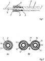
- the optical waveguide comprises an optical fiber 1 with a core and a cladding polymeric material and a tube 2 made of metal, which provides mechanical protection for the Fiber 1 and an electrical conductor forms the wall of the tube 2 is radial Stiffening and improvement of flexibility curled, the curl in the form of a Helix 3 runs around the axis 4 of the optical waveguide.
- the tube 2 On the outside is the tube 2 provided with insulation 5, such as a layer of polyethylene. It prevents Short circuits between the tube 2 and a support part, such as the body part Vehicle on which it is installed
- the tube 2 is connected to an end piece 6, for example is crimped or screwed to the helical corrugation also made of metal and used for mechanical fixing and electrical Contacting the tube 2.
- a central opening 7 allows the fiber 1 to Lead connection to other components out of pipe 2. This prevents one Protective cover 8 made of an opaque polymer that damage the fiber 1st or there is an incidence of light in this area. Also inside the tube 2 is one Protective cover 8 is useful to avoid abrasion of the fiber 1.
- An overmolding 9 shown in broken lines connects the end piece 6 Moisture-proof with the insulation 5. It is also possible to use elements in this way a connector, such as projections for guiding or locking.
- FIG. 2a shows a cross section through the optical waveguide in FIG. 1 central fiber 1 with its protective cover 8, the tube 2 and the outer insulation 5.
- Fig. 2b shows the cross section through a hybrid cable with two optical fibers the optical fibers 10, 11. They are each in a protective cover 12, 13 and are arranged in metal tubes 14, 15. Both tubes 14, 15 are from one common insulation 16 enclosed. A constriction 17 with a notch 18 enables the simple separation of both optical fibers.
- a connected electro-optical component different Supply voltages via the two mutually insulated pipes 14, 15 are supplied become. This allows the two fibers 10, 11, two independent of each other Provide systems for optical data transmission, for example to ensure security increase.
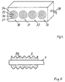
- Fig. 3 cross sections through hybrid cables with several electrical conductors are shown.
- the cables in drawing files (a) and (b) have a diameter of for example 3-4 mm each from a polymeric optical fiber 20, in a smooth inner tube 21, which is guided coaxially in an outer corrugated tube 22, both tubes 21, 22nd are made of metal and serve as electrical conductors through an intermediate one arranged foamed or compact insulation 23 are spaced apart.
- the tube 22 is also provided with insulation 24.
- the inner tube 21 can be an open one Have longitudinal gap 25. Thus, it can be easily formed by mechanical shaping Manufacture way from a metal strip without the need to To close longitudinal gap 25, for example by welding. By using two However, the protection of the fiber 20 can be carried out all round closed tubes 21, 22 improve.
- 3c shows an embodiment of the hybrid cable with two corrugated metal tubes 21, 22. In this way there is good flexibility even with larger diameters of the cable reachable.
- the outer corrugated tube 26 is preferably located on the electrical potential of the body of a vehicle or the frame of a Device and serves as a return line. In this case, an outer jacket 27 be dispensed with, while such a jacket 27 is in danger of corrosion or deviating potential of the corrugated tube 26 proves to be expedient.
- the optical waveguides according to the invention with a star coupler are preferred connected, as shown in Figure 4.
- the coupler comprises several, four in the example Connections 30-33, each of which can be connected to an optical waveguide according to the invention are.
- an optical coupling element 34 for example one Lens, which enables the coupling and decoupling of light into the fiber 1
- the coupling elements 34 of all connections are interconnected by an optical one Star coupler, preferably connected to an optical gain medium.
- the coupling element 34 is concentric with three electrical contacts 35-37 surround.
- the inner contact 35 serves to connect an electrical one Conductor with a first supply voltage (e.g. 12 V), the contact 35 for connection a second electrical conductor with a second supply voltage (e.g. 42 V) and the contact 37 as a ground contact.
- Similar contacts 35 - 37 of all connections 30 - 33 are electrically connected to each other.
- the contacts 35 - 37 are useful to the contacts 35 - 37 as Form plug contacts, in which, for example, the end piece of a Optical fiber can be inserted
- the contacts 35 - 37 as Threads are formed, in which there is an end piece or a spiral corrugated can screw in the electrical conductor of an optical fiber Coupler the connection for all electrical conductors of the optical fibers to the Power supply, which takes place via an electrical supply line 38 of the coupler.
- FIG. 5 shows a further exemplary embodiment of an optical waveguide according to the teaching of Invention shown.
- the foam layer 39 consists of Polyethylene, polypropylene or other temperature-resistant plastic.
- the degree of frothing should survey over 50%, preferably up to 85%.
- the wall thickness of the Foam layer 39 is preferably 0.3 to 2.0 mm.
- the main advantage of Foam layer can be seen in the fact that it has succeeded in the optical waveguide Use ambient temperatures up to 130 ° C.
- the foam layer forms moreover a cushion for the fiber. For this it is advantageous if the foam has a soft mechanical characteristic that does not contribute to an increase in damping the fiber leads. It ensures that mechanical forces are neither radial nor axial Act in the direction of the fiber.
- the production is advantageously carried out by extrusion of a foamable Plastic layer on the fiber, the foaming process chemically or physically is carried out.
- a metal band is inserted lengthwise around the of the foam layer 39 provided fiber 1 to a tube with a longitudinal slot shaped.
- the tube can be reduced to a small one Diameter can be pulled down and is then used in the same operation an annular or helical corrugation.
- one can Plastic jacket to be extruded onto the corrugated pipe.
Applications Claiming Priority (4)
| Application Number | Priority Date | Filing Date | Title |
|---|---|---|---|
| DE19852480 | 1998-11-13 | ||
| DE1998152480 DE19852480A1 (de) | 1998-11-13 | 1998-11-13 | Lichtwellenleiter mit Schutzrohr |
| DE19901354 | 1999-01-15 | ||
| DE1999101354 DE19901354A1 (de) | 1999-01-15 | 1999-01-15 | Lichtwellenleiter mit Schutzrohr |
Publications (1)
| Publication Number | Publication Date |
|---|---|
| EP1001294A1 true EP1001294A1 (fr) | 2000-05-17 |
Family
ID=26050137
Family Applications (1)
| Application Number | Title | Priority Date | Filing Date |
|---|---|---|---|
| EP99402493A Ceased EP1001294A1 (fr) | 1998-11-13 | 1999-10-11 | Guide d'onde optique avec tube de protection |
Country Status (3)
| Country | Link |
|---|---|
| US (1) | US6246821B1 (fr) |
| EP (1) | EP1001294A1 (fr) |
| JP (1) | JP2000147337A (fr) |
Cited By (1)
| Publication number | Priority date | Publication date | Assignee | Title |
|---|---|---|---|---|
| DE102014210992A1 (de) * | 2014-06-10 | 2015-12-17 | Conti Temic Microelectronic Gmbh | Sensorsystem |
Families Citing this family (174)
| Publication number | Priority date | Publication date | Assignee | Title |
|---|---|---|---|---|
| JP2002199388A (ja) * | 2000-12-25 | 2002-07-12 | Canon Inc | X線画像撮影装置 |
| US6778319B2 (en) * | 2001-09-10 | 2004-08-17 | Np Photonics, Inc. | Side-pumped multi-port optical amplifier and method of manufacture using fiber drawing technologies |
| EP1468319A2 (fr) * | 2002-01-23 | 2004-10-20 | Tyco Electronics Raychem N.V. | Scellement de tube de fibre optique |
| US7352937B2 (en) * | 2002-12-17 | 2008-04-01 | Finisar Corporation | Devices, systems and methods for connecting a single mode fiber to a legacy multi-mode fiber |
| US7425676B2 (en) * | 2005-09-08 | 2008-09-16 | At&T Intellectual Property L.L.P. | Coaxial cable for exterior use |
| US7272281B2 (en) * | 2006-02-01 | 2007-09-18 | Sbc Knowledge Ventures, L.P. | Powered fiber cable |
| US7539379B2 (en) * | 2006-02-01 | 2009-05-26 | At&T Intellectual Property I, L.P. | Electronic cable signature |
| US7424189B2 (en) * | 2006-03-09 | 2008-09-09 | Adc Telecommunications, Inc. | Mid-span breakout with potted closure |
| US7609925B2 (en) * | 2007-04-12 | 2009-10-27 | Adc Telecommunications, Inc. | Fiber optic cable breakout configuration with tensile reinforcement |
| US7532799B2 (en) * | 2007-04-12 | 2009-05-12 | Adc Telecommunications | Fiber optic telecommunications cable assembly |
| PE20150295A1 (es) * | 2012-03-08 | 2015-03-04 | Weatherford Lamb | Transductor optico con via de paso integrada |
| US10009065B2 (en) | 2012-12-05 | 2018-06-26 | At&T Intellectual Property I, L.P. | Backhaul link for distributed antenna system |
| US9113347B2 (en) | 2012-12-05 | 2015-08-18 | At&T Intellectual Property I, Lp | Backhaul link for distributed antenna system |
| US9525524B2 (en) | 2013-05-31 | 2016-12-20 | At&T Intellectual Property I, L.P. | Remote distributed antenna system |
| US9999038B2 (en) | 2013-05-31 | 2018-06-12 | At&T Intellectual Property I, L.P. | Remote distributed antenna system |
| US8897697B1 (en) | 2013-11-06 | 2014-11-25 | At&T Intellectual Property I, Lp | Millimeter-wave surface-wave communications |
| US9209902B2 (en) | 2013-12-10 | 2015-12-08 | At&T Intellectual Property I, L.P. | Quasi-optical coupler |
| KR20150078265A (ko) * | 2013-12-30 | 2015-07-08 | 엘에스전선 주식회사 | 광전복합케이블 |
| US9692101B2 (en) | 2014-08-26 | 2017-06-27 | At&T Intellectual Property I, L.P. | Guided wave couplers for coupling electromagnetic waves between a waveguide surface and a surface of a wire |
| US9768833B2 (en) | 2014-09-15 | 2017-09-19 | At&T Intellectual Property I, L.P. | Method and apparatus for sensing a condition in a transmission medium of electromagnetic waves |
| US10063280B2 (en) | 2014-09-17 | 2018-08-28 | At&T Intellectual Property I, L.P. | Monitoring and mitigating conditions in a communication network |
| US9628854B2 (en) | 2014-09-29 | 2017-04-18 | At&T Intellectual Property I, L.P. | Method and apparatus for distributing content in a communication network |
| US9615269B2 (en) | 2014-10-02 | 2017-04-04 | At&T Intellectual Property I, L.P. | Method and apparatus that provides fault tolerance in a communication network |
| US9685992B2 (en) | 2014-10-03 | 2017-06-20 | At&T Intellectual Property I, L.P. | Circuit panel network and methods thereof |
| US9503189B2 (en) | 2014-10-10 | 2016-11-22 | At&T Intellectual Property I, L.P. | Method and apparatus for arranging communication sessions in a communication system |
| US9762289B2 (en) | 2014-10-14 | 2017-09-12 | At&T Intellectual Property I, L.P. | Method and apparatus for transmitting or receiving signals in a transportation system |
| US9973299B2 (en) | 2014-10-14 | 2018-05-15 | At&T Intellectual Property I, L.P. | Method and apparatus for adjusting a mode of communication in a communication network |
| US9577306B2 (en) | 2014-10-21 | 2017-02-21 | At&T Intellectual Property I, L.P. | Guided-wave transmission device and methods for use therewith |
| US9564947B2 (en) | 2014-10-21 | 2017-02-07 | At&T Intellectual Property I, L.P. | Guided-wave transmission device with diversity and methods for use therewith |
| US9769020B2 (en) | 2014-10-21 | 2017-09-19 | At&T Intellectual Property I, L.P. | Method and apparatus for responding to events affecting communications in a communication network |
| US9780834B2 (en) | 2014-10-21 | 2017-10-03 | At&T Intellectual Property I, L.P. | Method and apparatus for transmitting electromagnetic waves |
| US9312919B1 (en) | 2014-10-21 | 2016-04-12 | At&T Intellectual Property I, Lp | Transmission device with impairment compensation and methods for use therewith |
| US9653770B2 (en) | 2014-10-21 | 2017-05-16 | At&T Intellectual Property I, L.P. | Guided wave coupler, coupling module and methods for use therewith |
| US9520945B2 (en) | 2014-10-21 | 2016-12-13 | At&T Intellectual Property I, L.P. | Apparatus for providing communication services and methods thereof |
| US9627768B2 (en) | 2014-10-21 | 2017-04-18 | At&T Intellectual Property I, L.P. | Guided-wave transmission device with non-fundamental mode propagation and methods for use therewith |
| US9654173B2 (en) | 2014-11-20 | 2017-05-16 | At&T Intellectual Property I, L.P. | Apparatus for powering a communication device and methods thereof |
| US10009067B2 (en) | 2014-12-04 | 2018-06-26 | At&T Intellectual Property I, L.P. | Method and apparatus for configuring a communication interface |
| US9680670B2 (en) | 2014-11-20 | 2017-06-13 | At&T Intellectual Property I, L.P. | Transmission device with channel equalization and control and methods for use therewith |
| US9954287B2 (en) | 2014-11-20 | 2018-04-24 | At&T Intellectual Property I, L.P. | Apparatus for converting wireless signals and electromagnetic waves and methods thereof |
| US9800327B2 (en) | 2014-11-20 | 2017-10-24 | At&T Intellectual Property I, L.P. | Apparatus for controlling operations of a communication device and methods thereof |
| US9997819B2 (en) | 2015-06-09 | 2018-06-12 | At&T Intellectual Property I, L.P. | Transmission medium and method for facilitating propagation of electromagnetic waves via a core |
| US10243784B2 (en) | 2014-11-20 | 2019-03-26 | At&T Intellectual Property I, L.P. | System for generating topology information and methods thereof |
| US9544006B2 (en) | 2014-11-20 | 2017-01-10 | At&T Intellectual Property I, L.P. | Transmission device with mode division multiplexing and methods for use therewith |
| US9461706B1 (en) | 2015-07-31 | 2016-10-04 | At&T Intellectual Property I, Lp | Method and apparatus for exchanging communication signals |
| US10340573B2 (en) | 2016-10-26 | 2019-07-02 | At&T Intellectual Property I, L.P. | Launcher with cylindrical coupling device and methods for use therewith |
| US9742462B2 (en) | 2014-12-04 | 2017-08-22 | At&T Intellectual Property I, L.P. | Transmission medium and communication interfaces and methods for use therewith |
| US10144036B2 (en) | 2015-01-30 | 2018-12-04 | At&T Intellectual Property I, L.P. | Method and apparatus for mitigating interference affecting a propagation of electromagnetic waves guided by a transmission medium |
| US9876570B2 (en) | 2015-02-20 | 2018-01-23 | At&T Intellectual Property I, Lp | Guided-wave transmission device with non-fundamental mode propagation and methods for use therewith |
| US9749013B2 (en) | 2015-03-17 | 2017-08-29 | At&T Intellectual Property I, L.P. | Method and apparatus for reducing attenuation of electromagnetic waves guided by a transmission medium |
| US9705561B2 (en) | 2015-04-24 | 2017-07-11 | At&T Intellectual Property I, L.P. | Directional coupling device and methods for use therewith |
| US10224981B2 (en) | 2015-04-24 | 2019-03-05 | At&T Intellectual Property I, Lp | Passive electrical coupling device and methods for use therewith |
| US9948354B2 (en) | 2015-04-28 | 2018-04-17 | At&T Intellectual Property I, L.P. | Magnetic coupling device with reflective plate and methods for use therewith |
| US9793954B2 (en) | 2015-04-28 | 2017-10-17 | At&T Intellectual Property I, L.P. | Magnetic coupling device and methods for use therewith |
| US9871282B2 (en) | 2015-05-14 | 2018-01-16 | At&T Intellectual Property I, L.P. | At least one transmission medium having a dielectric surface that is covered at least in part by a second dielectric |
| US9748626B2 (en) | 2015-05-14 | 2017-08-29 | At&T Intellectual Property I, L.P. | Plurality of cables having different cross-sectional shapes which are bundled together to form a transmission medium |
| US9490869B1 (en) | 2015-05-14 | 2016-11-08 | At&T Intellectual Property I, L.P. | Transmission medium having multiple cores and methods for use therewith |
| US10650940B2 (en) | 2015-05-15 | 2020-05-12 | At&T Intellectual Property I, L.P. | Transmission medium having a conductive material and methods for use therewith |
| US10679767B2 (en) | 2015-05-15 | 2020-06-09 | At&T Intellectual Property I, L.P. | Transmission medium having a conductive material and methods for use therewith |
| US9917341B2 (en) | 2015-05-27 | 2018-03-13 | At&T Intellectual Property I, L.P. | Apparatus and method for launching electromagnetic waves and for modifying radial dimensions of the propagating electromagnetic waves |
| US10103801B2 (en) | 2015-06-03 | 2018-10-16 | At&T Intellectual Property I, L.P. | Host node device and methods for use therewith |
| US9912381B2 (en) | 2015-06-03 | 2018-03-06 | At&T Intellectual Property I, Lp | Network termination and methods for use therewith |
| US10812174B2 (en) | 2015-06-03 | 2020-10-20 | At&T Intellectual Property I, L.P. | Client node device and methods for use therewith |
| US10154493B2 (en) | 2015-06-03 | 2018-12-11 | At&T Intellectual Property I, L.P. | Network termination and methods for use therewith |
| US10348391B2 (en) | 2015-06-03 | 2019-07-09 | At&T Intellectual Property I, L.P. | Client node device with frequency conversion and methods for use therewith |
| US9866309B2 (en) | 2015-06-03 | 2018-01-09 | At&T Intellectual Property I, Lp | Host node device and methods for use therewith |
| US9913139B2 (en) | 2015-06-09 | 2018-03-06 | At&T Intellectual Property I, L.P. | Signal fingerprinting for authentication of communicating devices |
| US9608692B2 (en) | 2015-06-11 | 2017-03-28 | At&T Intellectual Property I, L.P. | Repeater and methods for use therewith |
| US10142086B2 (en) | 2015-06-11 | 2018-11-27 | At&T Intellectual Property I, L.P. | Repeater and methods for use therewith |
| US9820146B2 (en) | 2015-06-12 | 2017-11-14 | At&T Intellectual Property I, L.P. | Method and apparatus for authentication and identity management of communicating devices |
| US9667317B2 (en) | 2015-06-15 | 2017-05-30 | At&T Intellectual Property I, L.P. | Method and apparatus for providing security using network traffic adjustments |
| US9509415B1 (en) | 2015-06-25 | 2016-11-29 | At&T Intellectual Property I, L.P. | Methods and apparatus for inducing a fundamental wave mode on a transmission medium |
| US9640850B2 (en) | 2015-06-25 | 2017-05-02 | At&T Intellectual Property I, L.P. | Methods and apparatus for inducing a non-fundamental wave mode on a transmission medium |
| US9865911B2 (en) | 2015-06-25 | 2018-01-09 | At&T Intellectual Property I, L.P. | Waveguide system for slot radiating first electromagnetic waves that are combined into a non-fundamental wave mode second electromagnetic wave on a transmission medium |
| US10205655B2 (en) | 2015-07-14 | 2019-02-12 | At&T Intellectual Property I, L.P. | Apparatus and methods for communicating utilizing an antenna array and multiple communication paths |
| US10033108B2 (en) | 2015-07-14 | 2018-07-24 | At&T Intellectual Property I, L.P. | Apparatus and methods for generating an electromagnetic wave having a wave mode that mitigates interference |
| US9853342B2 (en) | 2015-07-14 | 2017-12-26 | At&T Intellectual Property I, L.P. | Dielectric transmission medium connector and methods for use therewith |
| US9847566B2 (en) | 2015-07-14 | 2017-12-19 | At&T Intellectual Property I, L.P. | Method and apparatus for adjusting a field of a signal to mitigate interference |
| US10320586B2 (en) | 2015-07-14 | 2019-06-11 | At&T Intellectual Property I, L.P. | Apparatus and methods for generating non-interfering electromagnetic waves on an insulated transmission medium |
| US9836957B2 (en) | 2015-07-14 | 2017-12-05 | At&T Intellectual Property I, L.P. | Method and apparatus for communicating with premises equipment |
| US10170840B2 (en) | 2015-07-14 | 2019-01-01 | At&T Intellectual Property I, L.P. | Apparatus and methods for sending or receiving electromagnetic signals |
| US10033107B2 (en) | 2015-07-14 | 2018-07-24 | At&T Intellectual Property I, L.P. | Method and apparatus for coupling an antenna to a device |
| US9882257B2 (en) | 2015-07-14 | 2018-01-30 | At&T Intellectual Property I, L.P. | Method and apparatus for launching a wave mode that mitigates interference |
| US9722318B2 (en) | 2015-07-14 | 2017-08-01 | At&T Intellectual Property I, L.P. | Method and apparatus for coupling an antenna to a device |
| US9628116B2 (en) | 2015-07-14 | 2017-04-18 | At&T Intellectual Property I, L.P. | Apparatus and methods for transmitting wireless signals |
| US10148016B2 (en) | 2015-07-14 | 2018-12-04 | At&T Intellectual Property I, L.P. | Apparatus and methods for communicating utilizing an antenna array |
| US10044409B2 (en) | 2015-07-14 | 2018-08-07 | At&T Intellectual Property I, L.P. | Transmission medium and methods for use therewith |
| US10341142B2 (en) | 2015-07-14 | 2019-07-02 | At&T Intellectual Property I, L.P. | Apparatus and methods for generating non-interfering electromagnetic waves on an uninsulated conductor |
| US9793951B2 (en) | 2015-07-15 | 2017-10-17 | At&T Intellectual Property I, L.P. | Method and apparatus for launching a wave mode that mitigates interference |
| US9608740B2 (en) | 2015-07-15 | 2017-03-28 | At&T Intellectual Property I, L.P. | Method and apparatus for launching a wave mode that mitigates interference |
| US10090606B2 (en) | 2015-07-15 | 2018-10-02 | At&T Intellectual Property I, L.P. | Antenna system with dielectric array and methods for use therewith |
| US10784670B2 (en) | 2015-07-23 | 2020-09-22 | At&T Intellectual Property I, L.P. | Antenna support for aligning an antenna |
| US9948333B2 (en) | 2015-07-23 | 2018-04-17 | At&T Intellectual Property I, L.P. | Method and apparatus for wireless communications to mitigate interference |
| US9912027B2 (en) | 2015-07-23 | 2018-03-06 | At&T Intellectual Property I, L.P. | Method and apparatus for exchanging communication signals |
| US9749053B2 (en) | 2015-07-23 | 2017-08-29 | At&T Intellectual Property I, L.P. | Node device, repeater and methods for use therewith |
| US9871283B2 (en) | 2015-07-23 | 2018-01-16 | At&T Intellectual Property I, Lp | Transmission medium having a dielectric core comprised of plural members connected by a ball and socket configuration |
| US10020587B2 (en) | 2015-07-31 | 2018-07-10 | At&T Intellectual Property I, L.P. | Radial antenna and methods for use therewith |
| US9967173B2 (en) | 2015-07-31 | 2018-05-08 | At&T Intellectual Property I, L.P. | Method and apparatus for authentication and identity management of communicating devices |
| US9735833B2 (en) | 2015-07-31 | 2017-08-15 | At&T Intellectual Property I, L.P. | Method and apparatus for communications management in a neighborhood network |
| US9904535B2 (en) | 2015-09-14 | 2018-02-27 | At&T Intellectual Property I, L.P. | Method and apparatus for distributing software |
| US10051629B2 (en) | 2015-09-16 | 2018-08-14 | At&T Intellectual Property I, L.P. | Method and apparatus for use with a radio distributed antenna system having an in-band reference signal |
| US10136434B2 (en) | 2015-09-16 | 2018-11-20 | At&T Intellectual Property I, L.P. | Method and apparatus for use with a radio distributed antenna system having an ultra-wideband control channel |
| US9705571B2 (en) | 2015-09-16 | 2017-07-11 | At&T Intellectual Property I, L.P. | Method and apparatus for use with a radio distributed antenna system |
| US10009901B2 (en) | 2015-09-16 | 2018-06-26 | At&T Intellectual Property I, L.P. | Method, apparatus, and computer-readable storage medium for managing utilization of wireless resources between base stations |
| US10009063B2 (en) | 2015-09-16 | 2018-06-26 | At&T Intellectual Property I, L.P. | Method and apparatus for use with a radio distributed antenna system having an out-of-band reference signal |
| US10079661B2 (en) | 2015-09-16 | 2018-09-18 | At&T Intellectual Property I, L.P. | Method and apparatus for use with a radio distributed antenna system having a clock reference |
| US9769128B2 (en) | 2015-09-28 | 2017-09-19 | At&T Intellectual Property I, L.P. | Method and apparatus for encryption of communications over a network |
| US9729197B2 (en) | 2015-10-01 | 2017-08-08 | At&T Intellectual Property I, L.P. | Method and apparatus for communicating network management traffic over a network |
| US9882277B2 (en) | 2015-10-02 | 2018-01-30 | At&T Intellectual Property I, Lp | Communication device and antenna assembly with actuated gimbal mount |
| US9876264B2 (en) | 2015-10-02 | 2018-01-23 | At&T Intellectual Property I, Lp | Communication system, guided wave switch and methods for use therewith |
| US10074890B2 (en) | 2015-10-02 | 2018-09-11 | At&T Intellectual Property I, L.P. | Communication device and antenna with integrated light assembly |
| US10051483B2 (en) | 2015-10-16 | 2018-08-14 | At&T Intellectual Property I, L.P. | Method and apparatus for directing wireless signals |
| US10355367B2 (en) | 2015-10-16 | 2019-07-16 | At&T Intellectual Property I, L.P. | Antenna structure for exchanging wireless signals |
| US10665942B2 (en) | 2015-10-16 | 2020-05-26 | At&T Intellectual Property I, L.P. | Method and apparatus for adjusting wireless communications |
| US9912419B1 (en) | 2016-08-24 | 2018-03-06 | At&T Intellectual Property I, L.P. | Method and apparatus for managing a fault in a distributed antenna system |
| US9860075B1 (en) | 2016-08-26 | 2018-01-02 | At&T Intellectual Property I, L.P. | Method and communication node for broadband distribution |
| US10291311B2 (en) | 2016-09-09 | 2019-05-14 | At&T Intellectual Property I, L.P. | Method and apparatus for mitigating a fault in a distributed antenna system |
| US11032819B2 (en) | 2016-09-15 | 2021-06-08 | At&T Intellectual Property I, L.P. | Method and apparatus for use with a radio distributed antenna system having a control channel reference signal |
| US10340600B2 (en) | 2016-10-18 | 2019-07-02 | At&T Intellectual Property I, L.P. | Apparatus and methods for launching guided waves via plural waveguide systems |
| US10135147B2 (en) | 2016-10-18 | 2018-11-20 | At&T Intellectual Property I, L.P. | Apparatus and methods for launching guided waves via an antenna |
| US10135146B2 (en) | 2016-10-18 | 2018-11-20 | At&T Intellectual Property I, L.P. | Apparatus and methods for launching guided waves via circuits |
| US9876605B1 (en) | 2016-10-21 | 2018-01-23 | At&T Intellectual Property I, L.P. | Launcher and coupling system to support desired guided wave mode |
| US10811767B2 (en) | 2016-10-21 | 2020-10-20 | At&T Intellectual Property I, L.P. | System and dielectric antenna with convex dielectric radome |
| US9991580B2 (en) | 2016-10-21 | 2018-06-05 | At&T Intellectual Property I, L.P. | Launcher and coupling system for guided wave mode cancellation |
| US10374316B2 (en) | 2016-10-21 | 2019-08-06 | At&T Intellectual Property I, L.P. | System and dielectric antenna with non-uniform dielectric |
| US10312567B2 (en) | 2016-10-26 | 2019-06-04 | At&T Intellectual Property I, L.P. | Launcher with planar strip antenna and methods for use therewith |
| US10224634B2 (en) | 2016-11-03 | 2019-03-05 | At&T Intellectual Property I, L.P. | Methods and apparatus for adjusting an operational characteristic of an antenna |
| US10498044B2 (en) | 2016-11-03 | 2019-12-03 | At&T Intellectual Property I, L.P. | Apparatus for configuring a surface of an antenna |
| US10225025B2 (en) | 2016-11-03 | 2019-03-05 | At&T Intellectual Property I, L.P. | Method and apparatus for detecting a fault in a communication system |
| US10291334B2 (en) | 2016-11-03 | 2019-05-14 | At&T Intellectual Property I, L.P. | System for detecting a fault in a communication system |
| US10340601B2 (en) | 2016-11-23 | 2019-07-02 | At&T Intellectual Property I, L.P. | Multi-antenna system and methods for use therewith |
| US10340603B2 (en) | 2016-11-23 | 2019-07-02 | At&T Intellectual Property I, L.P. | Antenna system having shielded structural configurations for assembly |
| US10178445B2 (en) | 2016-11-23 | 2019-01-08 | At&T Intellectual Property I, L.P. | Methods, devices, and systems for load balancing between a plurality of waveguides |
| US10090594B2 (en) | 2016-11-23 | 2018-10-02 | At&T Intellectual Property I, L.P. | Antenna system having structural configurations for assembly |
| US10535928B2 (en) | 2016-11-23 | 2020-01-14 | At&T Intellectual Property I, L.P. | Antenna system and methods for use therewith |
| US10305190B2 (en) | 2016-12-01 | 2019-05-28 | At&T Intellectual Property I, L.P. | Reflecting dielectric antenna system and methods for use therewith |
| US10361489B2 (en) | 2016-12-01 | 2019-07-23 | At&T Intellectual Property I, L.P. | Dielectric dish antenna system and methods for use therewith |
| US10020844B2 (en) | 2016-12-06 | 2018-07-10 | T&T Intellectual Property I, L.P. | Method and apparatus for broadcast communication via guided waves |
| US10135145B2 (en) | 2016-12-06 | 2018-11-20 | At&T Intellectual Property I, L.P. | Apparatus and methods for generating an electromagnetic wave along a transmission medium |
| US10819035B2 (en) | 2016-12-06 | 2020-10-27 | At&T Intellectual Property I, L.P. | Launcher with helical antenna and methods for use therewith |
| US10694379B2 (en) | 2016-12-06 | 2020-06-23 | At&T Intellectual Property I, L.P. | Waveguide system with device-based authentication and methods for use therewith |
| US10326494B2 (en) | 2016-12-06 | 2019-06-18 | At&T Intellectual Property I, L.P. | Apparatus for measurement de-embedding and methods for use therewith |
| US10382976B2 (en) | 2016-12-06 | 2019-08-13 | At&T Intellectual Property I, L.P. | Method and apparatus for managing wireless communications based on communication paths and network device positions |
| US10727599B2 (en) | 2016-12-06 | 2020-07-28 | At&T Intellectual Property I, L.P. | Launcher with slot antenna and methods for use therewith |
| US9927517B1 (en) | 2016-12-06 | 2018-03-27 | At&T Intellectual Property I, L.P. | Apparatus and methods for sensing rainfall |
| US10755542B2 (en) | 2016-12-06 | 2020-08-25 | At&T Intellectual Property I, L.P. | Method and apparatus for surveillance via guided wave communication |
| US10637149B2 (en) | 2016-12-06 | 2020-04-28 | At&T Intellectual Property I, L.P. | Injection molded dielectric antenna and methods for use therewith |
| US10439675B2 (en) | 2016-12-06 | 2019-10-08 | At&T Intellectual Property I, L.P. | Method and apparatus for repeating guided wave communication signals |
| US10168695B2 (en) | 2016-12-07 | 2019-01-01 | At&T Intellectual Property I, L.P. | Method and apparatus for controlling an unmanned aircraft |
| US10243270B2 (en) | 2016-12-07 | 2019-03-26 | At&T Intellectual Property I, L.P. | Beam adaptive multi-feed dielectric antenna system and methods for use therewith |
| US10389029B2 (en) | 2016-12-07 | 2019-08-20 | At&T Intellectual Property I, L.P. | Multi-feed dielectric antenna system with core selection and methods for use therewith |
| US10139820B2 (en) | 2016-12-07 | 2018-11-27 | At&T Intellectual Property I, L.P. | Method and apparatus for deploying equipment of a communication system |
| US10547348B2 (en) | 2016-12-07 | 2020-01-28 | At&T Intellectual Property I, L.P. | Method and apparatus for switching transmission mediums in a communication system |
| US10027397B2 (en) | 2016-12-07 | 2018-07-17 | At&T Intellectual Property I, L.P. | Distributed antenna system and methods for use therewith |
| US10446936B2 (en) | 2016-12-07 | 2019-10-15 | At&T Intellectual Property I, L.P. | Multi-feed dielectric antenna system and methods for use therewith |
| US10359749B2 (en) | 2016-12-07 | 2019-07-23 | At&T Intellectual Property I, L.P. | Method and apparatus for utilities management via guided wave communication |
| US9893795B1 (en) | 2016-12-07 | 2018-02-13 | At&T Intellectual Property I, Lp | Method and repeater for broadband distribution |
| US10326689B2 (en) | 2016-12-08 | 2019-06-18 | At&T Intellectual Property I, L.P. | Method and system for providing alternative communication paths |
| US9911020B1 (en) | 2016-12-08 | 2018-03-06 | At&T Intellectual Property I, L.P. | Method and apparatus for tracking via a radio frequency identification device |
| US9998870B1 (en) | 2016-12-08 | 2018-06-12 | At&T Intellectual Property I, L.P. | Method and apparatus for proximity sensing |
| US10389037B2 (en) | 2016-12-08 | 2019-08-20 | At&T Intellectual Property I, L.P. | Apparatus and methods for selecting sections of an antenna array and use therewith |
| US10069535B2 (en) | 2016-12-08 | 2018-09-04 | At&T Intellectual Property I, L.P. | Apparatus and methods for launching electromagnetic waves having a certain electric field structure |
| US10938108B2 (en) | 2016-12-08 | 2021-03-02 | At&T Intellectual Property I, L.P. | Frequency selective multi-feed dielectric antenna system and methods for use therewith |
| US10530505B2 (en) | 2016-12-08 | 2020-01-07 | At&T Intellectual Property I, L.P. | Apparatus and methods for launching electromagnetic waves along a transmission medium |
| US10411356B2 (en) | 2016-12-08 | 2019-09-10 | At&T Intellectual Property I, L.P. | Apparatus and methods for selectively targeting communication devices with an antenna array |
| US10103422B2 (en) | 2016-12-08 | 2018-10-16 | At&T Intellectual Property I, L.P. | Method and apparatus for mounting network devices |
| US10777873B2 (en) | 2016-12-08 | 2020-09-15 | At&T Intellectual Property I, L.P. | Method and apparatus for mounting network devices |
| US10601494B2 (en) | 2016-12-08 | 2020-03-24 | At&T Intellectual Property I, L.P. | Dual-band communication device and method for use therewith |
| US10916969B2 (en) | 2016-12-08 | 2021-02-09 | At&T Intellectual Property I, L.P. | Method and apparatus for providing power using an inductive coupling |
| US10340983B2 (en) | 2016-12-09 | 2019-07-02 | At&T Intellectual Property I, L.P. | Method and apparatus for surveying remote sites via guided wave communications |
| US9838896B1 (en) | 2016-12-09 | 2017-12-05 | At&T Intellectual Property I, L.P. | Method and apparatus for assessing network coverage |
| US10264586B2 (en) | 2016-12-09 | 2019-04-16 | At&T Mobility Ii Llc | Cloud-based packet controller and methods for use therewith |
| US9973940B1 (en) | 2017-02-27 | 2018-05-15 | At&T Intellectual Property I, L.P. | Apparatus and methods for dynamic impedance matching of a guided wave launcher |
| US10298293B2 (en) | 2017-03-13 | 2019-05-21 | At&T Intellectual Property I, L.P. | Apparatus of communication utilizing wireless network devices |
| RU2700038C2 (ru) * | 2018-02-14 | 2019-09-12 | Александр Петрович Демченко | Акустический волновод |
Citations (3)
| Publication number | Priority date | Publication date | Assignee | Title |
|---|---|---|---|---|
| US3357423A (en) * | 1965-03-26 | 1967-12-12 | Iota Cam Corp | Surgical light pipe and the like |
| US3955878A (en) * | 1975-02-13 | 1976-05-11 | International Telephone And Telegraph Corporation | Fiber optic transmission line |
| DE2743260A1 (de) * | 1977-09-26 | 1979-04-05 | Kabel Metallwerke Ghh | Nachrichtenkabel mit lichtwellenleitern und verfahren zu seiner herstellung |
Family Cites Families (3)
| Publication number | Priority date | Publication date | Assignee | Title |
|---|---|---|---|---|
| US4435238A (en) * | 1982-10-28 | 1984-03-06 | International Telephone And Telegraph Corporation | Manufacturing process for a low loss optical fiber cable |
| US5001303A (en) * | 1989-05-26 | 1991-03-19 | Coleman Cable Systems, Inc. | Metallic sheath electrical cable |
| US5261021A (en) * | 1992-04-10 | 1993-11-09 | Nordson Corporation | Apparatus and method for forming cable |
-
1999
- 1999-10-11 EP EP99402493A patent/EP1001294A1/fr not_active Ceased
- 1999-11-12 JP JP11322070A patent/JP2000147337A/ja not_active Withdrawn
- 1999-11-12 US US09/438,834 patent/US6246821B1/en not_active Expired - Fee Related
Patent Citations (3)
| Publication number | Priority date | Publication date | Assignee | Title |
|---|---|---|---|---|
| US3357423A (en) * | 1965-03-26 | 1967-12-12 | Iota Cam Corp | Surgical light pipe and the like |
| US3955878A (en) * | 1975-02-13 | 1976-05-11 | International Telephone And Telegraph Corporation | Fiber optic transmission line |
| DE2743260A1 (de) * | 1977-09-26 | 1979-04-05 | Kabel Metallwerke Ghh | Nachrichtenkabel mit lichtwellenleitern und verfahren zu seiner herstellung |
Cited By (1)
| Publication number | Priority date | Publication date | Assignee | Title |
|---|---|---|---|---|
| DE102014210992A1 (de) * | 2014-06-10 | 2015-12-17 | Conti Temic Microelectronic Gmbh | Sensorsystem |
Also Published As
| Publication number | Publication date |
|---|---|
| US6246821B1 (en) | 2001-06-12 |
| JP2000147337A (ja) | 2000-05-26 |
Similar Documents
| Publication | Publication Date | Title |
|---|---|---|
| EP1001294A1 (fr) | Guide d'onde optique avec tube de protection | |
| EP0620565B1 (fr) | Câble coaxial à haute fréquence | |
| EP2662866B1 (fr) | Câble électrique conducteur plat multicouches | |
| DE3023398C2 (fr) | ||
| DE2851955C2 (fr) | ||
| DE69921539T2 (de) | Geschlitztes Kompositkabel mit einem Kabelprofil mit einer rohrförmiger Öffnung für Kupferpaare und ein Schlitz für einen optischen Faser | |
| DE10115423A1 (de) | Kombiniertes Mikro-Lichtwellenleiterkabel/Elektrokabel | |
| DE19641616B4 (de) | Nachrichtenkabel mit im Bereich des Außenmantels angebrachten Zugentlastungselementen | |
| EP0236800A2 (fr) | Câble de communication avec des guides d'ondes lumineuses | |
| DE3031833A1 (de) | Strangfoermiges verbindungselement aus kunststoff fuer kabel u.ae. | |
| WO2002086914A2 (fr) | Systeme a plusieurs conducteurs pour la transmission d'energie et/ou de donnees | |
| DE3538664C2 (fr) | ||
| WO2021083565A1 (fr) | Dispositif de surveillance de température de segment de ligne de transmission d'énergie d'une source d'énergie à un puits d'énergie | |
| EP0324054A2 (fr) | Procédé de fabrication d'un câble optique | |
| EP0945876A1 (fr) | Cable composite avec conducteurs à fibre optique et électrique | |
| DE19901354A1 (de) | Lichtwellenleiter mit Schutzrohr | |
| EP1818221B1 (fr) | Faisceau de conducteurs | |
| DE19852480A1 (de) | Lichtwellenleiter mit Schutzrohr | |
| DE19728286C1 (de) | Verkabelungselement | |
| DE3725124A1 (de) | Verfahren zum wasser- bzw. wasserdampfdichten umkleiden von leiterverbindungen | |
| EP2875987A1 (fr) | Fil électrique et machine électrique | |
| DE3137956C2 (fr) | ||
| DE2824571A1 (de) | Rundhohlleiter | |
| EP0330278B1 (fr) | Câble optique sous marin | |
| WO2000013940A1 (fr) | Element de cablage |
Legal Events
| Date | Code | Title | Description |
|---|---|---|---|
| PUAI | Public reference made under article 153(3) epc to a published international application that has entered the european phase |
Free format text: ORIGINAL CODE: 0009012 |
|
| AK | Designated contracting states |
Kind code of ref document: A1 Designated state(s): DE FR GB IT |
|
| AX | Request for extension of the european patent |
Free format text: AL;LT;LV;MK;RO;SI |
|
| 17P | Request for examination filed |
Effective date: 20000323 |
|
| AKX | Designation fees paid |
Free format text: DE FR GB IT |
|
| RAP1 | Party data changed (applicant data changed or rights of an application transferred) |
Owner name: NEXANS |
|
| STAA | Information on the status of an ep patent application or granted ep patent |
Free format text: STATUS: THE APPLICATION HAS BEEN REFUSED |
|
| 18R | Application refused |
Effective date: 20060417 |