EP1001107A1 - Roof drain assembly - Google Patents
Roof drain assembly Download PDFInfo
- Publication number
- EP1001107A1 EP1001107A1 EP99116623A EP99116623A EP1001107A1 EP 1001107 A1 EP1001107 A1 EP 1001107A1 EP 99116623 A EP99116623 A EP 99116623A EP 99116623 A EP99116623 A EP 99116623A EP 1001107 A1 EP1001107 A1 EP 1001107A1
- Authority
- EP
- European Patent Office
- Prior art keywords
- water
- inner tube
- water drainage
- drainage system
- tube
- Prior art date
- Legal status (The legal status is an assumption and is not a legal conclusion. Google has not performed a legal analysis and makes no representation as to the accuracy of the status listed.)
- Withdrawn
Links
Images


Classifications
-
- E—FIXED CONSTRUCTIONS
- E04—BUILDING
- E04D—ROOF COVERINGS; SKY-LIGHTS; GUTTERS; ROOF-WORKING TOOLS
- E04D13/00—Special arrangements or devices in connection with roof coverings; Protection against birds; Roof drainage; Sky-lights
- E04D13/04—Roof drainage; Drainage fittings in flat roofs, balconies or the like
- E04D13/0404—Drainage on the roof surface
- E04D13/0477—Underroof drainage layers
-
- E—FIXED CONSTRUCTIONS
- E04—BUILDING
- E04D—ROOF COVERINGS; SKY-LIGHTS; GUTTERS; ROOF-WORKING TOOLS
- E04D13/00—Special arrangements or devices in connection with roof coverings; Protection against birds; Roof drainage; Sky-lights
- E04D13/04—Roof drainage; Drainage fittings in flat roofs, balconies or the like
- E04D13/0404—Drainage on the roof surface
- E04D13/0409—Drainage outlets, e.g. gullies
- E04D2013/0427—Drainage outlets, e.g. gullies with means for controlling the flow in the outlet
Definitions
- the invention relates to a water drainage system, in particular a water drainage system for roof surfaces, and especially one such a system, which prevents rainwater, which descended on one surface, in essentially undiminished Flows out and without delay.
- the structure of the planting substrate for green roofs differs depending on the type of plants that are on the roof should be planted. There are both one and one multi-layer structures known. Usually it applies that the more demanding the number of shifts increases Plants. For example, perennials, shrubs or trees are planted are usually multi-layered Superstructures required and sufficient for the plants Providing with water is pond irrigation necessary. A layered structure for such intensive green roofing thus comprises a water reservoir from which the Plants are continuously supplied with moisture can.
- FIG. 5 shows such a layer structure for intensive greening with water accumulation.
- the figure shows a partial cross section through the layers applied to the roof in the area around a water drain pipe 1, which is arranged in a shaft 19 closed with a cover 20.
- excess water is drained from the roof into the sewage system.
- the amount of excess water is reduced compared to a green roof, because of the retention properties of the layer structure 8 applied to the roof surface 2 and the planting 7.
- water flow rates can be set that are between 0 and 70% of the water that has sunk on the roof surface.
- a water reservoir 12 is provided in the layer structure 8.
- a water-guiding profile is arranged within the layer structure 8, which drains the layer structure in the vertical direction and favors the flow of water in the roof plane.
- a root protection sheet 13 and a protective layer 14 are present between the water guiding profile and the roof surface 2, which prevent the plant roots from penetrating in the direction of the roof surface and thus ensure the tightness of the roof.
- a drain layer 15 is arranged above the water guiding profile 12, which is intended to prevent water build-up in the root region of the plants 7, which can impair the growth of the plants. Separated from the drain layer 15 by a filter mat 16, there is the plant substrate 17, the actual growth substrate for the plants 7.
- the maximum water level in the water reservoir 12 of the layer structure 8 can be adjusted by the design of the water drainage system in the area of the water drainage pipe 1 specified.
- this water drain pipe is a Inserted inner pipe 4 and against the water drain pipe 1 with the help of two sealing rings 18 watertight.
- the cylindrical inner tube 4 is so in the water drain pipe 1 inserted that its upper end face in a Height above the roof surface 2, which is the desired corresponds to the maximum water level in the layer structure. If precipitation falls on the green roof, the excess water gets which is not from the upper layers of the Layer structure 8 and the plants 7 was added in the water reservoir 12. There it builds up until the given by the position of the inner tube 4 has set the maximum water level.
- the invention has for its object to provide a water drainage system that has improved water retention and largely prevents the uncontrolled outflow of water from one surface.
- the invention is intended to avoid excessive wastewater peaks occur and specified wastewater values are not adhered to can be.
- the water drainage system according to the invention is intended are particularly suitable for green roofs and ensure that despite delayed water delivery into the Sewerage does not cause permanent waterlogging, which could affect plant growth.
- the water drainage system according to the invention is also intended for suitable for use on green roofs, patios, etc. and ensure even water delivery. Damage to the surface due to frost pressure or friction an ice sheet should be avoided.
- water drainage system according to the invention to the locally found Conditions and the intended application, for example to the type of planting, flexibly adaptable, but just be set up.
- the water drainage system claimed in claim 1 relates a system which has at least one water drain pipe, through which is located on a surface Water is discharged, as well as one protruding over the surface Inner tube includes.
- Water drain pipe and inner pipe are tightly connected to each other, so that from the Surface draining water essentially exclusively reaches the water drain pipe via the inner pipe.
- the inner tube is designed so that only one predetermined, limited proportion of the water the inner tube can be introduced into the water drainage tube, per Unit of time in the inner pipe and from there into the water drain pipe can reach.
- the passage area for that Water is chosen so that only the desired amount of water per unit time drain through the inner tube can. This ensures that not immediately everything on the surface and through the inner tube derivable water is derived from the area. Much more can ensure a defined and slow water drainage be, which makes it possible, possibly predetermined To be able to comply with wastewater values.
- the water drainage system according to the invention is both suitable for areas on which water is planned and excess water then with a time delay the inner tube is drained off as soon as a certain water level is exceeded, as well as for cases without water accumulation, in those with the time delay according to the invention the water on the surface if possible to be fully derived.
- the delayed drainage of excess water can be achieved in one embodiment of the invention be that the inner tube at its over the area projecting end is open and the inner diameter of the Inner tube is chosen so that the desired flow rate per unit of time.
- water drainage system can basically like the system shown in Fig. 5 can be constructed. However becomes the inlet cross-section for the water to be drained very be much less than that of the system of the state the technique in which an instant drain of the excess Water was intended.
- the invention Inner tube, which in connection with that shown in Fig. 5 Arrangement can be used via its have a uniform inner diameter over the entire length, or it is only in a partial area on one suitable inner diameter narrowed.
- the water drainage system it is possible that in a very slow flow of water and very heavy rainfall a very high water level on the to draining area. In some cases it can however, it may be desirable to have a certain maximum water level is not exceeded. This applies, for example when there is planting on the area to be drained is present, the roots of which are due to a too high water level and waterlogging in the root area can be damaged can.
- To increase the water level above the maximum Preventing desired water levels can be in the area there is an emergency drain on the area to be drained his. Due to this emergency drain water, which after reaching the maximum desired water level towards the draining area, immediately and without time Delay dissipated from the area.
- the admission of the emergency drain is further from the height draining area away as the entrance opening (s) of the inner tube.
- the outlet of the emergency drain can, for example either into the sewage system, or the excess Water is drained from the building facade.
- the delayed Water drainage achieved in that according to the invention in the pipe jacket of the inner tube, in the area in which the inner tube protrudes beyond the surface, at least one through opening through which that is on the surface through standing water inside the inner tube and from there can drain through the water drain pipe.
- the inner tube has a plurality of through openings on.
- the number and size of the through openings are appropriate chosen so that a predetermined amount per unit of time Water can run off the surface. This can ensure be that only a limited amount of time per unit of time Water drains from the area to be drained and the specified Waste water values are complied with.
- a predetermined amount per unit of time Water can run off the surface.
- This can ensure be that only a limited amount of time per unit of time Water drains from the area to be drained and the specified Waste water values are complied with.
- several water drainage systems according to the invention can be used on one surface.
- the inner tube is expedient at its upper, closed over the surface protruding end.
- the inner tube be long that it continues beyond the drainage Area protrudes than the expected maximum water level on this area. In both cases it is prevented that water after exceeding the maximum intended Accumulation height through the upper, open end of the drain pipe a known drainage arrangement, such as was described in connection with Figure 5, uncontrolled expires.
- the water drainage system according to the invention can be used both for the drainage of areas on which the accumulation of a defined water reservoir is provided, as well as on areas from which the water is to run off completely.
- the inner tube is provided with only one or more through openings in its upper end region, while no openings are provided in the region which is adjacent to the surface to be drained.
- the area of the inner tube protruding above the surface is not provided with through openings at a height which corresponds to the maximum desired accumulation height of the water on the surface. Up to this height, water falling on the surface can be dammed up. If the water level rises above this level, the water flows through the at least one through opening into the interior of the inner pipe and from there via the water drainage pipe from the surface.
- the flow rate per time can be adjusted to the desired level for the assigned catchment area by a suitable choice of the number and size of the through openings, so that a continuous flow of the water is ensured.
- the inner tube is also in its lower area provided with through openings so that the whole on water accumulated gradually over the inner tube can drain off.
- the invention also has the advantage of the water drainage system targeted to the conditions found and To be able to adapt application areas. For example the local rainfall varies greatly and it make it seem appropriate, the flow rates accordingly adjust. This is particularly important in the case of greenery Roof areas where waterlogging is a nuisance of plant growth can result. On the other hand, it can especially in drier and less precipitation areas be expedient, descending on the green areas To keep water available for the plants longer and so to positively influence their growth. This is especially true for extensive green areas. Different too Types of layered structures for green roofs as well different types of planting make different Types of irrigation and drainage required. Occasionally can also adapt drainage to the seasonally appropriate conditions appropriate his.
- the invention enables easy adaptation of the water drainage system to the conditions described. So can the accumulation height of the water on the area to be drained can be easily adjusted by adjusting the height that area of the inner tube that of through openings should remain free, is chosen accordingly.
- the accumulation height of the water is regulated by the height, with which the inner tube protrudes over the surface.
- the speed with which accumulated on the surface Water drained from this area can, as already described by appropriate choice of the number and size of Through openings in the inner tube or the passage cross section of the inner tube can be adjusted. Corresponding this gives the period over which pent-up Water remains available on the area and for example from plants growing on this area and can be used. This can be done despite improved retention properties be prevented that water permanently dammed up because of the construction of the invention Water drainage system for a continuous Water drainage is provided when the water level is a predetermined one Height exceeds. Damage to plantings the area due to constant waterlogging can thus be avoided become.
- the necessary Precipitation values are, for example, from the regional ones Weather stations available. Order, number and Size of the through openings or the inner diameter of the Inner tube can be useful with the help of a data processing system can be calculated from known and proven systems and uses as a standard can be.
- the Type of planting the water retention properties of the area to be drained; Water loss through evaporation; the type of layer structure for green roofs and the water retention properties of this layer structure; the desired maximum discharge quantities per unit of time or where appropriate, prescribed discharge quantities per year.
- the distribution of the through openings along the inner tube does not have to be uniform according to the invention. Much more can vary the number and / or size of the through openings change in the axial direction of the inner tube. In this way a time-variable water drain can be set.
- green roof areas be at a very high water level for one initially to ensure faster water drainage. This is achieved by that number and / or size of the through openings in Increase towards the upper end of the inner tube. In this way, it can be prevented sets a high water level on the roof for a long time, damage caused by waterlogging in the root area the planting leads. However, is the water level may have dropped to a level that is no longer harmful slow drainage of water from the roof may be appropriate, around the plants with water for a long period of time to supply.
- the water drainage system is particularly preferably designed such that the position, number and / or size of the through openings can be varied variably.
- the inner pipe can be arranged displaceably in the water drain pipe. For example, if you move an inner pipe, the area of which protrudes with perforations over the area to be drained, in the longitudinal direction in the water drain pipe up or down, this changes the number of through openings through which water can flow through the inner pipe into the water drain pipe. If the inner tube is pulled further out of the water drainage pipe, more through openings are available, and the amount of water which can flow away from the surface per unit of time increases accordingly.
- the water drainage system according to the invention is equipped with a further pipe which is arranged radially inside or outside the inner pipe and bears against it.
- the inner tube and the other tube are displaceable and / or rotatable relative to one another.
- the further pipe can on the one hand be free of through-openings and then serve to set the maximum accumulation height of the water on the surface to be drained in the event of a water build-up, or it can be used to cover one or more through-openings in the inner pipe in whole or in part and thus the outflow quantity to adjust to water.
- the further tube also has one or more through openings. This is useful at least one through opening of the further tube so arranged that they are associated with an opening overlaps the inner tube.
- the scale can be constructed in this way, for example be that the position of the two pipes to each other for certain, predetermined runoff quantities. Additionally or alternatively, the scale can be a clue offer for how the position of the two Tubes to each other when used in certain layer structures, Area sizes, certain climates, certain seasons, for certain types of plantings, etc. changes.
- the described preferred embodiment of the invention Drainage system allows one and adapt the same system to a variety of applications. The system can therefore be used extremely flexibly without being complicated.
- the water drainage system is slidable in the water drainage pipe
- inner and / or other tube is in the upper End area of the inner tube and / or another tube Floating bodies available.
- This float ensures that inner tube and / or another tube according to that the prevailing water level in the area to be drained Water drain pipe can be moved up and down.
- This arrangement can help regardless of the prevailing water pressure to ensure a constant water drainage.
- the flow rate changes of water depending on how high the water supernatant is above the through openings.
- the system according to the invention expediently has a shaft into which the inner tube projects and which surrounds the inner tube at a distance from it.
- the storage space for holding the water is expediently located in the area around the end of the shaft which is adjacent to the surface to be drained. Storage space and the interior of the shaft are then connected to one another via at least one passage.
- at least one drain layer and / or a single-layer substrate and / or at least one plant substrate layer can be arranged above the storage space.
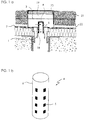
- FIG. 1a describes a water drainage system according to the invention, which is used on a gravel roof.
- the invention Water drainage system corresponds in some features the system described in connection with FIG. 5 the state of the art. To avoid repetitions, matching components should not be described again become.
- the same reference numerals are used in all figures same parts.
- the inner tube 4 above the maximum expected water level extend upward so that even if that Inner tube is unlocked at the top, no water from above the inside of the pipe can enter.
- an emergency drain for excess water is provided be so that an increase in water level up to upper tube end is avoided.
- FIG. 1 shows the use of a water drainage system according to the invention on a gravel roof, in which an immediate drainage of the water which has sunk on the roof was previously desired in order to prevent an ice sheet from forming on the roof in the event of frost, which is damaged by frost pressure and movements of the roof and ultimately could lead to leaks.
- the water has been released from a gravel roof directly to the sewage system without delay and in a non-reduced amount.
- the invention allows the water that has fallen on the gravel roof to be retained for a certain time, only a predetermined amount of water per unit time to flow off the roof and, in addition, to reduce the amount of water dispensed by keeping the water on the roof for a while and can evaporate from there.
- the inner tube 4 is arranged in a shaft 19 which with a removable cover 20 is closed.
- the water drainage system according to the invention is also according to installation on the roof accessible from the outside and can be serviced become.
- the construction described makes it possible moreover, the desired water runoff quantities still on site change. This can be done, for example, using the sealing rings 18 in the water drain pipe 1 attached inner tube be moved up and down in the axial direction. This changes the number of through openings 5, which of flowing Water can flow through. Changes accordingly the amount of water flowing out per unit of time.
- Fig. 1 The arrangement shown in Fig. 1 is for drainage a gravel roof used. However, it is equally suitable for example for the drainage of graveled floor areas, of terraces, balconies or planted areas such as particularly green roof areas. In the latter case would be adjacent to the shaft 19 instead the gravel layer 21 has a plant substrate layer.
- the drain Water through drainage or Filter pipes directed to the water drainage system.
- the filter tubes 22 are connected to each other like a network and on the ends remote from the shaft closed.
- the expiring Water enters the filter tubes through side slots on.
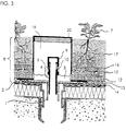
- FIG. 2 shows an example of extensive green roofs, in which another embodiment of an inventive Water drainage system is used.
- the water drainage system corresponds essentially to that which was discussed in connection with Fig. 1.
- Only the top one End region 6 of inner tube 4 has through openings 5 on.
- This float causes that the inner tube more or less depending on the water level is pulled far out of the water drain pipe 1.
- This has the consequence that regardless of the height of the water level the water pressure with which the water flows through the Through openings 5 flows into the inner tube 4, practical remains constant. So it is achieved in this way that the amount of water draining from the roof also changes practically does not change over time, even if the rainfall vary widely. Compliance with the flow rate is therefore guaranteed in a particularly constant manner.
- the inner tube 4 is with a small gap in the water drain pipe plugged in.
- the space is thin Filled water film on which the inner pipe in the water drain pipe can slide up and down.
- Figure 3 shows the use of a water drainage system according to the invention in connection with an intensive green roof with water retention.
- a sufficient Granting water supply is in the layer structure 8, which is arranged on the roof surface 2, a water reservoir 12 available.
- the maximum water level, with which the water 3 in the long run within the Layer structure 8 can accumulate, is determined by the height of the another tube 9 specified. As soon as this maximum water level a predetermined proportion flows of water 3 through the through openings 5 of the inner tube 4, which is inserted into the further tube 9 is.
- the flow rate per unit of time is again over the Number and / or size of the through openings 5 controlled.
- the arrangement shown ensures that it is on the roof falling water with a long-term Level above the desired maximum water level can. At the same time, however, excess is prevented Water runs out of the roof in an uncontrolled manner. By the continuous drain of the excess water will also prevents permanent waterlogging which affects plant growth. With especially sensitive plants can be useful the drain layer 15, which is through the filter mat 16 separated from the plant substrate 17, so as to enlarge the plant substrate 17 and the plants growing on it 7 continue to be removed from the water reservoir 12.
- the Layer construction materials used on the modified Adjust water retention can prove advantageous to use.
- materials can be used with a larger pore volume better absorb the more abundant water can.
- the improved water balance allows the Planting with more demanding plants than before with comparable layer structures was possible - and that with both intensive and extensive greening.
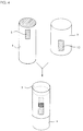
- Figure 4 shows a particularly preferred embodiment of further tube 9 and inner tube 4.
- the design of the two parts shown makes it possible in a particularly simple manner to adapt the water drainage system according to the invention to the conditions found and the intended use.
- Figure 4a shows an inner tube 4, which is closed at its upper end and has a plurality of slot-shaped through openings 5 in its tubular jacket.
- Figure 4b shows an associated further pipe 9, which is open on both sides and also in its tubular casing has slot-shaped through openings 10.
- the outside diameter of the further tube 9 corresponds essentially the inner diameter of the inner tube 4, so that the Inner tube, when it is attached to the other tube, on this.
- Figure 4c shows the inner tube 4 and another tube 9 in the assembled state.
- the two tubes are shifted against each other so that the through openings 5 and 10 each partially coincide with each other.
- a water drain pipe 1 not shown.
- the size of the resulting through openings can be varied practically continuously through both tubes.
- the outflow quantities which can flow off per unit of time through the arrangement shown can be set to the desired values in a very simple manner.
- the arrangement shown is therefore suitable for a large number of applications without having to make changes to the individual components of the water drainage system according to the invention.
- scalings may be present on the inner pipe 4 and / or the further pipe 9, which, however, are not shown in the illustration for simplification.
- the water level was lower than the layer height of the storage medium that was applied to the roof surface. Gravel and expanded slate of the specified grain sizes were used as the storage medium.
- the time for which the water on the roof surface is retained on this depends on the one hand on the type of storage medium and on the other hand on the water level and the available cross-section of the drain.
- the running speed is reduced with decreasing discharge cross-section and increasing storage capacity of the storage medium.
- the outflow delay values are many times higher than for the systems of the prior art, in which water is discharged into the sewage system practically without delay.
- the values shown show that it is possible to extend the drainage of water from the roof surface considerably compared to conventional systems. On the one hand, this enables compliance with specified wastewater values, and on the other hand, the water retained on the roof is available longer for any existing planting. This increased water supply can positively influence the growth of the plants on the roof.
- the flow rate of the water can be influenced in a targeted manner by setting the arrangement, number and / or size of the through openings of the inner tube and / or the inner diameter of the inner tube of the water drainage system according to the invention in the manner described above.
- the water drainage system according to the invention can thus be specifically adapted in a simple manner to the conditions found and the intended use.
Abstract
Description
Die Erfindung betrifft ein Wasserabflußsystem, insbesondere ein Wasserabflußsystem für Dachflächen, und besonders ein solches System, welches verhindert, daß Regenwasser, welches auf einer Fläche niedergeht, in im wesentlichen unverminderter Menge und ohne zeitliche Verzögerung abfließt.The invention relates to a water drainage system, in particular a water drainage system for roof surfaces, and especially one such a system, which prevents rainwater, which descended on one surface, in essentially undiminished Flows out and without delay.
Die Versiegelung des Bodens führt insbesondere in Städten dazu, daß die bei starken Regenfällen niedergehende Wassermenge von der Kanalisation nicht bewältigt werden kann. Als Folge hiervon kommt es zu Überschwemmungen von Straßen, Bürgersteigen usw.. Herkömmliche Gebäudebedachungen leiten das auf ihnen niedergegangene Regenwasser praktisch vollständig und ohne zeitliche Verzögerung vom Dach wieder ab. Dagegen erfolgt die Abgabe des Regenwassers von begrünten Dächern mit zeitlicher Verzögerung. Der Grund hierfür liegt darin, daß die Pflanzen und das Substrat, auf welchem die Pflanzen angepflanzt sind, Regenwasser speichern und nur verzögert abgeben. Zudem ist die Menge des abgegebenen Wassers geringer, da ein Teil der Niederschlagsmenge über die Bodenfläche verdunstet und ein anderer Teil von den Pflanzen verbraucht wird. Gegenüber herkömmlichen, nicht bepflanzten Dächern weisen begrünte Dächer also den Vorteil auf, daß der auf ihnen niedergegangene Niederschlag in reduzierter Menge und mit zeitlicher Verzögerung an die Kanalisation abgegeben wird. The sealing of the soil leads particularly in cities that the amount of water falling during heavy rainfall can not be managed by the sewage system. As As a result, road flooding occurs Sidewalks, etc. Guide conventional building roofs the rainwater that has fallen on them is practically complete and off the roof without delay. In contrast, rainwater is released from green areas Roofs with a time delay. The reason for this is in that the plants and the substrate on which the Plants are planted, save rainwater and only deliver delayed. In addition, the amount of dispensed Water is lower because part of the rainfall is above the floor surface evaporates and another part of the Plants is consumed. Compared to conventional, not planted roofs therefore have the advantage of green roofs that the precipitation that has fallen on them is reduced Quantity and with a time delay to the sewage system is delivered.
Der Aufbau des Pflanzsubstrats für die Dachbegrünung unterscheidet sich je nach Art der Pflanzen, welche auf dem Dach angepflanzt werden sollen. Es sind sowohl ein- als auch mehrschichtige Aufbauten bekannt. Üblicherweise gilt, daß die Anzahl der Schichten zunimmt, je anspruchsvoller die Pflanzen werden. Sollen beispielsweise Stauden, Sträucher oder Bäume gepflanzt werden, sind üblicherweise mehrschichtige Aufbauten erforderlich, und um die Pflanzen hinreichend mit Wasser zu versorgen, ist eine Anstaubewässerung notwendig. Ein Schichtaufbau für eine derartige Intensivbegrünung umfaßt also ein Wasserreservoir, aus dem die Pflanzen kontinuierlich mit Feuchtigkeit versorgt werden können.The structure of the planting substrate for green roofs differs depending on the type of plants that are on the roof should be planted. There are both one and one multi-layer structures known. Usually it applies that the more demanding the number of shifts increases Plants. For example, perennials, shrubs or trees are planted are usually multi-layered Superstructures required and sufficient for the plants Providing with water is pond irrigation necessary. A layered structure for such intensive green roofing thus comprises a water reservoir from which the Plants are continuously supplied with moisture can.
Fig. 5 zeigt einen derartigen Schichtaufbau für die Intensivbegrünung
mit Wasseranstau. In der Figur ist ein Teilquerschnitt
durch die auf dem Dach aufgebrachten Schichten
im Bereich um ein Wasserabflußrohr 1 dargestellt, welches
in einem mit einem Deckel 20 verschlossenen Schacht 19 angeordnet
ist. Mit Hilfe des Wasserabflußrohres 1 wird Überschußwasser
vom Dach in die Kanalisation abgeleitet. Die
Menge des Überschußwassers ist, verglichen mit einem unbegrünten
Dach, wegen der Retentionseigenschaften der auf
der Dachfläche 2 aufgebrachten Schichtstruktur 8 und der
Bepflanzung 7 reduziert. Abhängig vom Schichtaufbau und den
verwendeten Materialien können Wasserabflußmengen eingestellt
werden, die zwischen 0 und 70 % des auf der Dachfläche
niedergegangenen Wassers liegen.
Um die Pflanzen 7 ausreichend mit Wasser versorgen zu können,
ist im Schichtaufbau 8 ein Wasserreservoir 12 vorgesehen.
Innerhalb des Schichtaufbaus 8 ist ein Wasserleitprofil
angeordnet, das den Schichtaufbau in vertikaler Richtung
entwässert und den Fluß des Wassers in der Dachebene
begünstigt. Zwischen Wasserleitprofil und Dachfläche 2
sind eine Wurzelschutzbahn 13 und eine Schutzlage 14 vorhanden,
die ein Vordringen der Pflanzenwurzeln in Richtung
auf die Dachfläche verhindern und so die Dichtigkeit des
Daches gewährleisten. Oberhalb des Wasserleitprofils 12 ist
eine Drainschicht 15 angeordnet, welche verhindern soll,
daß sich im Wurzelbereich der Pflanzen 7 Staunässe bildet,
welche das Wachstum der Pflanzen beeinträchtigen kann.
Durch eine Filtermatte 16 von der Drainschicht 15 getrennt,
befindet sich das Pflanzsubstrat 17, das eigentliche Wachstumssubstrat
für die Pflanzen 7.5 shows such a layer structure for intensive greening with water accumulation. The figure shows a partial cross section through the layers applied to the roof in the area around a
In order to be able to supply the
Der maximale Wasserstand, der sich im Wasserreservoir 12
des Schichtaufbaus 8 einstellen kann, wird durch die Ausgestaltung
des Wasserabflußsystems im Bereich des Wasserabflußrohres
1 vorgegeben. In dieses Wasserabflußrohr ist ein
Innenrohr 4 eingesteckt und gegen das Wasserabflußrohr 1
mit Hilfe von zwei Dichtringen 18 wasserdicht abgeschlossen.
Das zylindrische Innenrohr 4 ist so in das Wasserabflußrohr
1 eingesteckt, daß seine obere Stirnseite in einer
Höhe oberhalb der Dachfläche 2 liegt, welche dem gewünschten
maximalen Wasserstand im Schichtaufbau entspricht.
Fällt Niederschlag auf das begrünte Dach, gelangt das Überschußwasser,
welches nicht von den oberen Schichten des
Schichtaufbaus 8 und den Pflanzen 7 aufgenommen wurde, in
das Wasserreservoir 12. Dort staut es sich solange auf, bis
sich der durch die Position des Innenrohres 4 vorgegebene
maximale Wasserstand eingestellt hat. Weiteres Wasser 3,
welches in das Wasserreservoir 12 gelangt, fließt über das
Innenrohr 4 über, gelangt durch die obere Öffnung des Innenrohrs
4 in das Innere des Rohres hinein und fließt von
dort durch das Wasserabflußrohr 1 vom Dach ab. Ist der maximale
Wasserstand also einmal erreicht, wird alles zusätzlich
in das Wasserreservoir 12 gelangende Überschußwasser 3
ungehindert und ohne zeitliche Verzögerung in die Kanalisation
abgeleitet. Der Durchmesser des Innenrohres ist so
groß, daß der maximale Wasserstand praktisch nie überschritten
wird, da alles überschüssige Wasser ungehindert
und unverzögert abfließt. In diesem Fall ist also kein Wasserrückhalt
mehr gewährleistet, und die Grenzwerte für die
vom Dach abgeleiteten Abwassermengen können nicht mehr eingehalten
werden.The maximum water level in the
Bei der herkömmlichen Gestaltung der Abflußsysteme von Dachaufbauten mit Intensivbegrünung ist also - trotz der Vorteile die ein begrüntes Dach gegenüber einem nicht begrünten Dach bietet - nicht in jedem Fall gewährleistet, daß die vorgeschriebenen Abwasserwerte eingehalten werden und ein ausreichender Wasserrückhalt sichergestellt werden kann.In the conventional design of the drainage systems from Roof structures with intensive greenery is - despite the Advantages that a green roof does not have over you green roof offers - not guaranteed in every case, that the prescribed wastewater values are complied with and sufficient water retention can be ensured can.
Dies gilt in verstärktem Maß für Dächer, welche keine Dachbegrünung aufweisen. Bei nichtbegrünten Dachflächen war es bisher grundsätzlich unerwünscht, daß es zu einem Anstau von Regenwasser auf dem Dach kam. Abgesehen von der Verschlammung und Verkrustung der Dächer bestand die Gefahr, daß Frostdruck und Bewegungen einer auf dem Dach gebildeten Eisdecke zu einer Beschädigung der Dachkonstruktion und zu Undichtigkeiten des Daches führten. Auch auf Kiesdächern war daher der Anstau von Wasser bislang unerwünscht.This applies to a greater extent to roofs that do not have green roofs exhibit. It was with green roof areas So far basically undesirable that there is a build-up came from rainwater on the roof. Except for the silting up and encrustation of the roofs there was a risk that frost pressure and movements of one formed on the roof Ice sheet to damage the roof structure and to Leaks in the roof resulted. Even on gravel roofs the accumulation of water has so far been undesirable.
Der Erfindung liegt die Aufgabe zugrunde, ein Waserabflußsystem anzugeben, das eine verbesserte Wasserretention aufweist und den unkontrollierten Ablauf von Wasser von einer Fläche weitestgehend verhindert.The invention has for its object to provide a water drainage system that has improved water retention and largely prevents the uncontrolled outflow of water from one surface.
Die Erfindung soll vermeiden, daß überhöhte Abwasserspitzen auftreten und vorgegebene Abwasserwerte nicht eingehalten werden können. Das erfindungsgemäße Wasserabflußsystem soll sich insbesondere für begrünte Dächer eignen und sicherstellen, daß trotz einer verzögerten Wasserabgabe in die Kanalisation keine dauerhafte Staunässe entsteht, welche das Pflanzenwachstum beeinträchtigen könnte. Andererseits soll sich das erfindungsgemäße Wasserabflußsystem auch für die Verwendung auf unbegrünten Dächern, Terrassen usw. eignen und eine vergleichmäßigte Wasserabgabe sicherstellen. Schädigungen des Untergrunds durch Frostdruck oder Reibung einer Eisdecke sollen vermieden werden. Zudem sollte das erfindungsgemäße Wasserabflußsystem an die örtlich vorgefundenen Bedingungen sowie an die beabsichtigte Anwendung, beispielsweise an die Art der Bepflanzung, flexibel anpaßbar, dabei aber einfach aufgebaut sein.The invention is intended to avoid excessive wastewater peaks occur and specified wastewater values are not adhered to can be. The water drainage system according to the invention is intended are particularly suitable for green roofs and ensure that despite delayed water delivery into the Sewerage does not cause permanent waterlogging, which could affect plant growth. On the other hand the water drainage system according to the invention is also intended for suitable for use on green roofs, patios, etc. and ensure even water delivery. Damage to the surface due to frost pressure or friction an ice sheet should be avoided. In addition, that should water drainage system according to the invention to the locally found Conditions and the intended application, for example to the type of planting, flexibly adaptable, but just be set up.
Die Lösung dieser Aufgaben gelingt mit dem Wasserabflußsystem
gemäß Anspruch 1. Weitere Ausbildungsformen ergeben
sich aus den Unteransprüchen. Die Erfindung betrifft außerdem
die Verwendung des Wasserabflußsystems gemäß Ansprüchen
21 und 22.These tasks are solved with the water drainage system
according to
Im einzelnen betrifft das in Anspruch 1 beanspruchte Wasserabflußsystem
ein System, welches wenigstens ein Wasserabflußrohr,
durch welches auf einer Fläche befindliches
Wasser abgeleitet wird, sowie ein über die Fläche vorstehendes
Innenrohr umfaßt. Wasserabflußrohr und Innenrohr
sind dicht schließend miteinander verbunden, so daß von der
Fläche ablaufendes Wasser im wesentlichen ausschließlich
über das Innenrohr in das Wasserabflußrohr gelangt. Erfindungsgemäß
ist das Innenrohr so ausgebildet, daß nur ein
vorgegebener, begrenzter Anteil des Wassers, welches durch
das Innenrohr in das Wasserabflußrohr einleitbar ist, pro
Zeiteinheit in das Innenrohr und von dort in das Wasserabflußrohr
gelangen kann.In particular, the water drainage system claimed in
Im Unterschied zu den Wasserabflußsystemen des Standes der Technik wird also diejenige Menge an Wasser, welche auf einer zu entwässernden Fläche niedergegangen ist und welche - gegebenenfalls nach Überschreiten eines vorgegebenen maximalen Wasserstands auf der Fläche - von der Fläche abgeleitet werden soll, nicht ohne zeitliche Verzögerung und so schnell wie möglich von der Fläche abgeleitet, sondern der Abfluß des überschüssigen Wassers erfolgt mit zeitlicher Verzögerung, so daß ein Großteil des über das Innenrohr in das Wasserabflußrohr abzuleitenden Wassers zunächst auf der Fläche zurückgehalten wird. Dies wird dadurch erreicht, daß die Fläche der Durchgangsöffnungen, durch welche das abzuleitende Wasser in das Innenrohr eintreten kann, derart begrenzt wird, daß nicht sofort alles abzuleitende Wasser in das Innenrohr eintreten kann. Die Durchlaßfläche für das Wasser wird dabei so gewählt, daß nur die gewünschte Menge an Wasser pro Zeiteinheit über das Innenrohr abfließen kann. Auf diese Weise ist gewährleistet, daß nicht sofort alles auf der Fläche befindliche und durch das Innenrohr ableitbare Wasser von der Fläche abgeleitet wird. Vielmehr kann ein definierter und verlangsamter Wasserabfluß sichergestellt werden, der es ermöglicht, eventuell vorgegebene Abwasserwerte einhalten zu können.In contrast to the water drainage systems of the prior art Technology is the amount of water that is on an area to be drained has fallen and which - if necessary after exceeding a predetermined maximum Water level on the surface - derived from the surface should not be without a time delay and such derived from the surface as quickly as possible, but the Excess water is drained at a time Delay so that much of the over the inner tube in the water drain pipe to be drained water first on the Area is retained. This is achieved in that the area of the through openings through which the to be discharged Water can enter the inner tube, limited in this way is that not all of the water to be drained off immediately the inner tube can enter. The passage area for that Water is chosen so that only the desired amount of water per unit time drain through the inner tube can. This ensures that not immediately everything on the surface and through the inner tube derivable water is derived from the area. Much more can ensure a defined and slow water drainage be, which makes it possible, possibly predetermined To be able to comply with wastewater values.
Durch geeignete Wahl der Ausgestaltung des Innenrohres eignet sich das erfindungsgemäße Wasserabflußsystem sowohl für Flächen, auf denen ein Wasseranstau vorgesehen ist und überschüssiges Wasser dann mit zeitlicher Verzögerung durch das Innenrohr abgeleitet wird, sobald ein bestimmter Wasserstand überschritten ist, als auch für Fälle ohne Wasseranstau, bei denen mit der erfindungsgemäßen zeitlichen Verzögerung das auf der Fläche befindliche Wasser möglichst vollständig abgeleitet werden soll.By a suitable choice of the design of the inner tube the water drainage system according to the invention is both suitable for areas on which water is planned and excess water then with a time delay the inner tube is drained off as soon as a certain water level is exceeded, as well as for cases without water accumulation, in those with the time delay according to the invention the water on the surface if possible to be fully derived.
Die zeitlich verzögerte Ableitung überschüssigen Wassers kann in einer Ausbildungsform der Erfindung dadurch erreicht werden, daß das Innenrohr an seinem über die Fläche vorstehenden Ende offen ist und der Innendurchmesser des Innenrohres so gewählt wird, daß sich die gewünschte Abflußmenge pro Zeiteinheit einstellt. Ein entsprechendes Wasserabflußsystem kann beispielsweise grundsätzlich wie das in Fig. 5 dargestellte System aufgebaut sein. Jedoch wird der Einlaßquerschnitt für das abzuleitende Wasser sehr viel geringer sein als derjenige des Systems des Standes der Technik, bei welchem ein unverzögerter Abfluß des überschüssigen Wassers beabsichtigt war. Das erfindungsgemäße Innenrohr, welches im Zusammenhang mit der in Fig. 5 dargestellten Anordnung verwendet werden kann, kann über seine gesamte Länge einen einheitlichen Innendurchmesser aufweisen, oder aber es ist nur in einem Teilbereich auf einen geeigneten Innendurchmesser verengt.The delayed drainage of excess water can be achieved in one embodiment of the invention be that the inner tube at its over the area projecting end is open and the inner diameter of the Inner tube is chosen so that the desired flow rate per unit of time. A corresponding one For example, water drainage system can basically like the system shown in Fig. 5 can be constructed. However becomes the inlet cross-section for the water to be drained very be much less than that of the system of the state the technique in which an instant drain of the excess Water was intended. The invention Inner tube, which in connection with that shown in Fig. 5 Arrangement can be used via its have a uniform inner diameter over the entire length, or it is only in a partial area on one suitable inner diameter narrowed.
Bei der beschriebenen Variante des erfindungsgemäßen Wasserabflußsystemes ist es möglich, daß sich bei einem sehr verlangsamten Ablauf des Wassers und bei sehr starken Niederschlägen ein sehr hoher Wasserstand auf der zu entwässernden Fläche einstellt. In einigen Fällen kann es jedoch erwünscht sein, daß ein bestimmter maximaler Wasserstand nicht überschritten wird. Dies gilt beispielsweise dann, wenn auf der zu entwässernden Fläche eine Bepflanzung vorhanden ist, deren Wurzeln durch einen zu hohen Wasserstand und Staunässe im Wurzelbereich beschädigt werden können. Um den Anstieg des Wasserspiegels über den maximal erwünschten Wasserstand hinaus zu verhindern, kann im Bereich der zu entwässernden Fläche ein Notablauf vorhanden sein. Durch diesen Notablauf wird Wasser, welches nach Erreichen des maximal erwünschten Wasserstandes auf die zu entwässernde Fläche niedergeht, sofort und ohne zeitliche Verzögerung von der Fläche abgeführt. Der Einlaß des Notablaufes liegt dabei bezüglich der Höhe weiter von der zu entwässernden Fläche entfernt als die Eingangsöffnung(en) des Innenrohres. Der Auslaß des Notablaufs kann beispielsweise entweder in die Kanalisation münden, oder das überschüssige Wasser wird an der Gebäudefassade abgeleitet. In the described variant of the water drainage system according to the invention it is possible that in a very slow flow of water and very heavy rainfall a very high water level on the to draining area. In some cases it can however, it may be desirable to have a certain maximum water level is not exceeded. This applies, for example when there is planting on the area to be drained is present, the roots of which are due to a too high water level and waterlogging in the root area can be damaged can. To increase the water level above the maximum Preventing desired water levels can be in the area there is an emergency drain on the area to be drained his. Due to this emergency drain water, which after reaching the maximum desired water level towards the draining area, immediately and without time Delay dissipated from the area. The admission of the emergency drain is further from the height draining area away as the entrance opening (s) of the inner tube. The outlet of the emergency drain can, for example either into the sewage system, or the excess Water is drained from the building facade.
In einer zweiten erfindungsgemäßen Variante, welche alternativ oder aber auch ergänzend zu der vorstehend beschriebenen Variante eingesetzt werden kann, wird der verzögerte Wasserablauf dadurch erreicht, daß erfindungsgemäß im Rohrmantel des Innenrohrs, in dem Bereich, in welchem das Innenrohr über die Fläche vorsteht, wenigstens eine Durchgangsöffnung vorhanden, durch welche das auf der Fläche stehende Wasser ins Innere des Innenrohrs durchtreten und von dort durch das Wasserabflußrohr abfließen kann. Vorzugsweise weist das Innenrohr eine Vielzahl von Durchgangsöffnungen auf.In a second variant according to the invention, which is alternative or in addition to that described above Variant can be used, the delayed Water drainage achieved in that according to the invention in the pipe jacket of the inner tube, in the area in which the inner tube protrudes beyond the surface, at least one through opening through which that is on the surface through standing water inside the inner tube and from there can drain through the water drain pipe. Preferably the inner tube has a plurality of through openings on.
Anzahl und Größe der Durchgangsöffnungen werden zweckmäßig so gewählt, daß pro Zeiteinheit eine vorgegebene Menge Wasser von der Fläche ablaufen kann. So kann sichergestellt werden, daß pro Zeiteinheit nur eine begrenzte Menge an Wasser von der zu entwässernden Fläche abläuft und die vorgegebenen Abwasserwerte eingehalten werden. Selbstverständlich können auch mehrere erfindungsgemäße Wasserabflußsysteme auf einer Fläche verwendet werden.The number and size of the through openings are appropriate chosen so that a predetermined amount per unit of time Water can run off the surface. This can ensure be that only a limited amount of time per unit of time Water drains from the area to be drained and the specified Waste water values are complied with. Of course can also several water drainage systems according to the invention can be used on one surface.
Um zu verhindern, daß unkontrolliert Wasser in das Innenrohr eindringt, ist das Innenrohr zweckmäßig an seinem oberen, über die Fläche vorstehenden Ende verschlossen. In einer alternativen Ausführungsform kann das Innenrohr so lang ausgebildet sein, daß es weiter über die zu entwässernde Fläche vorsteht als der zu erwartende maximale Wasserstand auf dieser Fläche. In beiden Fällen wird verhindert, daß Wasser nach dem Überschreiten der maximal vorgesehenen Anstauhöhe durch das obere, offene Ende des Ableitungsrohrs einer bekannten Entwässerungsanordnung, wie sie im Zusammenhang mit Figur 5 beschrieben wurde, unkontrolliert abläuft. To prevent uncontrolled water from entering the inner tube penetrates, the inner tube is expedient at its upper, closed over the surface protruding end. In an alternative embodiment, the inner tube be long that it continues beyond the drainage Area protrudes than the expected maximum water level on this area. In both cases it is prevented that water after exceeding the maximum intended Accumulation height through the upper, open end of the drain pipe a known drainage arrangement, such as was described in connection with Figure 5, uncontrolled expires.
Das erfindungsgemäße Wasserabflußsystem kann sowohl zur
Entwässerung von Flächen verwendet werden, auf denen der
Anstau eines definierten Wasserreservoirs vorgesehen ist,
als auch auf solchen Flächen, von denen das Wasser vollständig
ablaufen soll.
Im ersteren Fall wird das Innenrohr nur in seinem oberen
Endbereich mit einer oder mehreren Durchgangsöffnungen versehen,
während in dem Bereich, welcher der zu entwässernden
Fläche benachbart ist, keine Öffnungen vorgesehen sind. Der
über die Fläche vorstehende Bereich des Innenrohres wird
dabei in einer Höhe nicht mit Durchgangsöffnungen versehen,
welche der maximal gewünschten Stauhöhe des Wassers auf der
Fläche entspricht. Bis zu dieser Höhe kann also auf der
Fläche niedergehendes Wasser angestaut werden. Steigt der
Wasserspiegel über dieses Niveau, fließt das Wasser durch
die wenigstens eine Durchgangsöffnung ins Innere des Innenrohres
und von dort über das Wasserabflußrohr von der
Fläche ab. Wie erwähnt, kann die Abflußmenge pro Zeit durch
geeignte Wahl der Anzahl und Größe der Durchgangsöffnungen
auf das für die zugeordnete Einzugsfläche gewünschte Maß
eingestellt werden, so daß ein kontinuierliches Abfließen
des Wassers sichergestellt ist.The water drainage system according to the invention can be used both for the drainage of areas on which the accumulation of a defined water reservoir is provided, as well as on areas from which the water is to run off completely.
In the former case, the inner tube is provided with only one or more through openings in its upper end region, while no openings are provided in the region which is adjacent to the surface to be drained. The area of the inner tube protruding above the surface is not provided with through openings at a height which corresponds to the maximum desired accumulation height of the water on the surface. Up to this height, water falling on the surface can be dammed up. If the water level rises above this level, the water flows through the at least one through opening into the interior of the inner pipe and from there via the water drainage pipe from the surface. As mentioned, the flow rate per time can be adjusted to the desired level for the assigned catchment area by a suitable choice of the number and size of the through openings, so that a continuous flow of the water is ensured.
Soll andererseits kein Wasserreservoir auf der Fläche verbleiben, wird das Innenrohr auch in seinem unteren Bereich mit Durchgangsöffnungen versehen, so daß das gesamte auf der Fläche angestaute Wasser allmählich über das Innenrohr abfließen kann.On the other hand, if no water reservoir is to remain on the surface, the inner tube is also in its lower area provided with through openings so that the whole on water accumulated gradually over the inner tube can drain off.
Die Erfindung bietet zudem den Vorteil, das Wasserabflußsystem gezielt an die jeweils vorgefundenen Bedingungen und Anwendungsgebiete anpassen zu können. Beispielsweise können die örtlichen Niederschläge sehr stark differieren und es zweckmäßig erscheinen lassen, die Abflußmengen entsprechend einzustellen. Besonders wichtig ist dies im Fall begrünter Dachflächen, bei denen Staunässe zu einer Beeinträchtigung des Pflanzenwachstums führen kann. Andererseits kann es gerade in trockeneren und niederschlagsärmeren Gebieten zweckmäßig sein, auf den begrünten Flächen niedergehendes Wasser länger für die Pflanzen zur Verfügung zu halten und so deren Wachstum positiv zu beeinflußen. Dies gilt insbesondere für extensiv begrünte Flächen. Auch unterschiedliche Arten von Schichtaufbauten für die Dachbegrünung sowie unterschiedlicher Arten der Bepflanzung machen unterschiedliche Arten der Be- und Entwässerung erforderlich. Gelegentlich kann auch eine Anpassung der Entwässerung an die jahreszeitlich unterschiedlichen Bedingungen zweckmäßig sein.The invention also has the advantage of the water drainage system targeted to the conditions found and To be able to adapt application areas. For example the local rainfall varies greatly and it make it seem appropriate, the flow rates accordingly adjust. This is particularly important in the case of greenery Roof areas where waterlogging is a nuisance of plant growth can result. On the other hand, it can especially in drier and less precipitation areas be expedient, descending on the green areas To keep water available for the plants longer and so to positively influence their growth. This is especially true for extensive green areas. Different too Types of layered structures for green roofs as well different types of planting make different Types of irrigation and drainage required. Occasionally can also adapt drainage to the seasonally appropriate conditions appropriate his.
Die Erfindung ermöglicht eine einfache Anpassung des Wasserabflußsystems an die beschriebenen Bedingungen. So kann die Anstauhöhe des Wassers auf der zu entwässernden Fläche auf einfache Weise dadurch eingestellt werden, daß die Höhe desjenigen Bereiches des Innenrohres, der von Durchgangsöffnungen frei bleiben soll, entsprechend gewählt wird. Bei der ersten erfindungsgemäßen Variante, bei welcher die Abflußmenge über den Innendurchmesser des Innenrohres gesteuert wird, wird die Anstauhöhe des Wassers über die Höhe geregelt, mit welcher das Innenrohr über die Fläche vorsteht.The invention enables easy adaptation of the water drainage system to the conditions described. So can the accumulation height of the water on the area to be drained can be easily adjusted by adjusting the height that area of the inner tube that of through openings should remain free, is chosen accordingly. At the first variant according to the invention, in which the discharge amount controlled via the inner diameter of the inner tube the accumulation height of the water is regulated by the height, with which the inner tube protrudes over the surface.
Die Schnelligkeit, mit welcher auf der Fläche angesammeltes Wasser von dieser Fläche abgeleitet wird, kann, wie bereits beschrieben, durch geeignete Wahl der Anzahl und Größe der Durchgangsöffnungen im Innenrohr oder den Durchlaßquerschnitt des Innenrohres eingestellt werden. Entsprechend ergibt sich hieraus der Zeitraum, über welchen angestautes Wasser auf der Fläche zur Verfügung bleibt und beispielsweise von auf dieser Fläche wachsenden Pflanzen aufgenommen und genutzt werden kann. Dabei kann trotz verbesserter Retentionseigenschaften verhindert werden, daß sich Wasser dauerhaft anstaut, da durch die Konstruktion des erfindungsgemäßen Wasserabflußsystems für einen kontinuierlichen Wasserabfluß gesorgt ist, wenn der Wasserstand eine vorgegebene Höhe übersteigt. Schädigungen von Bepflanzungen auf der Fläche durch ständige Staunässe können somit vermieden werden.The speed with which accumulated on the surface Water drained from this area can, as already described by appropriate choice of the number and size of Through openings in the inner tube or the passage cross section of the inner tube can be adjusted. Corresponding this gives the period over which pent-up Water remains available on the area and for example from plants growing on this area and can be used. This can be done despite improved retention properties be prevented that water permanently dammed up because of the construction of the invention Water drainage system for a continuous Water drainage is provided when the water level is a predetermined one Height exceeds. Damage to plantings the area due to constant waterlogging can thus be avoided become.
Für die Anpassung des erfindungsgemäßen Wasserabflußsystems an die jeweiligen örtlichen Gegebenheiten geht man zweckmäßig so vor, daß das erforderliche Retentionsvermögen des Systems bzw. die geeignete Wasserabflußmenge pro Zeit anhand der für die Region verfügbaren Niederschlagsmengen und deren zeitlicher Verteilung ermittelt wird. Die erforderlichen Niederschlagswerte sind beispielsweise von den regionalen Wetterstationen erhältlich. Anordnung, Anzahl und Größe der Durchgangsöffnungen bzw. der Innendurchmesser des Innenrohres können zweckmäßig mit Hilfe eines Datenverarbeitungssystems errechnet werden, wobei von bekannten und bewährten Systemen und Verwendungen als Standard ausgegangen werden kann. In dem Berechnungsprogramm können zusätzlich folgende weitere Parameter berücksichtigt werden: die Art der Bepflanzung; die Wasserrückhalteeigenschaften der zu entwässernden Fläche; Wasserverlust durch Verdunstung; die Art des Schichtaufbaus bei einer Dachbegrünung sowie die Wasserretentionseigenschaften dieses Schichtaufbaus; die gewünschten maximalen Abflußmengen pro Zeiteinheit oder gegebenenfalls vorgeschriebene Abflußmengen pro Jahr.For the adaptation of the water drainage system according to the invention one appropriately goes to the respective local conditions so that the required retention capacity of the Systems or the appropriate amount of water runoff per time the amount of precipitation available for the region and their temporal distribution is determined. The necessary Precipitation values are, for example, from the regional ones Weather stations available. Order, number and Size of the through openings or the inner diameter of the Inner tube can be useful with the help of a data processing system can be calculated from known and proven systems and uses as a standard can be. In the calculation program you can also the following additional parameters are taken into account: the Type of planting; the water retention properties of the area to be drained; Water loss through evaporation; the type of layer structure for green roofs and the water retention properties of this layer structure; the desired maximum discharge quantities per unit of time or where appropriate, prescribed discharge quantities per year.
Die Verteilung der Durchgangsöffnungen entlang des Innenrohrs muß erfindungsgemäß nicht gleichmäßig sein. Vielmehr können sich Anzahl und/oder Größe der Durchgangsöffnungen in axialer Richtung des Innenrohrs ändern. Auf diese Weise läßt sich ein zeitlich veränderlicher Wasserabfluß einstellen. The distribution of the through openings along the inner tube does not have to be uniform according to the invention. Much more can vary the number and / or size of the through openings change in the axial direction of the inner tube. In this way a time-variable water drain can be set.
Beispielsweise kann es bei begrünten Dachflächen zweckmäßig sein, bei einem sehr hohen Wasserstand für einen zunächst schnelleren Abfluß des Wassers zu sorgen. Dies gelingt dadurch, daß Anzahl und/oder Größe der Durchgangsöffnungen in Richtung auf den oberen Endbereich des Innenrohres hin zunehmen. Auf diese Weise kann verhindert werden, daß sich über längere Zeit ein hoher Wasserstand auf dem Dach einstellt, der durch Staunässe im Wurzelbereich zu einer Schädigung der Bepflanzung führt. Ist dagegen der Wasserstand auf ein nicht mehr schädliches Niveau abgesunken, kann ein verlangsamter Abfluß des Wassers vom Dach zweckmäßig sein, um die Pflanzen über einen längeren Zeitraum mit einem Wasservorrat zu versorgen.For example, it can be useful for green roof areas be at a very high water level for one initially to ensure faster water drainage. This is achieved by that number and / or size of the through openings in Increase towards the upper end of the inner tube. In this way, it can be prevented sets a high water level on the roof for a long time, damage caused by waterlogging in the root area the planting leads. However, is the water level may have dropped to a level that is no longer harmful slow drainage of water from the roof may be appropriate, around the plants with water for a long period of time to supply.
Um eine Anpassung des erfindungsgemäßen Wasserabflußsystems
an die jeweils vorgefundenen örtlichen Bedingungen oder die
sich jahreszeitlich ändernden Bedingungen zu ermöglichen,
ist das Wasserabflußsystem besonders bevorzugt so ausgebildet,
daß sich Lage, Anzahl und/oder Größe der Durchgangsöffnungen
variabel verändern lassen.
Hierzu kann einerseits das Innenrohr im Wasserabflußrohr
verschiebbar angeordnet sein. Verschiebt man beispielsweise
ein Innenrohr, dessen über die zu entwässernde Fläche vorstehender
Bereich mit Perforationen versehen ist, in Längsrichtung
im Wasserabflußrohr nach oben oder unten, verändert
sich hierdurch die Anzahl der Durchgangsöffnungen,
durch welche Wasser über das Innenrohr in das Wasserabflußrohr
abfließen kann. Bei weiter aus dem Wasserabflußrohr
herausgezogenem Innenrohr stehen mehr Durchgangsöffnungen
zur Verfügung, und entsprechend vergrößert sich die Wassermenge,
welche pro Zeiteinheit von der Fläche abfließen
kann. In order to enable the water drainage system according to the invention to be adapted to the local conditions found in each case or to the seasonally changing conditions, the water drainage system is particularly preferably designed such that the position, number and / or size of the through openings can be varied variably.
For this purpose, on the one hand, the inner pipe can be arranged displaceably in the water drain pipe. For example, if you move an inner pipe, the area of which protrudes with perforations over the area to be drained, in the longitudinal direction in the water drain pipe up or down, this changes the number of through openings through which water can flow through the inner pipe into the water drain pipe. If the inner tube is pulled further out of the water drainage pipe, more through openings are available, and the amount of water which can flow away from the surface per unit of time increases accordingly.
Verwendet man dagegen ein Wasserabflußsystem mit einem definierten Wasseranstau, kann man durch Verschieben des Innenrohrs im Wasserabflußrohr die Wasserstandshöhe gezielt einstellen, je nachdem, wie weit der nicht perforierte Teil des Innenrohrs aus dem Wasserabflußrohr herausgezogen wird.However, if you use a water drainage system with a defined one Water accumulation can be avoided by moving the Inner tube in the water drainage pipe targeted the water level adjust depending on how far the non-perforated part the inner pipe is pulled out of the water drain pipe.
In einer besonders bevorzugten Ausführungsform ist das erfindungsgemäße
Wasserabflußsystem mit einem weiteren Rohr
ausgestattet, welches radial innerhalb oder außerhalb des
Innenrohres angeordnet ist und an diesem anliegt. Innenrohr
und weiteres Rohr sind dabei gegeneinander verschieb- und/oder
verdrehbar.
Das weitere Rohr kann einerseits frei von Durchgangsöffnungen
sein und dann dazu dienen, bei einem Wasseranstau die
maximale Anstauhöhe des Wassers auf der zu entwässernden
Fläche einzustellen, oder es kann dazu verwendet werden,
eine oder mehrere Durchgangsöffnungen im Innenrohr ganz
oder teilweise abzudecken und so die Abflußmenge an Wasser
einzustellen.In a particularly preferred embodiment, the water drainage system according to the invention is equipped with a further pipe which is arranged radially inside or outside the inner pipe and bears against it. The inner tube and the other tube are displaceable and / or rotatable relative to one another.
The further pipe can on the one hand be free of through-openings and then serve to set the maximum accumulation height of the water on the surface to be drained in the event of a water build-up, or it can be used to cover one or more through-openings in the inner pipe in whole or in part and thus the outflow quantity to adjust to water.
In einer anderen Variante weist auch das weitere Rohr eine oder mehrere Durchgangsöffnungen auf. Zweckmäßig ist diese wenigstens eine Durchgangsöffnung des weiteren Rohres so angeordnet, daß sie sich mit einer zugehörigen Durchgangsöffnung des Innenrohres überlagern läßt. Durch Verschieben und/oder Verdrehen des weiteren Rohres und des Innenrohres gegeneinander kann dann die Anzahl und/oder Größe der resultierenden Durchgangsöffnungen durch beide Rohre stufenlos variiert und den Erfordernissen angepaßt werden.In another variant, the further tube also has one or more through openings. This is useful at least one through opening of the further tube so arranged that they are associated with an opening overlaps the inner tube. By moving and / or twisting the further tube and the inner tube against each other, the number and / or size of the resulting can then Continuous openings through both pipes varied and adapted to the requirements.
Um die den jeweiligen Anforderungen entsprechende Einstellung der beiden Rohre zueinander zu erleichtern, kann auf dem Innenrohr und/oder dem weiteren Rohr eine Skala vorhanden sein. Die Skala kann beispielsweise so aufgebaut sein, daß sich ihr die Position der beiden Rohre zueinander für bestimmte, vorgegebene Abflußmengen entnehmen läßt. Zusätzlich oder alternativ hierzu kann die Skala einen Anhaltspunkt dafür bieten, wie sich die Position der beiden Rohre zueinander bei Anwendung in bestimmten Schichtaufbauten, Flächengrößen, bestimmten Klimazonen, bestimmten Jahreszeiten, bei bestimmten Arten von Bepflanzungen usw. ändert. Die beschriebene bevorzugte Ausgestaltung des erfindungsgemäßen Wasserabflußsystems ermöglicht es, ein und dasselbe System auf eine Vielzahl von Anwendungen anzupassen. Das System ist also äußerst flexibel einsetzbar, ohne dabei kompliziert aufgebaut zu sein.For the setting that corresponds to the respective requirements of the two pipes to each other to facilitate a scale is available for the inner tube and / or the further tube his. The scale can be constructed in this way, for example be that the position of the two pipes to each other for certain, predetermined runoff quantities. Additionally or alternatively, the scale can be a clue offer for how the position of the two Tubes to each other when used in certain layer structures, Area sizes, certain climates, certain seasons, for certain types of plantings, etc. changes. The described preferred embodiment of the invention Drainage system allows one and adapt the same system to a variety of applications. The system can therefore be used extremely flexibly without being complicated.
In einer weiteren bevorzugten Ausführungsform, bei welchem das Wasserabflußsystem ein im Wasserabflußrohr verschiebbares Innen- und/oder weiteres Rohr umfaßt, ist im oberen Endbereich von Innenrohr und/oder weiterem Rohr ein Schwimmkörper vorhanden. Dieser Schwimmkörper sorgt dafür, daß Innenrohr und/oder weiteres Rohr entsprechend dem auf der zu entwässernden Fläche vorherrschenden Wasserstand im Wasserabflußrohr auf- und abbewegt werden. Diese Anordnung kann dazu beitragen, unabhängig vom herrschenden Wasserdruck einen gleichbleibenden Wasserabfluß zu gewährleisten. Bei einem feststehenden Rohr, dessen oberes Ende mit einem Deckel verschlossen ist und welches in seinem oberen Bereich über eine vorgegebene Höhe eine bestimmte Anzahl von Durchgangsöffnungen aufweist, ändert sich die Abflußmenge an Wasser abhängig davon, wie hoch der Wasserüberstand oberhalb der Durchgangsöffnungen ist. Mit zunehmendem Wasserstand erhöht sich der Wasserdruck auf das Rohr, und entsprechend steigt die Wassermenge, welche durch die Durchgangsöffnungen abfließt. Verwendet man dagegen ein entsprechendes Rohr mit einem perforierten oberen Abschnitt und einem perforationsfreien unteren Abschnitt, welches an seinem oberen Rand mit einem Schwimmkörper versehen ist, bleibt der Wasserdruck unabhängig vom Wasserstand konstant, da das Rohr entsprechend dem schwankenden Wasserstand mitbewegt wird.In a further preferred embodiment, in which the water drainage system is slidable in the water drainage pipe Includes inner and / or other tube is in the upper End area of the inner tube and / or another tube Floating bodies available. This float ensures that inner tube and / or another tube according to that the prevailing water level in the area to be drained Water drain pipe can be moved up and down. This arrangement can help regardless of the prevailing water pressure to ensure a constant water drainage. In the case of a fixed pipe, the upper end of which with a Lid is closed and which in its upper area over a given height a certain number of Has through openings, the flow rate changes of water depending on how high the water supernatant is above the through openings. With increasing water level the water pressure on the pipe increases, and accordingly the amount of water that passes through the through openings increases drains away. If you use an appropriate one Tube with a perforated upper section and a perforation-free lower section, which at its upper edge is provided with a floating body, the water pressure remains constant regardless of the water level, because the pipe moves according to the fluctuating water level becomes.
Um die Wartung des erfindungsgemäßen Wasserabflußsystems zu
ermöglichen oder um die gewählten Einstellungen im Laufe
der Zeit verändern zu können, weist das erfindungsgemäße
System zweckmäßig einen Schacht auf, in welchen das Innenrohr
hineinragt und welcher das Innenrohr mit einem Abstand
zu diesem umgibt.
Bei einem System mit Wasseranstau befindet sich der Stauraum
zur Aufnahme des Wassers zweckmäßig im Bereich um dasjenige
Ende des Schachtes, welches der zu entwässernden
Fläche benachbart ist. Stauraum und das Innere des Schachtes
stehen dann über wenigstens einen Durchlaß miteinander
in Verbindung.
Bei Verwendung des erfindungsgemäßen Wasserabflußsystems
zur Entwässerung von begrünten Flächen können oberhalb des
Stauraums wenigstens eine Drainschicht und/oder ein Einschichtsubstrat
und/oder wenigstens eine Pflanzsubstratschicht
angeordnet sein.In order to enable the maintenance of the water drainage system according to the invention or to be able to change the selected settings over time, the system according to the invention expediently has a shaft into which the inner tube projects and which surrounds the inner tube at a distance from it.
In the case of a system with water accumulation, the storage space for holding the water is expediently located in the area around the end of the shaft which is adjacent to the surface to be drained. Storage space and the interior of the shaft are then connected to one another via at least one passage.
When using the water drainage system according to the invention for draining green areas, at least one drain layer and / or a single-layer substrate and / or at least one plant substrate layer can be arranged above the storage space.
Die Erfindung soll nachfolgend am Beispiel von Dachflächen als zu entwässernden Flächen unter Bezugnahme auf eine Zeichnung näher erläutert werden. Darin zeigen schematisch
- Fig. 1a
- einen Querschnitt durch ein Kiesdach im Bereich eines erfindungsgemäßen Wasserabflußsystems;
- Fig. 1b
- das im Wasserabflußsystem gemäß Fig. 1a verwendete Innenrohr in perspektivischer Darstellung;
- Fig. 2
- einen Querschnitt durch ein Kiesdach im Bereich eines weiteren erfindungsgemäßen Wasserabflußsystems;
- Fig. 3
- einen Querschnitt durch ein Dach mit Intensivbegrünung im Bereich eines weiteren Beispiels eines erfindungsgemäßen Wasserabflußsystems;
- Fig. 4
- zwei Komponenten eines erfindungsgemäßen Wasserabflußsystems in zusammengesetztem und nicht zusammengesetztem Zustand und
- Fig. 5
- ein Wasserabflußsystem des Standes der Technik im Querschnitt.
- Fig. 1a
- a cross section through a gravel roof in the area of a water drainage system according to the invention;
- Fig. 1b
- the inner tube used in the water drainage system according to FIG. 1a in a perspective view;
- Fig. 2
- a cross section through a gravel roof in the area of another water drainage system according to the invention;
- Fig. 3
- a cross section through a roof with intensive greenery in the area of another example of a water drainage system according to the invention;
- Fig. 4
- two components of a water drainage system according to the invention in the assembled and disassembled state and
- Fig. 5
- a water drainage system of the prior art in cross section.
Figur 1a beschreibt ein erfindungsgemäßes Wasserabflußsystem, welches auf einem Kiesdach verwendet wird. Das erfindungsgemäße Wasserabflußsystem entspricht in einigen Merkmalen dem in Zusammenhang mit Fig. 5 beschriebenen System des Standes der Technik. Um Wiederholungen zu vermeiden, sollen übereinstimmende Bestandteile nicht erneut beschrieben werden. In allen Figuren bezeichnen gleiche Bezugszeichen gleiche Teile.FIG. 1a describes a water drainage system according to the invention, which is used on a gravel roof. The invention Water drainage system corresponds in some features the system described in connection with FIG. 5 the state of the art. To avoid repetitions, matching components should not be described again become. The same reference numerals are used in all figures same parts.
Der wesentliche Unterschied des erfindungsgemäßen Wasserabflußsystems,
welches in Fig. 1 dargestellt ist, zu dem
Wasserabflußsystem des Standes der Technik gemäß Fig. 5 besteht
in der Ausgestaltung des Innenrohres 4. Während das
Innenrohr des Systems gemäß Fig. 5 oben offen ist und in
seinem Rohrmantelbereich keine Durchgangsöffnungen aufweist,
ist das Innenrohr 4 des erfindungsgemäßen Wasserabflußsystems
in demjenigen Bereich, welcher über die Dachfläche
2 vorsteht, mit einer Vielzahl von Durchgangsöffnungen
5 versehen, die gleichmäßig über diesen Bereich des
Rohres verteilt sind. Zudem ist das Innenrohr 4 in seinem
oberen Bereich verschlossen (vgl. Fig. 1b). Auf diese Weise
wird verhindert, daß bei einem sehr hohen Wasserstand überschüssiges
Wasser von oben in das Innenrohr eindringen und
unkontrolliert abfließen kann. Alternativ wäre es möglich,
das Innenrohr 4 über den maximal zu erwartenden Wasserstand
hinaus nach oben zu verlängern, so daß auch dann, wenn das
Innenrohr oben unverschlossen ist, kein Wasser von oben in
das Rohrinnere eintreten kann. Für den Fall, daß dennoch
einmal der Wasserstand so hoch steigt, daß ein Überlaufen
des Wassers über das obere Bohrende zu befürchten ist, kann
auf der Dachfläche knapp unterhalb des oberen Endes des Innenrohres
ein Notablauf für überschüssiges Wasser vorgesehen
sein, so daß ein Anstieg des Wasserspiegels bis zum
oberen Rohrende vermieden wird.The essential difference of the water drainage system according to the invention,
which is shown in Fig. 1 to the
5 prior art water drainage system
in the design of the
Figur 1 zeigt die Verwendung eines erfindungsgemäßen Wasserabflußsystems
auf einem Kiesdach, bei dem bisher ein sofortiger
Abfluß des auf dem Dach niedergegangenen Wassers
erwünscht war, um zu verhindern, daß sich bei Frost eine
Eisdecke auf dem Dach bildet, welche durch Frostdruck und
Bewegungen zu einer Schädigung des Daches und letztlich zu
Undichtigkeiten hätte führen können. Bislang wurde also von
einem Kiesdach das Wasser ohne zeitliche Verzögerung und
in nicht reduzierter Menge direkt an die Kanalisation abgegeben.
Die Erfindung erlaubt im Gegensatz hierzu, das auf dem
Kiesdach niedergegangene Wasser eine bestimmte Zeit lang
zurückzuhalten, nur eine vorbestimmte Menge an Wasser pro
Zeiteinheit vom Dach abfließen zu lassen und zudem die
abgegebene Wassermenge dadurch zu reduzieren, daß das
Wasser eine Zeitlang auf dem Dach verbleibt und von dort
verdunsten kann. Ermöglicht wird dies dadurch, daß durch
geeignete Wahl der Anzahl und/oder Größe der Durchgangsöffnungen
5 des Innenrohres nur eine vorbestimmte Menge an
auf der Dachfläche 2 niedergegangenem Wasser pro Zeiteindurch
die Durchgangsöffnungen in das Innere des Innenrohres
heit und von dort über das Wasserabflußrohr 1 in die Kanalisation
gelangt. Da jedoch kontinuierlich Wasser durch die
Durchgangsöffnungen 5 abläuft, kommt es nicht zur Bildung
einer geschlossenen Eisdecke auf dem Dach, so daß sich auch
Schädigungen durch Frostdruck oder Bewegungen dieser Eisdecke
nicht einstellen.FIG. 1 shows the use of a water drainage system according to the invention on a gravel roof, in which an immediate drainage of the water which has sunk on the roof was previously desired in order to prevent an ice sheet from forming on the roof in the event of frost, which is damaged by frost pressure and movements of the roof and ultimately could lead to leaks. So far, the water has been released from a gravel roof directly to the sewage system without delay and in a non-reduced amount.
In contrast, the invention allows the water that has fallen on the gravel roof to be retained for a certain time, only a predetermined amount of water per unit time to flow off the roof and, in addition, to reduce the amount of water dispensed by keeping the water on the roof for a while and can evaporate from there. This is made possible by the fact that by a suitable choice of the number and / or size of the through
Das Innenrohr 4 ist in einem Schacht 19 angeordnet, der mit
einem abnehmbaren Deckel 20 verschlossen ist. Auf diese
Weise ist das erfindungsgemäße Wasserabflußsystem auch nach
dem Einbau auf dem Dach von außen zugänglich und kann gewartet
werden. Die beschriebene Konstruktion ermöglicht es
zudem, die gewünschten Wasserabflußmengen noch vor Ort zu
verändern. Hierzu kann beispielsweise das über die Dichtringe
18 im Wasserabflußrohr 1 befestigte Innenrohr in
axialer Richtung auf- und abbewegt werden. Dadurch ändert
sich die Anzahl der Durchgangsöffnungen 5, welche von abfließendem
Wasser durchströmbar sind. Entsprechend ändert
sich auch die Menge des pro Zeiteinheit abfließenden Wassers.The
Die in Fig. 1 gezeigte Anordnung wird für die Entwässerung
eines Kiesdachs verwendet. Sie eignet sich jedoch gleichermaßen
beispielsweise für die Entwässerung gekiester Bodenflächen,
von Terrassen, Balkonen oder auch bepflanzten Flächen
wie insbesondere extensiv begrünten Dachflächen. In
letzterem Fall wäre angrenzend an den Schacht 19 anstelle
der Kiesschicht 21 eine Pflanzsubstratschicht vorhanden. The arrangement shown in Fig. 1 is for drainage
a gravel roof used. However, it is equally suitable
for example for the drainage of graveled floor areas,
of terraces, balconies or planted areas
such as particularly green roof areas. In
the latter case would be adjacent to the
Um zu verhindern, daß grobe Teilchen in den Schacht und in
das Wasserabflußsystem geschwemmt werden, wird das ablaufende
Wasser durch in den Schacht einmündende Drän- oder
Filterrohre auf das Wasserabflußsystem geleitet. Die Filterrohre
22 sind netzartig untereinander verbunden und an
den vom Schacht abgelegenen Enden verschlossen. Das ablaufende
Wasser tritt durch seitliche Schlitze in die Filterrohre
ein.To prevent coarse particles from entering the shaft and
the water drainage system will be flushed out, the drain
Water through drainage or
Filter pipes directed to the water drainage system. The
Figur 2 zeigt ein Beispiel einer extensiven Dachbegrünung,
bei welcher eine andere Ausführungsform eines erfindungsgemäßen
Wasserabflußsystems verwendet wird. Das Wasserabflußsystem
entspricht im wesentlichen demjenigen, welches
im Zusammenhang mit Fig. 1 besprochen wurde. Nur der obere
Endbereich 6 des Innenrohres 4 weist Durchgangsöffnungen 5
auf. Außerdem ist am oberen Ende des Innenrohres ein
Schwimmkörper 11 angeordnet. Dieser Schwimmkörper bewirkt,
daß das Innenrohr je nach Wasserstand mehr oder weniger
weit aus dem Wasserabflußrohr 1 herausgezogen wird. Dies
hat zur Folge, daß unabhängig von der Höhe des Wasserstandes
der Wasserdruck, mit welchem das Wasser durch die
Durchgangsöffnungen 5 in das Innenrohr 4 einströmt, praktisch
konstant bleibt. Es wird also auf diese Weise erreicht,
daß auch die vom Dach abfließende Wassermenge sich
über die Zeit praktisch nicht ändert, selbst wenn die Niederschlagsmengen
stark variieren. Die Einhaltung der Abflußmenge
ist deshalb in besonders konstanter Weise gewährleistet.FIG. 2 shows an example of extensive green roofs,
in which another embodiment of an inventive
Water drainage system is used. The water drainage system
corresponds essentially to that which
was discussed in connection with Fig. 1. Only the top one
Um eine gute Beweglichkeit des Innenrohres 4 im Wasserabflußrohr
1 sicherzustellen, wird hier anstelle der Dichtringe
eine andere Befestigungsart eingesetzt. Das Innenrohr
4 ist mit einem geringen Zwischenraum in das Wasserabflußrohr
eingesteckt. Der Zwischenraum ist mit einem dünnen
Wasserfilm ausgefüllt, auf dem das Innenrohr im Wasserabflußrohr
auf und ab gleiten kann. To ensure good mobility of the
Figur 3 zeigt die Verwendung eines erfindungsgemäßen Wasserabflußsystems
im Zusammenhang mit einer intensiven Dachbegrünung
mit Wasseranstau. Um den Pflanzen 7 eine ausreichende
Wasserversorgung zu gewähren, ist im Schichtaufbau
8, welcher auf der Dachfläche 2 angeordnet ist, ein Wasserreservoir
12 vorhanden. Die maximale Wasserstandshöhe, mit
welchem sich das Wasser 3 auf die Dauer innerhalb des
Schichtaufbaus 8 ansammeln kann, wird durch die Höhe des
weiteren Rohres 9 vorgegeben. Sobald diese maximale Wasserstandshöhe
überschritten ist, fließt ein vorgegebener Anteil
des Wassers 3 durch die Durchgangsöffnungen 5 des Innenrohres
4 ab, welches in das weitere Rohr 9 eingesteckt
ist. Die Abflußmenge pro Zeiteinheit wird erneut über die
Anzahl und/oder Größe der Durchgangsöffnungen 5 gesteuert.Figure 3 shows the use of a water drainage system according to the invention
in connection with an intensive green roof
with water retention. To the plants 7 a sufficient
Granting water supply is in the
Die gezeigte Anordnung stellt sicher, daß sich auf dem Dach
niedergehendes Wasser nicht über längere Zeit mit einem
Niveau über der gewünschten maximalen Wasserstandshöhe befinden
kann. Gleichzeitig wird jedoch verhindert, daß überschüssiges
Wasser unkontrolliert vom Dach abläuft. Durch
den kontinuierlichen Ablauf des überschüssigen Wassers wird
außerdem verhindert, daß sich dauerhafte Staunässe bilden
kann, welche das Pflanzenwachstum beeinträchtigt. Bei besonders
empfindlichen Pflanzen kann es jedoch zweckmäßig
sein, die Drainschicht 15, welche durch die Filtermatte 16
vom Pflanzsubstrat 17 getrennt ist, zu vergrößern, um so
das Pflanzsubstrat 17 und die auf ihm wachsenden Pflanzen 7
weiter vom Wasserreservoir 12 zu entfernen.The arrangement shown ensures that it is on the roof
falling water with a long-term
Level above the desired maximum water level
can. At the same time, however, excess is prevented
Water runs out of the roof in an uncontrolled manner. By
the continuous drain of the excess water will
also prevents permanent waterlogging
which affects plant growth. With especially
sensitive plants can be useful
the
Außerdem kann es sich als vorteilhaft erweisen, die im Schichtaufbau verwendeten Materialien an den veränderten Wasserrückhalt anzupassen. Beispielsweise können Materialien mit einem größeren Porenvolumen eingesetzt werden, die das reichlicher zur Verfügung stehende Wasser besser aufnehmen können. Der verbesserte Wasserhaushalt erlaubt die Bepflanzung mit anspruchsvolleren Pflanzen, als dies bisher bei vergleichbaren Schichtaufbauten möglich war - und zwar sowohl bei intensiver als auch bei extensiver Begrünung. Es bietet sich zudem eine Bepflanzung an, die an einen erhöhten Wasservorrat gut angepaßt ist. Beispielhaft können Pflanzen aus dem Teichrand- und Flußuferbereich genannt werden wie Binsen oder Schilf.In addition, it can prove advantageous to use the Layer construction materials used on the modified Adjust water retention. For example, materials can be used with a larger pore volume better absorb the more abundant water can. The improved water balance allows the Planting with more demanding plants than before with comparable layer structures was possible - and that with both intensive and extensive greening. There is also a planting that is more elevated Water supply is well adjusted. Exemplary Plants from the pond edge and riverside area called become like rushes or reeds.
In Fig. 4 ist eine besonders bevorzugte Ausgestaltung von
weiterem Rohr 9 und Innenrohr 4 dargestellt. Die gezeigte
Ausbildung der beiden Teile ermöglicht es auf besonders
einfache Weise, das erfindungsgemäße Wasserabflußsystem an
die vorgefundenden Bedingungen und die bezweckte Anwendung
anzupassen.
Figur 4a zeigt ein Innenrohr 4, welches an seinem oberen
Ende verschlossen ist und in seinem Rohrmantel mehrere
schlitzförmige Durchgangsöffnungen 5 aufweist.4 shows a particularly preferred embodiment of
Figure 4a shows an
Figur 4b zeigt ein zugehöriges weiteres Rohr 9, welches an
beiden Seiten offen ist und in seinem Rohrmantel ebenfalls
schlitzförmige Durchgangsöffnungen 10 aufweist. Der Außendurchmesser
des weiteren Rohres 9 entspricht im wesentlichen
dem Innendurchmesser des Innenrohres 4, so daß das
Innenrohr, wenn es auf das weitere Rohr aufgesteckt wird,
an diesem anliegt.Figure 4b shows an associated
Figur 4c zeigt Innenrohr 4 und weiteres Rohr 9 im zusammengesetzten
Zustand. Dabei sind beide Rohre so gegeneinander
verschoben, daß die Durchgangsöffnungen 5 und 10 jeweils
teilweise miteinander zur Deckung kommen. Dadurch ergibt
sich eine gemeinsame Durchgangsöffnung durch beide Rohre,
durch welche Wasser ins Innere der Rohre treten und von
dort in ein (nicht gezeigtes) Wasserabflußrohr 1 weitergeleitet
werden kann. Durch Verschiebung und/oder Verdrehen
des Innenrohres auf dem weiteren Rohr 9 kann die Größe der
resultierenden Durchgangsöffnungen durch beide Rohre praktisch
stufenlos variiert werden. Auf diese Weise lassen
sich die Abflußmengen, welche durch die gezeigte Anordnung
pro Zeiteinheit abfließen können, auf sehr einfache Weise
auf die gewünschten Werte einstellen. Die gezeigte Anordnung
eignet sich deshalb für eine Vielzahl von Anwendungen,
ohne daß Veränderungen an den einzelnen Komponenten des
erfindungsgemäßen Wasserabflußsystems vorgenommen werden
müssen.
Um die Einstellung der beiden Rohre 4, 9 zueinander zu vereinfachen,
können auf dem Innenrohr 4 und/oder dem weiteren
Rohr 9 Skalierungen vorhanden sein, die jedoch zur Vereinfachung
in der Darstellung nicht gezeigt sind.Figure 4c shows the
In order to simplify the setting of the two
Die nachfolgenden Tabellen sollen, für verschiedene Anwendungsbeispiele, den Einfluß der Größe der Durchgangsöffnungen im Innenrohr auf die abfließende Menge an Wasser pro Zeiteinheit verdeutlichen.The following tables should, for different application examples, the influence of the size of the through openings in the inner tube to the amount of water per Clarify time unit.
In allen in den Tabellen angegebenen Anwendungsbeispielen wurden Innenrohre verwendet, die unmittelbar oberhalb der zu entwässernden Dachfläche eine einzige Durchgangsöffnung von entweder 5 oder 6 mm Durchmesser aufwiesen.In all application examples given in the tables inner tubes were used, which immediately above the roof area to be drained, a single passage opening of either 5 or 6 mm in diameter.
In Tabelle 1 wurde für eine Grundfläche von 100 m2 jeweils die Zeit gemessen, die für verschieden hohe Wasserstände jeweils zur vollständigen Entwässerung der Fläche benötigt wurde. Der Wasserstand war dabei jeweils niedriger als die Schichthöhe des Speichermediums, welches auf der Dachfläche aufgebracht war. Als Speichermedium wurden Kies und Blähschiefer der angegebenen Körnungen verwendet. Wie sich Tabelle 1 entnehmen läßt, hängt die Zeit, für welche das auf der Dachfläche befindliche Wasser auf dieser zurückgehalten wird, einerseits von der Art des Speichermediums und andererseits vom Wasserstand und vom zur Verfügung stehenden Abflußquerschnitt ab. Die Ablaufgeschwindigkeit reduziert sich mit abnehmendem Abflußquerschnitt und zunehmender Speicherfähigkeit des Speichermediums. In jedem Fall sind die Abflußverzögerungswerte jedoch um ein Vielfaches höher als für die Systeme des Standes der Technik, bei denen Wasser praktisch unverzögert in die Kanalisation abgeführt wird.In Table 1, the time was measured for a base area of 100 m 2 , which was required for different water levels to completely drain the area. The water level was lower than the layer height of the storage medium that was applied to the roof surface. Gravel and expanded slate of the specified grain sizes were used as the storage medium. As can be seen in Table 1, the time for which the water on the roof surface is retained on this depends on the one hand on the type of storage medium and on the other hand on the water level and the available cross-section of the drain. The running speed is reduced with decreasing discharge cross-section and increasing storage capacity of the storage medium. In any case, however, the outflow delay values are many times higher than for the systems of the prior art, in which water is discharged into the sewage system practically without delay.
Tabelle 2 zeigt eine genauere Aufschlüsselung der Abflußverzögerung
von Dachflächen mit Blähschiefer 2/11 als
Speichermedium. Für verschiedene Flächengrößen sind jeweils
die Abflußgeschwindigkeiten bis zur nächst niedrigeren
Anstauhöhe aufgelistet. In der ersten Zeile (Anstauhöhe
= 11 cm) ist also jeweils die Zeit in Minuten angegeben,
die erforderlich ist, um den Wasserstand auf 9 cm zu
reduzieren, darauf folgt in der zweiten Spalte die Zeit,
die zur Verringerung des Wasserstandes von 9 auf 7 cm erforderlich
ist, usw.. In den letzten drei Zeilen sind die
aufaddierten Werte angegeben, also diejenige Zeit, die
erforderlich ist, um von der Fläche das Wasser mit einer
Anstauhöhe von 11 cm vollständig ablaufen zu lassen.Table 2 shows a more detailed breakdown of the discharge delay
of roof surfaces with expanded
Die angegebenen Werte zeigen, daß es möglich ist, den Ablauf
des Wassers von der Dachfläche gegenüber herkömmlichen
Systemen ganz erheblich zu verlängern. Dies ermöglicht
einerseits die Einhaltung vorgegebener Abwasserwerte, und
andererseits steht das auf dem Dach zurückgehaltene Wasser
für eventuell vorhandene Bepflanzung länger zur Verfügung.
Durch diesen erhöhten Wasservorrat kann das Wachstum der
Pflanzen auf dem Dach positiv beeinflußt werden. Zudem kann
die Ablaufgeschwindigkeit des Wassers gezielt dadurch beeinflußt
werden, daß die Anordnung, Anzahl und/oder Größe
der Durchgangsöffnungen des Innenrohrs und/oder der Innendurchmesser
des Innenrohres des erfindungsgemäßen Wasserabflußsystems
in der vorstehend beschriebenen Weise eingestellt
werden. Das erfindungsgemäße Wasserabflußsystem kann
damit auf einfache Weise an die vorgefundenen Bedingungen
und die beabsichtigte Verwendung gezielt angepaßt werden.
Claims (22)
dadurch gekennzeichnet,
daß das Innenrohr (4) so ausgebildet ist, daß pro Zeiteinheit nur ein begrenzter, vorgegebener Anteil der Gesamtmenge des durch das Innenrohr (4) ableitbaren Wassers in das Wasserabflußrohr (1) einleitbar ist.Water drainage system, which comprises at least one water drainage pipe (1) for draining water (3) located on a surface (2) and an inner pipe (4) projecting over the surface, which is connected to the water drainage pipe (1) in a tightly sealing manner such that the water running off the surface essentially only enters the water drain pipe (1) via the inner pipe (4),
characterized by
that the inner tube (4) is designed such that only a limited, predetermined proportion of the total amount of water that can be discharged through the inner tube (4) can be introduced into the water drainage tube (1) per unit of time.
dadurch gekennzeichnet,
daß das Innenrohr (4) an seinem über die Fläche (2) vorstehenden Ende offen ist und der Anteil an ableitbarem Wasser über den Innendurchmesser des Innenrohres (4) eingestellt wird.Water drainage system according to claim 1,
characterized by
that the inner tube (4) is open at its end projecting above the surface (2) and the proportion of water which can be discharged is adjusted via the inner diameter of the inner tube (4).
dadurch gekennzeichnet,
daß das Innenrohr (4) im Bereich seines über die Fläche (2) vorstehenden Rohrmantels wenigstens eine Durchgangsöffnung (5) zum Durchlaß des von der Fläche ablaufenden Wassers aufweist. Water drainage system according to claim 1,
characterized by
that the inner tube (4) has at least one through opening (5) in the region of its tubular jacket projecting over the surface (2) for the passage of the water running off the surface.
dadurch gekennzeichnet,
daß das Innenrohr (4) eine Vielzahl von Durchgangsöffnungen (5) aufweist.Water drainage system according to claim 3,
characterized by
that the inner tube (4) has a plurality of through openings (5).
dadurch gekennzeichnet,
daß das Innenrohr (4) in einem der Fläche (2) benachbarten Bereich keine Durchgangsöffnungen aufweist und die wenigstens eine Durchgangsöffnung (5) in einem oberen Endbereich (6) des Innenrohres vorhanden ist.Water drainage system according to one of claims 3 or 4,
characterized by
that the inner tube (4) has no through openings in a region adjacent to the surface (2) and the at least one through opening (5) is present in an upper end region (6) of the inner tube.
dadurch gekennzeichnet,
daß das Innenrohr (4) an seinem oberen, über die Fläche (2) vorstehenden Ende verschlossen ist.Water drainage system according to one of claims 3 to 5,
characterized by
that the inner tube (4) is closed at its upper end projecting above the surface (2).
dadurch gekennzeichnet,
daß das Innenrohr (4) weiter über die Fläche (2) vorsteht als der zu erwartende maximale Wasserstand auf der Fläche.Water drainage system according to one of claims 3 to 6,
characterized by
that the inner tube (4) protrudes further over the surface (2) than the expected maximum water level on the surface.
dadurch gekennzeichnet,
daß Anzahl und/oder Größe der Durchgangsöffnungen (5) oder daß der Innendurchmesser des Innenrohres (4) in Abhängigkeit von den zu erwartenden örtlichen Niederschlagsmengen und/oder von den jahreszeitlich zu erwartenden Niederschlagsmengen gewählt werden. Water drainage system according to one of claims 1 to 7,
characterized by
that the number and / or size of the through openings (5) or that the inner diameter of the inner tube (4) are selected as a function of the local precipitation amounts to be expected and / or the seasonal amounts of precipitation to be expected.
dadurch gekennzeichnet,
daß Anzahl und/oder Größe der Durchgangsöffnungen (5) oder daß der Innendurchmesser des Innenrohres (4) in Abhängigkeit von einer auf der Fläche (2) vorhandenen Bepflanzung (7) und insbesondere von dem die Bepflanzung tragenden Schichtaufbau (8) gewählt werden.Water drainage system according to one of claims 1 to 8,
characterized by
that the number and / or size of the through openings (5) or that the inner diameter of the inner tube (4) are selected as a function of a planting (7) present on the surface (2) and in particular of the layer structure (8) carrying the planting.
dadurch gekennzeichnet,
daß sich Anzahl und/oder Größe der Durchgangsöffnungen (5) in axialer Richtung des Innenrohrs (4) ändern.Water drainage system according to one of claims 3 to 9,
characterized by
that the number and / or size of the through openings (5) change in the axial direction of the inner tube (4).
dadurch gekennzeichnet,
daß Anzahl und/oder Größe der Durchgangsöffnungen (5) in Richtung auf den oberen Endbereich (6) des Innenrohres (4) hin zu- oder abnehmen.Water drainage system according to claim 10,
characterized by
that the number and / or size of the through openings (5) in the direction of the upper end region (6) of the inner tube (4) increase or decrease.
dadurch gekennzeichnet,
daß das Innenrohr (4) im Wasserabflußrohr (1) verschiebbar angeordnet ist.Water drainage system according to one of claims 1 to 11,
characterized by
that the inner tube (4) in the water drainage pipe (1) is arranged displaceably.
dadurch gekennzeichnet,
daß radial innerhalb oder außerhalb des Innenrohres (4) und an diesem anliegend ein weiteres Rohr (9) angeordnet ist und beide Rohre gegeneinander verschieb- und/oder verdrehbar sind.Water drainage system according to one of claims 3 to 12,
characterized by
that a further tube (9) is arranged radially inside or outside of the inner tube (4) and adjoining it, and both tubes are displaceable and / or rotatable relative to one another.
dadurch gekennzeichnet,
daß in dem weiteren Rohr (9) wenigstens eine Durchgangsöffnung (10) vorhanden ist. Water drainage system according to claim 13,
characterized by
that in the further tube (9) there is at least one through opening (10).
dadurch gekennzeichnet,
daß die wenigstens eine Durchgangsöffnung (10) des weiteren Rohrs (9) so ausgebildet ist, daß sie mit einer zugehörigen Durchgangsöffnung (5) des Innenrohrs (4) überlagert und durch Verschieben und/oder Verdrehen beider Rohre (4, 9) gegeneinander die Größe der resultierenden Durchgangsöffnung durch beide Rohre verändert werden kann.Water drainage system according to claim 14,
characterized by
that the at least one through opening (10) of the further tube (9) is designed such that it overlaps with an associated through opening (5) of the inner tube (4) and by moving and / or rotating both tubes (4, 9) against one another the size the resulting passage opening can be changed through both pipes.
dadurch gekennzeichnet,
daß auf Innenrohr (4) und/oder weiterem Rohr (9) eine Skala vorhanden ist, welche die Position der beiden Rohre (4, 9) zueinander in Relation zur Größe der wenigstens einen resultierenden Durchgangsöffnung setzt.Water drainage system according to claim 15,
characterized by
that on the inner tube (4) and / or further tube (9) there is a scale which places the position of the two tubes (4, 9) in relation to one another in relation to the size of the at least one resulting through opening.
dadurch gekennzeichnet,
daß im oberen Endbereich von Innenrohr (4) und/oder weiterem Rohr (9) ein Schwimmkörper (11) angeordnet ist.Water drainage system according to one of claims 12 to 16,
characterized by
that a floating body (11) is arranged in the upper end region of the inner tube (4) and / or further tube (9).
dadurch gekennzeichnet,
daß das Innenrohr (4) in einen Schacht (19) hineinragt, welcher das Innenrohr mit einem Abstand zu diesem umgibt. Water drainage system according to one of claims 1 to 17,
characterized by
that the inner tube (4) protrudes into a shaft (19) which surrounds the inner tube at a distance from this.
dadurch gekennzeichnet,
daß im Bereich um das der Fläche (2) zugewandte Ende des Schachtes (19) ein Stauraum (12) zur Aufnahme von Wasser (3) vorgesehen ist und Stauraum (12) und das Innere des Schachtes (19) über wenigstens einen Durchlaß miteinander in Verbindung stehen.Water drainage system according to claim 18,
characterized by
that in the area around the surface (2) facing the end of the shaft (19) a storage space (12) for receiving water (3) is provided and storage space (12) and the interior of the shaft (19) with each other via at least one passage Connect.
dadurch gekennzeichnet,
daß oberhalb des Stauraums (12) wenigstens eine Drainschicht (15) und/oder wenigstens eine Pflanzsubstratschicht (17) angeordnet ist.Water drainage system according to claim 19,
characterized by
that at least one drain layer (15) and / or at least one plant substrate layer (17) is arranged above the storage space (12).
Applications Claiming Priority (2)
| Application Number | Priority Date | Filing Date | Title |
|---|---|---|---|
| DE19852561 | 1998-11-13 | ||
| DE1998152561 DE19852561C1 (en) | 1998-11-13 | 1998-11-13 | Drainage system for roof areas |
Publications (1)
| Publication Number | Publication Date |
|---|---|
| EP1001107A1 true EP1001107A1 (en) | 2000-05-17 |
Family
ID=7887799
Family Applications (1)
| Application Number | Title | Priority Date | Filing Date |
|---|---|---|---|
| EP99116623A Withdrawn EP1001107A1 (en) | 1998-11-13 | 1999-08-25 | Roof drain assembly |
Country Status (2)
| Country | Link |
|---|---|
| EP (1) | EP1001107A1 (en) |
| DE (1) | DE19852561C1 (en) |
Cited By (6)
| Publication number | Priority date | Publication date | Assignee | Title |
|---|---|---|---|---|
| EP1036894A2 (en) * | 1999-03-17 | 2000-09-20 | Wolfgang Dipl.-Ing. Vahlbrauk | Emergency outlet |
| CN107060226A (en) * | 2017-05-12 | 2017-08-18 | 武汉建工集团股份有限公司 | A kind of construction method of planted roof construction |
| WO2018038619A1 (en) * | 2016-08-23 | 2018-03-01 | Protan As | Device for automatic adjustment of water-flow and water drainage from roofs with flat or low-sloped structure |
| CN109827448A (en) * | 2019-03-04 | 2019-05-31 | 李智英 | A kind of sanitary wastewater heat reclaim unit |
| CN111792779A (en) * | 2020-06-03 | 2020-10-20 | 中国一冶集团有限公司 | Water scenery system for residential area |
| DE102019004445A1 (en) * | 2019-06-24 | 2020-12-24 | Optigrün international AG | Water balance control system and procedure for its operation |
Families Citing this family (6)
| Publication number | Priority date | Publication date | Assignee | Title |
|---|---|---|---|---|
| FR2941477B1 (en) * | 2009-01-28 | 2011-02-25 | Sarl Le Prieure | DEVICE AND METHOD FOR STORING WATER WITH LIMITED FLOW RATE ON A SLOPED ROOF |
| DE102012011313A1 (en) | 2012-06-06 | 2013-12-12 | Zinco Gmbh | Drainage system for roof plantings, has storage element with flow bridge, via which certain amount of stored water per unit time is flowable, where bridge is designed as flow effective capillary dewatering element |
| DE102014011832A1 (en) | 2014-08-08 | 2016-02-11 | Optigrün international AG | Water drainage system with automatically adjustable drainage |
| DE102016001187A1 (en) | 2016-02-03 | 2017-08-03 | Optigrün international AG | Water drainage system with automatically adjustable drainage |
| CN106930481A (en) * | 2016-11-30 | 2017-07-07 | 北京东方雨虹防水工程有限公司 | A kind of fabricated roofing system |
| DE102018119175A1 (en) | 2018-08-07 | 2020-02-13 | Paul Bauder Gmbh & Co. Kg | Water retention element and arrangement for green roofs |
Citations (8)
| Publication number | Priority date | Publication date | Assignee | Title |
|---|---|---|---|---|
| US1973321A (en) * | 1932-08-25 | 1934-09-11 | Schultz Fritz | Drainage device |
| US2560586A (en) * | 1946-04-24 | 1951-07-17 | Chicago Bridge & Iron Co | Floating roof drain |
| US2618356A (en) * | 1947-08-01 | 1952-11-18 | Josam Mfg Company | Water dam for flooding roofs or the like |
| DE1806527A1 (en) * | 1968-11-02 | 1970-05-14 | Josam Mfg Co | Roof drainage with regulated flow |
| US4400272A (en) * | 1981-06-08 | 1983-08-23 | Logsdon Duane D | Drain grate with adjustable weirs |
| DE9106459U1 (en) * | 1991-05-25 | 1991-08-14 | Forster Begruenungen Gmbh & Co Kg, 5300 Bonn, De | |
| DE9308085U1 (en) * | 1992-06-30 | 1993-08-05 | Nill, Werner, Winterthur, Ch | |
| US5526613A (en) * | 1994-12-27 | 1996-06-18 | Simeone, Jr.; Joseph A. | Roof drain assembly |
Family Cites Families (1)
| Publication number | Priority date | Publication date | Assignee | Title |
|---|---|---|---|---|
| DE4430040C2 (en) * | 1994-08-24 | 1998-12-24 | Johann Franz Wach | Installation element for arrangement in floor layers with a flow-through housing |
-
1998
- 1998-11-13 DE DE1998152561 patent/DE19852561C1/en not_active Expired - Lifetime
-
1999
- 1999-08-25 EP EP99116623A patent/EP1001107A1/en not_active Withdrawn
Patent Citations (8)
| Publication number | Priority date | Publication date | Assignee | Title |
|---|---|---|---|---|
| US1973321A (en) * | 1932-08-25 | 1934-09-11 | Schultz Fritz | Drainage device |
| US2560586A (en) * | 1946-04-24 | 1951-07-17 | Chicago Bridge & Iron Co | Floating roof drain |
| US2618356A (en) * | 1947-08-01 | 1952-11-18 | Josam Mfg Company | Water dam for flooding roofs or the like |
| DE1806527A1 (en) * | 1968-11-02 | 1970-05-14 | Josam Mfg Co | Roof drainage with regulated flow |
| US4400272A (en) * | 1981-06-08 | 1983-08-23 | Logsdon Duane D | Drain grate with adjustable weirs |
| DE9106459U1 (en) * | 1991-05-25 | 1991-08-14 | Forster Begruenungen Gmbh & Co Kg, 5300 Bonn, De | |
| DE9308085U1 (en) * | 1992-06-30 | 1993-08-05 | Nill, Werner, Winterthur, Ch | |
| US5526613A (en) * | 1994-12-27 | 1996-06-18 | Simeone, Jr.; Joseph A. | Roof drain assembly |
Cited By (9)
| Publication number | Priority date | Publication date | Assignee | Title |
|---|---|---|---|---|
| EP1036894A2 (en) * | 1999-03-17 | 2000-09-20 | Wolfgang Dipl.-Ing. Vahlbrauk | Emergency outlet |
| EP1036894A3 (en) * | 1999-03-17 | 2001-01-03 | Wolfgang Dipl.-Ing. Vahlbrauk | Emergency outlet |
| WO2018038619A1 (en) * | 2016-08-23 | 2018-03-01 | Protan As | Device for automatic adjustment of water-flow and water drainage from roofs with flat or low-sloped structure |
| CN107060226A (en) * | 2017-05-12 | 2017-08-18 | 武汉建工集团股份有限公司 | A kind of construction method of planted roof construction |
| CN109827448A (en) * | 2019-03-04 | 2019-05-31 | 李智英 | A kind of sanitary wastewater heat reclaim unit |
| DE102019004445A1 (en) * | 2019-06-24 | 2020-12-24 | Optigrün international AG | Water balance control system and procedure for its operation |
| EP3757300A1 (en) | 2019-06-24 | 2020-12-30 | Optigrün international AG | Water balance control system and method for operating the same |
| CN111792779A (en) * | 2020-06-03 | 2020-10-20 | 中国一冶集团有限公司 | Water scenery system for residential area |
| CN111792779B (en) * | 2020-06-03 | 2023-07-18 | 中国一冶集团有限公司 | Residential area waterscape system |
Also Published As
| Publication number | Publication date |
|---|---|
| DE19852561C1 (en) | 2000-07-06 |
Similar Documents
| Publication | Publication Date | Title |
|---|---|---|
| DE2835134C2 (en) | Pipe and system for irrigation and drainage of the ground | |
| EP0243678A2 (en) | Process and installation for liquid purification employing a controlled-flow filter bed containing plants | |
| DE19852561C1 (en) | Drainage system for roof areas | |
| DE4237220A1 (en) | Processes and systems for cleaning liquids in horizontally flowed planted filter beds | |
| EP2982810B1 (en) | Water drain system with automatically adjustable discharge flows | |
| DE202017103566U1 (en) | Tree protection with rainwater management | |
| DE102005026644B4 (en) | Method for retention of precipitation water in a percolation area in the area of formation | |
| DE10010109A1 (en) | Compact base filter reactor for sedimentation and biological purification of waste waters | |
| DE10330318B4 (en) | Drain retardant storage element and drainage device for green roofs | |
| DE7935851U1 (en) | ROOF COVERING FOR GREENING ROOFS | |
| DE3529717C2 (en) | Covering for greening flat roofs | |
| EP4211322B1 (en) | System for retaining, storing and reusing water, for roofs | |
| DE19536896C2 (en) | Infiltration channel system | |
| WO2003033818A1 (en) | Assembly for fixing to the ground | |
| EP2517551B1 (en) | Watering system | |
| DE102018102878A1 (en) | irrigation system | |
| DE102021100308B4 (en) | Irrigation system and façade greening system | |
| DE202023106435U1 (en) | Module for greening roof areas | |
| AT398357B (en) | Grass-covered structure for artificial plant sites | |
| DE19806317A1 (en) | Drainage regulator for ground retention filter | |
| DE102009032116A1 (en) | Water storage for flat and green roofs as well as flat usable areas and its use as a water reservoir for an irrigation device or for a fire extinguishing device | |
| AT369620B (en) | IRRIGATION SYSTEM | |
| DE202011004687U1 (en) | Irrigation device and arrangement for irrigating soils | |
| DE102005019190B4 (en) | drain body | |
| DE3341140A1 (en) | Hydroponic greening element |
Legal Events
| Date | Code | Title | Description |
|---|---|---|---|
| PUAI | Public reference made under article 153(3) epc to a published international application that has entered the european phase |
Free format text: ORIGINAL CODE: 0009012 |
|
| AK | Designated contracting states |
Kind code of ref document: A1 Designated state(s): AT BE CH CY DE DK ES FI FR GB GR IE IT LI LU MC NL PT SE |
|
| AX | Request for extension of the european patent |
Free format text: AL;LT;LV;MK;RO;SI |
|
| AKX | Designation fees paid | ||
| STAA | Information on the status of an ep patent application or granted ep patent |
Free format text: STATUS: THE APPLICATION IS DEEMED TO BE WITHDRAWN |
|
| 18D | Application deemed to be withdrawn |
Effective date: 20001120 |