EP1000783B1 - Radialgebläse mit Anschluss-Steckverbindung - Google Patents
Radialgebläse mit Anschluss-Steckverbindung Download PDFInfo
- Publication number
- EP1000783B1 EP1000783B1 EP99119853A EP99119853A EP1000783B1 EP 1000783 B1 EP1000783 B1 EP 1000783B1 EP 99119853 A EP99119853 A EP 99119853A EP 99119853 A EP99119853 A EP 99119853A EP 1000783 B1 EP1000783 B1 EP 1000783B1
- Authority
- EP
- European Patent Office
- Prior art keywords
- centrifugal blower
- housing
- blower according
- motor
- plug
- Prior art date
- Legal status (The legal status is an assumption and is not a legal conclusion. Google has not performed a legal analysis and makes no representation as to the accuracy of the status listed.)
- Expired - Lifetime
Links
Images

Classifications
-
- F—MECHANICAL ENGINEERING; LIGHTING; HEATING; WEAPONS; BLASTING
- F04—POSITIVE - DISPLACEMENT MACHINES FOR LIQUIDS; PUMPS FOR LIQUIDS OR ELASTIC FLUIDS
- F04D—NON-POSITIVE-DISPLACEMENT PUMPS
- F04D25/00—Pumping installations or systems
- F04D25/02—Units comprising pumps and their driving means
- F04D25/08—Units comprising pumps and their driving means the working fluid being air, e.g. for ventilation
-
- F—MECHANICAL ENGINEERING; LIGHTING; HEATING; WEAPONS; BLASTING
- F04—POSITIVE - DISPLACEMENT MACHINES FOR LIQUIDS; PUMPS FOR LIQUIDS OR ELASTIC FLUIDS
- F04D—NON-POSITIVE-DISPLACEMENT PUMPS
- F04D25/00—Pumping installations or systems
- F04D25/02—Units comprising pumps and their driving means
- F04D25/06—Units comprising pumps and their driving means the pump being electrically driven
-
- B—PERFORMING OPERATIONS; TRANSPORTING
- B60—VEHICLES IN GENERAL
- B60H—ARRANGEMENTS OF HEATING, COOLING, VENTILATING OR OTHER AIR-TREATING DEVICES SPECIALLY ADAPTED FOR PASSENGER OR GOODS SPACES OF VEHICLES
- B60H1/00—Heating, cooling or ventilating devices
- B60H1/00507—Details, e.g. mounting arrangements, desaeration devices
Definitions
- the present invention relates to a radial fan with a housing for receiving a fan-motor unit, wherein the housing has two side parts and one of these having connecting housing shell, and with a connection device for electrical connection of motor cables with external leads.
- an electric motor of the inner fan-motor unit supplied with electrical voltage via motor cables, the Motor lines starting from the electric motor partially by a centric Axle up to a support member in the central region of an axial air inlet opening and from there about radially along one of several spoke-like Striving to be led to a connection device.
- a connection device It is known, a Housing the connection device outside of the fan housing to a To fix predetermined location, in particular screw.
- the connection of Motor cables with external leads takes place in known Connection devices usually via screw terminals or via solder connectors.
- a radial blower of the generic type described above is in the Document DE-U-297 06 216 described.
- this radial fan motor connecting leads guided within a support shaft.
- mechanical Connections in connection with a motor suspension and a Plastic element for vibration isolation described.
- the Housing with a connection device for electrically connecting the motor cable is provided with external leads.
- the connection device consists of a connector connected to the motor leads for plugging with a complementary, connected to the leads connectors.
- the connector is directly detachable via a latching connection on an outer wall of the housing fastened bar.
- the present invention is based on the object, in a radial fan of the mentioned, generic type with simple and economical means the Production or assembly especially with regard to the electrical connection connections to simplify and, in particular, the possible uses of variable to shape.
- the connecting device consists of a connected to the motor cables connector part for plugging with a complementary, connected to the leads connector part and off a connector part stagnant mounting part, wherein the mounting part optionally at one of several different attachment points in Connection area between the housing shell and one of the two side parts Can be fastened detachably to the housing via a latching connection.
- This embodiment of the invention initially simplifies the assembly of the radial fan itself, by doing so beforehand with the motor cables connected, so pre-assembled connector part only on the mounting part needs to be locked with the housing. This can be done by simply plugging it on done very quickly and easily. Furthermore, the other electrical also simplifies Connection, because the outer leads easily and quickly with the Motor cables can be plugged.
- the indirect Attachment of the connector part on the mounting part according to the invention insofar a particular advantage, as it gives the possibility, depending on the user, Use case or location different connector parts on the To attach housing can; it only needs different mounting parts be provided on the connection side to the fan housing always the same design, but on the other side especially to the respective connector part are adapted.
- the mounting part thus fulfills an adapter function according to the invention, so that it can also be referred to as an adapter part.
- This is according to the invention Mounting part either at one of several different attachment points attachable to the blower housing. These are preferably at the various Attachment points of the blower housing each similar retaining means for the Mounting part provided.
- the radial fan optimally designed for the respective place of use by the connector part or the mounting part provided for its mounting is fastened in each case where on Place enough environmental space is present, so that collisions with adjacent structural parts can be easily avoided without basic structural changes of the radial fan or even a variety of different types would be required. Insofar is in a possible Change of location even a subsequent adaptation to different Room conditions possible.
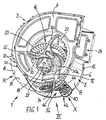
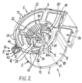
- FIGS. 1 and 2 respectively, has an inventive radial fan 1 a spiral housing. 2 on, which consists of two axially opposite, frontal Side parts 4, 6 and a connecting them, accordingly the spiral shape of the housing 2 in the circumferential direction curved housing shell 8 is made.
- the preferred Embodiment consists of the housing shell 8 Sheet metal, while the side panels 4, 6 as plastic molded parts are executed.
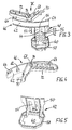
- each side part 4, 6 a the edge of the housing shell 8 cross web 10 and is about snap hooks 12 (see Fig. 6), the in corresponding openings 14 (see Fig. 1) of the housing shell 8 intervene, fixed.
- a fan / motor unit 16 is housed, wherein an electric motor 18, usually an external rotor motor, a radial impeller 20 carries.
- the radial fan 1 designed in one-sided or double-sided suction design be at least one of the two side parts, as shown at least the side part 4, an axial Inlet opening 22 has.
- the housing 2 has due its spiral shape a radial or more tangential outflow 24th
- the electric motor 18 is within the housing 2 via a Unsigned axis supported, each end of the Axis in a central support element 26 of the respective Side part 4 and 6 is held, preferably via elastic vibration isolation means 28, as in DE-GM 297 06 216 of the applicant are described, whereupon is fully referenced at this point.
- the respective carrier element 26 is over substantially radially and preferably curved extending struts 30 with the rest, the inflow opening 22 enclosing area the side part 4 or 6 connected. It is at least one of the aspirations, cf. in Fig. 6, the strut 30a, for formation a duct 32 with a U-shaped, in the direction the electric motor 18 formed open towards cross-section.
- the duct 32 serves to receive motor cables 34 (see Fig. 1), starting from the electric motor 18 over the region of the support member 26 and through the Conduit 32 of the strut 30a to a arranged on the housing 2 Connecting device 36 are guided.
- the connecting device 36 from an already connected to the motor lines 34 (pre-assembled) Connector part 40 and from a connector part 40 haltemden Mounting part 42 is.
- the mounting part 42 according to the invention via a Latching 44 releasably attachable to the housing 2.
- the connector part 40 may be an unillustrated, complementary, with external leads connected connector part are plugged.
- the Connector part 40 a plurality of individual connector elements (connector pins and / or sockets).
- the mounting member 42 is according to the invention optionally to each one of several different attachment points X on the housing 2 fastened.
- illustrated embodiment is an attachment to three different Fixing points X possible. Reference is made to FIGS. 1, 2 and 6 for this purpose.
- the mounting part 42 is in each case in the connection region between the housing jacket 6 and the side part 4 can be fastened, ie in the peripheral end region of the Housing jacket 8. Depending on the attachment point X, the mounting part is fastened 42 either indirectly via an additional fastener 46 or directly on the side part 4.
- the Mounting parts 42 holding means 48 are for holding the Mounting parts 42 holding means 48, in particular in the form of a slide-in receptacle for Insertion of a holding portion 50 of the mounting member 42 in the manner of a tongue and groove connection intended.
- the insertion receptacle formed by two lateral webs 52, between which the holding portion 50 in particular in axial direction can be inserted.
- the mounting part 42 at least one elastic latching arm 54, the with a latching nose 54a (FIG. 5) a holding edge 56 in such a way engages that the mounting member 42 thereby pulling against is releasably locked from the insertion receptacle.
- attachment point X are the holding means 48 and the Retaining edge 56 on the additional fastening element 46th or directly to the side part 4, namely at the Bridge 10, formed.
- Fig. 3 and 5 has the mounting part 42 a support portion 58 for the connector part 40, wherein this support section 58 starting from the approximately axially oriented, wall-like Holding portion 50, preferably in an approximately vertical plane lying about the axis of rotation of the fan approximately radially from the housing 2 extends away to the outside. It has the Carrier portion 58 adapted to the connector part 40 Retention 60 on.
- the connector part 40 not shown locking means in the Retainer 60 releasably fixed.
- the holding receptacle 60 is adapted to the respective connector part 40. This means, that by different design of the holding receptacle 60 almost any connector parts 40 is provided could be.
- fastener 46 is preferably attached to the housing 2, by first placed on the edge of the housing shell 8 and then fixed by the patch side part 4 becomes.
- the fastening element 46 a to the Curvature of the housing shell 8 adapted retaining web 62 on wherein on this holding web 62 on the one hand hook elements 64 for reaching over the housing shell 8 and preferably on the other at least one further hook element 66 for engagement in an opening spaced from the outer edge (not shown) of the housing shell 8 are arranged (in particular Fig. 4).
- joins the - radially outside the holding means 48 for the mounting part 42 having - retaining web 62 is an approximately radially inward pointing channel section 68, leading to the leading the motor leads 34 is used.
- the channel section 68 is preferably with at least one foldable closure flap 70 equipped with the motor lines 34 in the channel section 68 can be fixed. It has the Channel section 68 is a U-shaped, axially outward, i. away from the electric motor 18, open cross section.
- branches of the channel portion 68 branches of the channel portion 68, a housing-like receiving part 72nd which in particular for receiving a not shown electrical fuse element is used.
- the fastener 46 is also so in one place mountable relative to the side part 4 that its channel portion 68 in the direction of the motor lines 34th directly into the duct 32 of the strut 30a of the side part 4 passes.
- the side part 4 in this case has an integrated Cover member 76 for covering the fastener 46 and thereby closing the channel section 68 and the receiving part 72nd
- the side part 4 in Peripheral area between the position of the fastening element 46 and each further attachment point X for the Mounting part 42 and the connector part 40 tonesfixieriana 78, with which of the connector part 40 leading to the electric motor 18 motor lines 34 in their area between the connector element 40 and the Fixing element 46 fixed and in particular also at least can be covered in some areas to the outside.
- the connector part 40 for example, because of space problems at the site to arrange elsewhere on the radial fan 1, so are this for example, two more attachment points X provided. These are the Motor lines 34 executed with appropriate length.
- the mounting member 42 at the desired location X directly to the Side part 4 attached.
- the motor leads 34 are then in the Kirsfixierieri 78th insertable and so fixable.
- the integrated Dekelelement 76 of the side part 4 surrounds with margins slightly the fuse-receiving part 72, whereby vorteithaft note a spatial separation of air guide part in the interior of the radial fan 1 and Fuse receiving part 72 is carried out. It is of particular advantage that the motor cables 34 need not be threaded through openings at any point. Rather, it is done the assembly alone by plugging or plugging the individual modules.
Landscapes
- Engineering & Computer Science (AREA)
- Mechanical Engineering (AREA)
- General Engineering & Computer Science (AREA)
- Physics & Mathematics (AREA)
- Thermal Sciences (AREA)
- Structures Of Non-Positive Displacement Pumps (AREA)
- Motor Or Generator Frames (AREA)
- Coupling Device And Connection With Printed Circuit (AREA)
- Connection Of Motors, Electrical Generators, Mechanical Devices, And The Like (AREA)
- External Artificial Organs (AREA)
Description
- Fig. 1
- eine Perspektivansicht eines erfindungsgemäßen Radialgebläses in einem Zustand mit einem noch etwas geöffneten Seitenteil,
- Fig. 2
- eine Perspektivansicht wie in Fig. 1 im fertig montierten Zustand, jedoch mit einer beispielhaften Alternativanordnung eines erfindungsgemäßen Steckverbinderteils,
- Fig. 3
- eine vergrößerte Detailansicht der Anschlußeinrichtung nach der Erfindung (Pfeilrichtung III gemäß Fig. 1),
- Fig. 4
- eine Darstellung eines Befestigungselementes aus einer gegenüberliegenden Blickrichtung (Pfeil IV in Fig. 3),
- Fig. 5
- eine Detailansicht eines erfindungsgemäßen Montageteils und
- Fig. 6
- eine Ansicht auf die Innenseite des Gehäuse-Seitenteils nach Fig. 1.
Claims (14)
- Radialgebläse (1) mit einem Gehäuse (2) zur Aufnahme einer Lüfterrad-Motor-Einheit (16), wobei das Gehäuse (2) zwei Seitenteile (4, 6) und einen diese verbindenden Gehäusemantel (8) aufweist, und mit einer Anschlusseinrichtung (36) zum elektrischen Verbinden von Motorleitungen (34) mit äusseren Anschlussleitungen,
dadurch gekennzeichnet, dass
die Anschlusseinrichtung (36) aus einem mit den Motorleitungen (34) verbundenen Steckverbinderteil (40) zum Steckverbinden mit einem komplementären, mit den Anschlussleitungen verbundenen Verbinderteil sowie aus einem das Steckverbinderteil (40) halternden Montageteil (42) besteht, wobei das Montageteil (42) wahlweise an einer von mehreren unterschiedlichen Befestigungsstellen (X) im Verbindungsbereich zwischen dem Gehäusemantel (8) und einem der beiden Seitenteile (4) über eine Rastverbindung (44) lösbar an dem Gehäuse (2) befestigbar ist. - Radialgebläse nach Anspruch 1,
dadurch gekennzeichnet, daß das Montageteil (42) einerseits mittelbar über ein zusätzliches Befestigungselement (46) und/oder andererseits unmittelbar an dem Seitenteil (4) oder an dem Gehäusemantel (8) befestigbar ist. - Radialgebläse nach Anspruch 2,
dadurch gekennzeichnet, daß das Seitenteil (4) und/oder das zusätzliche Befestigungselement (46) an der jeweiligen Befestigungsstelle (X) Haltemittel (48) insbesondere in Form einer Einschubaufnahme zum Einschieben eines Halteabschnittes (50) des Montageteils (42) aufweisen/aufweist. - Radialgebläse nach Anspruch 3,
dadurch gekennzeichnet, daß die Haltemittel (48) derart ausgebildet sind, daß das Montageteil (42) insbesondere parallel zur Lüfter-Drehachse einschiebbar ist, wobei das Montageteil (42) mindestens einen elastischen Rastarm (54) aufweist, der mit einer Rastnase (54a) eine Haltekante (56) des Seitenteils (4) bzw. des Befestigungselementes (46) derart untergreift, daß das Montageteil (42) gegen Herausziehen aus der Einschubaufnahme lösbar arretiert ist. - Radialgebläse nach Anspruch 3 oder 4,
dadurch gekennzeichnet, daß das Montageteil (42) einen Trägerabschnitt (58) für das Steckverbinderteil (40) aufweist, wobei sich der Trägerabschnitt (58) ausgehend von dem Halteabschnitt (50) vorzugsweise in einer etwa senkrecht zur Drehachse liegenden Ebene etwa radial von dem Gehäuse (2) weg erstreckt. - Radialgebläse nach Anspruch 5,
dadurch gekennzeichnet, daß der Trägerabschnitt (58) eine an das Steckverbinderteil (40) angepaßte Halteaufnahme (60) aulweist, und daß das Steckverbinderteil (40) über Rastmittel in der Halteaufnahme (60) fixiert wird. - Radialgebläse nach einem der Ansprüche 2 bis 6,
dadurch gekennzeichnet, daß das zusätzliche Befestigungselement (46) auf den Rand des Gehäusemantels (8) aufsetzbar ist und durch das dann aufgesetzte Seitenteil (4) fixiert wird. - Radialgebläse nach einem der Ansprüche 2 bis 7,
dadurch gekennzeichnet, daß das Befestigungselement (46) einen an die Krümmung des Gehäusemantels (8) angepaßten Haltesteg (62) aufweist, wobei an dem Haltesteg (62) einerseits Hakenelemente (64) zum Übergreifen des Gehäusemantels (8) und vorzugsweise andererseits mindestens ein Hakeneiement (66) zum Eingreifen in eine vom Außenrand beabstandete Öffnung des Gehäusemantels (8) angeordnet sind. - Radialgebläse nach Anspruch 8,
dadurch gekennzeichnet, daß sich an den - radial außenseitig die Haltemittel (48) für das Montageteil (42) aufweisenden - Haltesteg (62) ein etwa radial nach innen weisender Kanalabschnitt (68) zur führenden Aufnahme der Motorleitungen (34) anschließt. - Radialgebläse nach Anspruch 9,
dadurch gekennzeichnet, daß von dem Kanalabschnitt (68) ein gehäuseartiges Aufnahmeteil (72) - insbesondere für ein elektrisches Sicherungselement - mit entsprechenden Leitungsdurchführöffnungen (74) abzweigt. - Radialgebläse nach einem der Ansprüche 1 bis 10,
dadurch gekennzeichnet, daß das Gehäuse-Seitenteil (4,6) eine axiale Einströmöffnung (22) und in diesem Bereich ein zentrisches Motor-Trägerelement (26) aufweist, das über im wesentlichen radial und vorzugsweise gekrümmt verlaufende Streben (30) mit dem übrigen, die Einströmöffnung (22) umschließenden Bereich des Seitenteils (4,6) verbunden ist, wobei zumindest eine (30a) der Streben (30) zur Bildung eines Leitungskanals (32) mit einem U-förmigen, zur Motorseite hin offenen Querschnitt ausgebildet ist. - Radialgebläse nach Anspruch 11 und nach Anspruch 9 oder 10,
dadurch gekennzeichnet, daß das Befestigungselement (46) derart an einer der Befestigungsstellen relativ zu dem Seitenteil (4) montierbar ist, daß sein Kanalabschnitt (68) in Verlaufsrichtung der Motorleitungen (34) in den Leitungskanal (32) des Seitenteils (4) übergeht. - Radialgebläse nach einem der Ansprüche 9 bis 12,
dadurch gekennzeichnet, daß das Seitenteil (4) ein integriertes Deckelelement (76) zum Abdecken des Befestigungselementes (46) und zum Verschließen des Kanalabschnittes (68) und/oder des Aufnahmeteils (72) aufweist. - Radialgebläse nach einem der Ansprüche 2 bis 13,
dadurch gekennzeichnet, daß das Seitenteil (4) im Umfangsbereich zwischen der Befestigungsstelle des Befestigungselementes (46) und der/ jeder weiteren Befestigungsstelle (X) für das Montageteil (42) Leitungsfixierelemente (78) für die von dem Steckverbinderteil (40) zum Motor führenden Motorleitungen (34) aufweist.
Applications Claiming Priority (2)
| Application Number | Priority Date | Filing Date | Title |
|---|---|---|---|
| DE29819962U DE29819962U1 (de) | 1998-11-09 | 1998-11-09 | Radialgebläse mit Anschluß-Steckverbindung |
| DE29819962U | 1998-11-09 |
Publications (2)
| Publication Number | Publication Date |
|---|---|
| EP1000783A1 EP1000783A1 (de) | 2000-05-17 |
| EP1000783B1 true EP1000783B1 (de) | 2003-08-20 |
Family
ID=8065049
Family Applications (1)
| Application Number | Title | Priority Date | Filing Date |
|---|---|---|---|
| EP99119853A Expired - Lifetime EP1000783B1 (de) | 1998-11-09 | 1999-10-07 | Radialgebläse mit Anschluss-Steckverbindung |
Country Status (7)
| Country | Link |
|---|---|
| EP (1) | EP1000783B1 (de) |
| KR (1) | KR100365361B1 (de) |
| AT (1) | ATE247565T1 (de) |
| DE (2) | DE29819962U1 (de) |
| DK (1) | DK1000783T3 (de) |
| ES (1) | ES2205668T3 (de) |
| PT (1) | PT1000783E (de) |
Families Citing this family (10)
| Publication number | Priority date | Publication date | Assignee | Title |
|---|---|---|---|---|
| US6864653B2 (en) | 2001-11-26 | 2005-03-08 | Ebm-Papst St. Georgen Gmbh & Co. Kg | Equipment fan |
| DE10253227A1 (de) * | 2002-11-15 | 2004-05-27 | Papst-Motoren Gmbh & Co. Kg | Lüfter, insbesondere Gerätelüfter |
| DE102005017266A1 (de) | 2005-04-14 | 2006-10-19 | Robert Bosch Gmbh | Elektronikmodul für einen Lüfter einer Verbrennungskraftmaschine eines Kraftfahrzeugs |
| DE102012106529A1 (de) * | 2012-07-18 | 2014-01-23 | Ebm-Papst St. Georgen Gmbh & Co. Kg | Lüfter mit Lüftergehäuse |
| ITBO20120499A1 (it) * | 2012-09-20 | 2014-03-21 | Spal Automotive Srl | Unita' di ventilazione. |
| DE102013204136A1 (de) * | 2013-03-11 | 2014-09-11 | BSH Bosch und Siemens Hausgeräte GmbH | Motoraufhängung für einen Gebläsemotor eines Radialgebläses einer Dunstabzugshaube |
| DE102015213470B4 (de) | 2015-07-17 | 2025-07-10 | Werkhaus GmbH & Co. KG | Lüfterbaustein |
| DE102015017552B4 (de) * | 2015-07-17 | 2025-08-21 | Werkhaus GmbH & Co. KG | Kochfeld-System mit Lüfterbaustein |
| DE102016105655A1 (de) | 2016-03-29 | 2017-10-05 | Minebea Co., Ltd. | Radialventilator und Verfahren zur Herstellung eines Radialventilators |
| CN208634070U (zh) * | 2018-06-05 | 2019-03-22 | 中山大洋电机股份有限公司 | 一种离心风机组件及应用其的离心风机 |
Family Cites Families (4)
| Publication number | Priority date | Publication date | Assignee | Title |
|---|---|---|---|---|
| JP2858368B2 (ja) * | 1990-08-29 | 1999-02-17 | 松下電器産業株式会社 | 無整流子直流軸流ファンモータ |
| FR2708056B1 (fr) * | 1993-07-22 | 1995-08-25 | Valeo Thermique Habitacle | Dispositif d'encliquetage, et ensemble ainsi équipé, notamment dans une unité de ventilation, chauffage et/ou climatisation pour automobile. |
| FR2761545A1 (fr) * | 1997-03-27 | 1998-10-02 | Valeo Systemes Dessuyage | Motoventilateur pour vehicule automobile avec connecteur vers le vehicule |
| DE29706216U1 (de) | 1997-04-08 | 1998-08-06 | ebm Werke GmbH & Co., 74673 Mulfingen | Anordnung zur schwingungsisolierenden Aufhängung eines Elektromotors |
-
1998
- 1998-11-09 DE DE29819962U patent/DE29819962U1/de not_active Expired - Lifetime
-
1999
- 1999-10-07 AT AT99119853T patent/ATE247565T1/de not_active IP Right Cessation
- 1999-10-07 DK DK99119853T patent/DK1000783T3/da active
- 1999-10-07 EP EP99119853A patent/EP1000783B1/de not_active Expired - Lifetime
- 1999-10-07 ES ES99119853T patent/ES2205668T3/es not_active Expired - Lifetime
- 1999-10-07 DE DE59906659T patent/DE59906659D1/de not_active Expired - Lifetime
- 1999-10-07 PT PT99119853T patent/PT1000783E/pt unknown
- 1999-11-03 KR KR1019990048347A patent/KR100365361B1/ko not_active Expired - Fee Related
Also Published As
| Publication number | Publication date |
|---|---|
| ATE247565T1 (de) | 2003-09-15 |
| EP1000783A1 (de) | 2000-05-17 |
| KR100365361B1 (ko) | 2002-12-18 |
| DE59906659D1 (de) | 2003-09-25 |
| PT1000783E (pt) | 2003-11-28 |
| ES2205668T3 (es) | 2004-05-01 |
| DK1000783T3 (da) | 2003-12-08 |
| KR20000035206A (ko) | 2000-06-26 |
| DE29819962U1 (de) | 2000-03-23 |
Similar Documents
| Publication | Publication Date | Title |
|---|---|---|
| DE19950245C1 (de) | Radialgebläse | |
| DE3880470T2 (de) | Armatur fuer treibhausbeleuchtung. | |
| EP2952368B1 (de) | Anhängekupplung | |
| DE10253227A1 (de) | Lüfter, insbesondere Gerätelüfter | |
| DE20308886U1 (de) | Doppel-Gebläseanordnung | |
| DE19841762A1 (de) | Gebläsegehäuse und Radialgebläse | |
| EP1000783A1 (de) | Radialgebläse mit Anschluss-Steckverbindung | |
| EP0917276A1 (de) | Statorgehäuse für Elektromotoren | |
| DE102008023311A1 (de) | Umluftweiche sowie Verfahren zum Montieren einer Umluftweiche | |
| EP1119087B1 (de) | Geräteeinbaudose für Leitungsführungskanäle | |
| DE10259761A1 (de) | Lüftergehäuse | |
| DE102010042097A1 (de) | Getriebegehäuse, Motorgetriebeanordnung und Scheibenwischerantrieb | |
| DE102008036936B4 (de) | Verfahren zur Montage einer Langfeldleuchte | |
| EP0818073A1 (de) | Sammelschienensystem | |
| DE8626016U1 (de) | Halterung zum Halten eines Gebläses in einem Gehäuse | |
| DE3784089T2 (de) | Beleuchtungssystem mit mehreren beleuchtungseinheiten. | |
| DE4240381A1 (de) | Elektromotor, insbesondere Kommutatormotor | |
| DE60308458T2 (de) | Installationsdose für elektrische Geräte | |
| DE202006006183U1 (de) | Möbel | |
| EP3795388B1 (de) | Adapter mit einem stecker für eine 12 v- oder 24 v-anhängersteckdose und mit einer 24 v- oder 12 v-anhängersteckdose | |
| DE19814108B4 (de) | Elektrischer Steckverbinder zur Montage in einem Ausschnitt in einer Wandung | |
| DE9314551U1 (de) | Anordnung an vorkonfektionierten elektrischen Gerätedosen für deren unmittelbaren Einbau in Installationskanäle | |
| DE10008063C2 (de) | Antennenanordnung | |
| EP0833411B1 (de) | Elektrischer Steckverbinder | |
| DE60201787T2 (de) | Schutz- und Ankerabdeckung für elektrische Kondensatoren |
Legal Events
| Date | Code | Title | Description |
|---|---|---|---|
| PUAI | Public reference made under article 153(3) epc to a published international application that has entered the european phase |
Free format text: ORIGINAL CODE: 0009012 |
|
| AK | Designated contracting states |
Kind code of ref document: A1 Designated state(s): AT BE CH CY DE DK ES FI FR GB GR IE IT LI LU MC NL PT SE |
|
| AX | Request for extension of the european patent |
Free format text: AL;LT;LV;MK;RO;SI |
|
| 17P | Request for examination filed |
Effective date: 20000824 |
|
| AKX | Designation fees paid |
Free format text: AT BE CH CY DE DK ES FI FR GB GR IE IT LI LU MC NL PT SE |
|
| 17Q | First examination report despatched |
Effective date: 20020729 |
|
| RAP1 | Party data changed (applicant data changed or rights of an application transferred) |
Owner name: EBM WERKE GMBH & CO. KG |
|
| GRAH | Despatch of communication of intention to grant a patent |
Free format text: ORIGINAL CODE: EPIDOS IGRA |
|
| GRAS | Grant fee paid |
Free format text: ORIGINAL CODE: EPIDOSNIGR3 |
|
| GRAA | (expected) grant |
Free format text: ORIGINAL CODE: 0009210 |
|
| REG | Reference to a national code |
Ref country code: SE Ref legal event code: TRGR |
|
| AK | Designated contracting states |
Designated state(s): AT BE CH CY DE DK ES FI FR GB GR IE IT LI LU MC NL PT SE |
|
| PG25 | Lapsed in a contracting state [announced via postgrant information from national office to epo] |
Ref country code: IE Free format text: LAPSE BECAUSE OF FAILURE TO SUBMIT A TRANSLATION OF THE DESCRIPTION OR TO PAY THE FEE WITHIN THE PRESCRIBED TIME-LIMIT Effective date: 20030820 |
|
| REG | Reference to a national code |
Ref country code: GB Ref legal event code: FG4D Free format text: NOT ENGLISH |
|
| REG | Reference to a national code |
Ref country code: CH Ref legal event code: EP |
|
| GBT | Gb: translation of ep patent filed (gb section 77(6)(a)/1977) | ||
| REG | Reference to a national code |
Ref country code: IE Ref legal event code: FG4D Free format text: GERMAN |
|
| REG | Reference to a national code |
Ref country code: GR Ref legal event code: EP Ref document number: 20030403224 Country of ref document: GR |
|
| REF | Corresponds to: |
Ref document number: 59906659 Country of ref document: DE Date of ref document: 20030925 Kind code of ref document: P |
|
| PG25 | Lapsed in a contracting state [announced via postgrant information from national office to epo] |
Ref country code: LU Free format text: LAPSE BECAUSE OF NON-PAYMENT OF DUE FEES Effective date: 20031007 Ref country code: CY Free format text: LAPSE BECAUSE OF FAILURE TO SUBMIT A TRANSLATION OF THE DESCRIPTION OR TO PAY THE FEE WITHIN THE PRESCRIBED TIME-LIMIT Effective date: 20031007 Ref country code: AT Free format text: LAPSE BECAUSE OF NON-PAYMENT OF DUE FEES Effective date: 20031007 |
|
| PG25 | Lapsed in a contracting state [announced via postgrant information from national office to epo] |
Ref country code: MC Free format text: LAPSE BECAUSE OF NON-PAYMENT OF DUE FEES Effective date: 20031031 Ref country code: LI Free format text: LAPSE BECAUSE OF NON-PAYMENT OF DUE FEES Effective date: 20031031 Ref country code: CH Free format text: LAPSE BECAUSE OF NON-PAYMENT OF DUE FEES Effective date: 20031031 Ref country code: BE Free format text: LAPSE BECAUSE OF NON-PAYMENT OF DUE FEES Effective date: 20031031 |
|
| REG | Reference to a national code |
Ref country code: DK Ref legal event code: T3 |
|
| REG | Reference to a national code |
Ref country code: IE Ref legal event code: FD4D |
|
| ET | Fr: translation filed | ||
| BERE | Be: lapsed |
Owner name: *EBM WERKE G.M.B.H. & CO. K.G. Effective date: 20031031 |
|
| REG | Reference to a national code |
Ref country code: ES Ref legal event code: FG2A Ref document number: 2205668 Country of ref document: ES Kind code of ref document: T3 |
|
| REG | Reference to a national code |
Ref country code: CH Ref legal event code: PL |
|
| PLBE | No opposition filed within time limit |
Free format text: ORIGINAL CODE: 0009261 |
|
| STAA | Information on the status of an ep patent application or granted ep patent |
Free format text: STATUS: NO OPPOSITION FILED WITHIN TIME LIMIT |
|
| 26N | No opposition filed |
Effective date: 20040524 |
|
| REG | Reference to a national code |
Ref country code: FR Ref legal event code: PLFP Year of fee payment: 17 |
|
| REG | Reference to a national code |
Ref country code: FR Ref legal event code: PLFP Year of fee payment: 18 |
|
| REG | Reference to a national code |
Ref country code: FR Ref legal event code: PLFP Year of fee payment: 19 |
|
| PGFP | Annual fee paid to national office [announced via postgrant information from national office to epo] |
Ref country code: PT Payment date: 20170926 Year of fee payment: 19 |
|
| PGFP | Annual fee paid to national office [announced via postgrant information from national office to epo] |
Ref country code: FR Payment date: 20171023 Year of fee payment: 19 Ref country code: DK Payment date: 20171024 Year of fee payment: 19 Ref country code: FI Payment date: 20171018 Year of fee payment: 19 Ref country code: DE Payment date: 20171023 Year of fee payment: 19 |
|
| PGFP | Annual fee paid to national office [announced via postgrant information from national office to epo] |
Ref country code: SE Payment date: 20171024 Year of fee payment: 19 Ref country code: IT Payment date: 20171020 Year of fee payment: 19 Ref country code: ES Payment date: 20171103 Year of fee payment: 19 Ref country code: GR Payment date: 20171026 Year of fee payment: 19 Ref country code: NL Payment date: 20171023 Year of fee payment: 19 Ref country code: GB Payment date: 20171024 Year of fee payment: 19 |
|
| REG | Reference to a national code |
Ref country code: DE Ref legal event code: R082 Ref document number: 59906659 Country of ref document: DE Representative=s name: PATENTANWAELTE STAEGER & SPERLING PARTNERSCHAF, DE |
|
| REG | Reference to a national code |
Ref country code: DE Ref legal event code: R119 Ref document number: 59906659 Country of ref document: DE |
|
| REG | Reference to a national code |
Ref country code: DK Ref legal event code: EBP Effective date: 20181031 |
|
| REG | Reference to a national code |
Ref country code: SE Ref legal event code: EUG |
|
| REG | Reference to a national code |
Ref country code: NL Ref legal event code: MM Effective date: 20181101 |
|
| GBPC | Gb: european patent ceased through non-payment of renewal fee |
Effective date: 20181007 |
|
| PG25 | Lapsed in a contracting state [announced via postgrant information from national office to epo] |
Ref country code: FI Free format text: LAPSE BECAUSE OF NON-PAYMENT OF DUE FEES Effective date: 20181007 Ref country code: NL Free format text: LAPSE BECAUSE OF NON-PAYMENT OF DUE FEES Effective date: 20181101 Ref country code: PT Free format text: LAPSE BECAUSE OF NON-PAYMENT OF DUE FEES Effective date: 20190408 Ref country code: DE Free format text: LAPSE BECAUSE OF NON-PAYMENT OF DUE FEES Effective date: 20190501 Ref country code: SE Free format text: LAPSE BECAUSE OF NON-PAYMENT OF DUE FEES Effective date: 20181008 |
|
| PG25 | Lapsed in a contracting state [announced via postgrant information from national office to epo] |
Ref country code: FR Free format text: LAPSE BECAUSE OF NON-PAYMENT OF DUE FEES Effective date: 20181031 Ref country code: GR Free format text: LAPSE BECAUSE OF NON-PAYMENT OF DUE FEES Effective date: 20190506 |
|
| PG25 | Lapsed in a contracting state [announced via postgrant information from national office to epo] |
Ref country code: GB Free format text: LAPSE BECAUSE OF NON-PAYMENT OF DUE FEES Effective date: 20181007 Ref country code: IT Free format text: LAPSE BECAUSE OF NON-PAYMENT OF DUE FEES Effective date: 20181007 Ref country code: DK Free format text: LAPSE BECAUSE OF NON-PAYMENT OF DUE FEES Effective date: 20181031 |
|
| REG | Reference to a national code |
Ref country code: ES Ref legal event code: FD2A Effective date: 20191129 |
|
| PG25 | Lapsed in a contracting state [announced via postgrant information from national office to epo] |
Ref country code: PT Free format text: LAPSE BECAUSE OF EXPIRATION OF PROTECTION Effective date: 20191017 |
|
| PG25 | Lapsed in a contracting state [announced via postgrant information from national office to epo] |
Ref country code: ES Free format text: LAPSE BECAUSE OF NON-PAYMENT OF DUE FEES Effective date: 20181008 |