EP1000287B1 - Accouplement a verrouillage de surete - Google Patents
Accouplement a verrouillage de surete Download PDFInfo
- Publication number
- EP1000287B1 EP1000287B1 EP98934537A EP98934537A EP1000287B1 EP 1000287 B1 EP1000287 B1 EP 1000287B1 EP 98934537 A EP98934537 A EP 98934537A EP 98934537 A EP98934537 A EP 98934537A EP 1000287 B1 EP1000287 B1 EP 1000287B1
- Authority
- EP
- European Patent Office
- Prior art keywords
- pivotal
- cam arm
- pull ring
- cam
- coupling unit
- Prior art date
- Legal status (The legal status is an assumption and is not a legal conclusion. Google has not performed a legal analysis and makes no representation as to the accuracy of the status listed.)
- Expired - Lifetime
Links
Images


Classifications
-
- F—MECHANICAL ENGINEERING; LIGHTING; HEATING; WEAPONS; BLASTING
- F16—ENGINEERING ELEMENTS AND UNITS; GENERAL MEASURES FOR PRODUCING AND MAINTAINING EFFECTIVE FUNCTIONING OF MACHINES OR INSTALLATIONS; THERMAL INSULATION IN GENERAL
- F16L—PIPES; JOINTS OR FITTINGS FOR PIPES; SUPPORTS FOR PIPES, CABLES OR PROTECTIVE TUBING; MEANS FOR THERMAL INSULATION IN GENERAL
- F16L37/00—Couplings of the quick-acting type
- F16L37/08—Couplings of the quick-acting type in which the connection between abutting or axially overlapping ends is maintained by locking members
- F16L37/12—Couplings of the quick-acting type in which the connection between abutting or axially overlapping ends is maintained by locking members using hooks, pawls or other movable or insertable locking members
- F16L37/18—Joints tightened by eccentrics or rotatable cams
Definitions
- the present invention relates, in general, to couplings for connecting hoses and other conduits which carry fluids and, in particular, to a fluid coupling having a safety latching mechanism which can be operated to quickly connect and disconnect hoses and other conduits.
- Couplings for connecting hoses and other conduits which carry fluids have been in use for many years.
- One common form of such couplings often referred to as cam and groove couplings or cam-lock couplings or cam locking quick-disconnect couplings, includes a female coupling unit on which a pair of cam arms are pivotally mounted in openings extending through the wall of the female coupling unit to the bore of the female coupling member and a male coupling unit, having a groove in an outside surface, is received in the bore of female coupling unit and is engaged by the cam arms in the groove of the male coupling unit to fix the male coupling unit in the female coupling unit.
- the cam arms are pivoted radially outward providing clearance for the male coupling unit to be inserted.
- the cam arms are pivoted inward drawing the male coupling unit into the bore of the female coupling unit to fix the male coupling unit in place while compressing a compressible sealing ring carried in a groove in the bore in the female coupling unit.
- the cam arms on the female coupling unit are pivoted outwardly to free the male coupling unit and permit removal of the male coupling unit.
- Padlocks have been added to the couplings to protect against both unintentional and unauthorized disconnection of the coupling. Typically, the arrangements which have included a padlock have not been sufficiently effective in providing the desired protection.
- GB-A- 2 102 520 discloses a quick disconnect cam and groove coupling.
- the cam arm is prevented from rotating by a locking pin that is inserted into a lug that extends through the cam arm body.
- EP-A- 742 402 also discloses a cam and groove coupling.
- the cam arm is prevented from rotation by a locking pin that is inserted into a groove located beneath the cam arm.
- the locking pin is manipulated by pulling on the pull ring attached at the free end of the cam arm.
- a safety locking coupling assembly constructed in accordance with the present invention, includes a generally cylindrical male coupling unit and a female coupling unit which includes a generally cylindrical body, a cam arm mounted to the body of the female coupling unit, and a pull ring carried by the cam arm.
- the body of the female coupling unit has an inside wall defining a bore which extends axially of the body between first and second end faces of the body and within which the male coupling unit is fitted from said first end face of said body.
- the body also has an opening extending through the body and first and second ears projecting from an outside wall of body at opposite sides of the opening in the body.
- the cam arm is mounted to the body of the female coupling unit at the opening in body for pivotal movement relative to the body between a first pivotal locked position and a second pivotal released position.
- the cam arm has a cam surface projecting from within the opening in the body into the bore in the body and engaging the male coupling unit received by the bore in the body when the cam arm is in the first pivotal locked position and retracted into the first opening in the body from the bore in the body and disengaged from the male coupling unit received by the bore in the body when the cam arm is in the second pivotal released position.
- the cam arm also has an arm portion having a through hole extending through the width thereof at a free end of the arm portion.
- the pull ring extends through the through hole in the arm portion of the cam arm for pivotal movement of the pull ring relative to the cam arm between a first pivotal locked position and a second pivotal released position for moving the cam arms from the first pivotal locked positions of the cam arm to the second pivotal released positions of the cam arm.
- the pull ring abuts against the first and the second ears on the body of the female coupling unit upon pivotal movement of the cam arm from the first pivotal locked position of the cam arm toward the second pivotal released position of the cam arm while the pull ring is in the first pivotal locked position of the pull ring to prevent pivotal movement of the cam arm to the second pivotal released position of the cam arm and free of the first and the second cars upon pivotal movement of the pull ring from the first pivotal locked position of the pull ring to the second pivotal released position of the pull ring to permit pivotal movement of the cam arm to the second pivotal released position of the cam arm.
- Another aspect of the present invention which is described below is the manner in which the cam arm and the means by which the cam arm is mounted to the body of the female coupling unit are arranged to receive a padlock. whereby the safety locking coupling assembly is protected against tampering to a greater extent than prior art arrangements.
- Yet a further aspect of the present invention is the configuration of the cam surface of the cam arm, whereby the cam arm is strengthened.
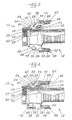
- a safety locking coupling assembly constructed in accordance with the present invention, includes a generally cylindrical male coupling unit 10 and a female coupling unit 12 which includes a generally cylindrical body 14 having an inside wall 15 defining a bore which extends axially of body 14 between first and second end faces 16 and 17 of body 14.
- Male coupling unit 10 is fitted within the bore of body 14 of female coupling unit 12 from first end face 16 of body 14 .
- the opposite end of female coupling unit 12 for example arranged as a hose shank 18
- the opposite end of male coupling unit 10 for example having an internal thread 19 . are adapted for attachment to hoses or pipes.
- the bore in body 14 of female coupling unit 12 has a circumferential groove 21 in the inside wall of the body which is spaced from first end face 18 of the body.
- Female coupling unit 12 further includes a compressible sealing ring 22 positioned in circumferential groove 21 which extends into the bore beyond the inside wall of body 14.
- Male coupling unit 10 bears against sealing ring 22 tightly.
- a shoulder 25 of circumferential groove 21 in body 14 of female coupling unit 12 supports sealing ring 22 against axial movement.
- Male coupling unit 10 has a circumferential groove 23 in an outside surface.
- Body 14 of female coupling unit 10 also has first and second diametrically opposed openings 24 extending through the body. Only one such opening is shown in the drawings.
- First and second ears 26, shown most clearly in Figure 5, project from an outside wall of body 14 at opposite sides of first opening 24 in the body.
- First and second ears 26 have a sloped, arcade surface 28.
- Third and fourth ears 32 project from the outside wall of body 14 at opposite sides of second opening 24 in body 14 and are similar to first and second ears 26.
- Female coupling unit 12 also has first and second cam arms 36 and 38 mounted to body 14 at first and second openings 24 in body 14, respectively, for pivotal movement relative to body 14 between a first pivotal locked position as shown in Figures 4, 5 and 6 and a second pivotal released position as shown in Figure 1.
- First cam arm 36 is mounted to first and second ears 26 by a pivot pin 40 for pivotal movement between the first and the second ears.
- First cam arm 36 has a first cam surface 42 projecting from within first opening 24 in body 14 into the bore in body 14 and engaging male coupling unit 10 received by the bore in body 14 when first cam arm 36 is in the first pivotal locked position and retracted into first opening 24 in body 14 from bore in body 14 and disengaged from male coupling unit 10 received by the bore in body 14 when first cam arm 36 is in the second pivotal released position.
- First cam arm 36 also has a first arm portion 44 having a first through hole 46 extending through the width thereof at a free end of first arm portion 44.
- Second cam arm 38 is mounted to third and fourth ears 32 by a pivot pin 48 for pivotal movement between the third and the fourth ears.
- Second cam arm 38 is similar to first cam arm 36 having a second cam surface, not shown but similar to first cam surface 42, and a second arm portion 50.
- the second cam surface of second cam arm 38 projects from within the second opening in body 14 of female coupling unit 12 into the bore in body 14 and engages male coupling unit 10 unit received by the bore in body 14 when second cam arm 38 is in the first pivotal locked position and is retracted into the second opening in body 14 from the bore in body 14 and disengaged from male coupling unit 10 received by the bore in body 14 when second cam arm 38 is in the second pivotal released position.
- Second arm portion 50 has a second through hole 52 extending through the width thereof at a free end of second arm portion 50.
- Female coupling unit 12 also has first and second pull rings 54 and 56 extending, respectively, through first through hole 46 and second through hole 52 in first arm portion 44 and second arm portion 50 of first cam arm 36 and second cam arm 38 for pivotal movement of the first and the second pull rings relative to the first and the second cam arms, respectively.
- First and second pull rings 54 and 56 can undergo pivotal movement between a first pivotal locked position and a second pivotal released position for moving first cam arm 36 and second cam arm 38, respectively, from the first pivotal locked positions of the cam arms to the second pivotal released positions of the cam arms.
- Each pull ring 54 and 56 is a resilient circular multiple turn coil and each of the pull rings and each through hole 46 and 52 through which the pull rings extend are dimensioned to bias the pull rings into a position against the arm portions of the cam arms to which they are mounted in the first pivotal locked positions of the pull rings and to permit overcoming the bias and permit pivotal movement of the pull rings away from arm portions of cam arm to which they are mounted to the second pivotal released position of the pull rings when the pull rings are pulled toward the second pivotal released position of the pull rings.
- first pull ring 54 abuts against the sloped arcade surface 28 of first and second ears 26 upon pivotal movement of first cam arm 36 from the first pivotal locked position of the first cam arm toward the second pivotal released position of the first cam arm while the first pull ring is in the first pivotal locked position of the first pull ring to prevent pivotal movement of the first cam arm to the second pivotal released position of the first cam arm.
- First pull ring 54 is free of first and second ears 26 upon pivotal movement of the first pull ring from the first pivotal locked position of the first pull ring to said second pivotal released position of the first pull ring to permit pivotal movement of first cam arm 36 to the second pivotal released position of the first cam arm.
- Second pull ring 56 in cooperation with the sloped arcade surface 28 of third and fourth ears 32, effects locking and movement of second cam arm 38 in the same manner as first pull ring 54, in cooperation with first ears 26, effects locking and movement first cam arm 36.
- Male coupling unit 10 preferably has a tapered end 58 and female coupling unit 12 preferably has an annular end radius 60 which together ease insertion of the male coupling unit into female coupling unit 12 .
- An end face 62 of male coupling unit 10 is adapted to bear tightly against sealing ring 22 in female coupling unit 12.
- Cam surfaces 42 of first cam arm 36 and second cam arm 38 have a relief 64 which allows insertion of male coupling unit 10 into female coupling unit 12.
- Relief 64 of cam surfaces 42 is an arcade concave surface aligned with the axis of male coupling unit 10 and the axis of female coupling unit 12 when cam arms 36 and 38 are in the pivotal released positions of the cam arms as shown in Figure 1.
- the arcade nature of relief 64, shown in Figure 5, provides added material to the cam arms as they follow the shape of male member 10 and thereby strengthens the cams.
- cam surfaces 42 of cam arms 36 and 38 extend into and engage circumferential groove 23 in the outside surface of the male coupling unit when the cam arms are in the pivotal locked positions of the cam arms.
- cam surfaces 42 of the cam arms further engage groove 23 in the outside surface of male coupling unit 10 and draw the male coupling unit into female coupling unit 12 and compress sealing ring 22.
- pull rings 54 and 56 ride over first and second ears 26 and third and fourth ears 32, respectively, to snap against the associated ears.
- cam arms 36 and 38 have an enlarged pad area 66 which facilitates moving the cam arms into the pivotal locked positions of the cam arms by providing a comfortable surface for the hand or heal of the hand of an operator to the exert necessary force to lock the coupling assembly.
- cam arms 36 and 38 have extensions 67 and 68, respectively, beyond through holes 46 and 52, at the free ends of the arm portions of the cam arms.
- extensions 67 and 68 limit pivotal movement of pull rings 54 and 56 away from the first pivotal locked positions of the pull rings to the second pivotal released positions of the pull rings to prevent undesired distortion of the pull rings when the pull rings are pulled to disconnect the coupling assembly and prevent the pull rings from passing to beneath the cam arms.
- cam arms 36 and 38 have through holes 69 and 70, respectively, which are aligned with aligned through holes 71 and 72, respectively, in first and second ears 26 and third and fourth ears 32, respectively, when the cam arms are in the pivotal locked positions of the cam arms.
- a padlock 74 or similar device can be fitted through the aligned through holes to prevent further accidental opening of the coupling assembly or unauthorized opening of the coupling.
- a padlock if employed to lock the coupling assembly, first is removed. Next, the operator inserts a finger into each pull ring 54 and 56, as shown in Figure 6, to pull the pull rings from the pivotal locked positions of the pull rings to the pivotal released positions of the pull rings. Further pulling of the pull rings moves cam arms 36 and 38 from the pivotal locked positions of the cam arms to the pivotal released positions of the cam arms and withdraws cam surfaces 42 of the cam arms from groove 23 in the outside surface of male coupling unit 10.
- surfaces 76 of each cam arm 36 and 38 opposite from cam surfaces 42 are extended and act as a barrier to projections from the environment from accessing pull rings 54 and 56 unintentionally, as best shown in 5 Figure 4.
Landscapes
- Engineering & Computer Science (AREA)
- General Engineering & Computer Science (AREA)
- Mechanical Engineering (AREA)
- Quick-Acting Or Multi-Walled Pipe Joints (AREA)
- Buckles (AREA)
Claims (8)
- Unité de raccord femelle (12) comprenant :caractérisée par le fait que :un corps généralement cylindrique (14) comportant une paroi interne (15) définissant un alésage qui s'étend dans la direction axiale dudit corps (14) entre des première et deuxième faces terminales (16, 17) dudit corps (14), ledit alésage étant conçu pour recevoir une unité de raccord mâle (10) à ladite première face terminale (16) dudit corps (14) et ledit corps (14) comportant en outre une ouverture (24) s'étendant à travers ledit corps (14) ;un bras à came (36) monté sur ledit corps (14) à ladite ouverture (24) dans ledit corps (14) pour effectuer un mouvement pivotant par rapport audit corps (14) entre une première position dans laquelle le pivotement est verrouillé et une deuxième position dans laquelle le pivotement est libéré, et comportant :(a) une surface de came (42) :(1) faisant saillie à partir de l'intérieur de ladite ouverture (24) dans ledit corps (14) pour pénétrer dans ledit alésage dans ledit corps (14) et conçue pour entrer en contact avec une unité de raccord mâle logée dans ledit alésage dans ledit corps (14) lorsque ledit bras à came (36) se trouve dans ladite position dans laquelle le pivotement est verrouillé, et(2) rétractée dans ladite ouverture (24) dans ledit corps (14) à partir dudit alésage dans ledit corps (14) et conçue pour s'écarter d'une unité de raccord mâle (10) logée dans ledit alésage dans ledit corps (14) lorsque ledit bras à came (36) se trouve dans ladite deuxième position dans laquelle le pivotement est libéré, et(b) une portion de bras (44) possédant un trou traversant (46) s'étendant sur toute la largeur à une extrémité libre de ladite portion ; etune bride de raccord (54) s'étendant à travers ledit trou traversant (46) dans ladite portion de bras (44) dudit bras à came (36) pour faire pivoter ladite bride de raccord (54) par rapport audit bras à came (36) entre une première position dans laquelle le pivotement est verrouillé et une deuxième position dans laquelle le pivotement est libéré, afin de faire passer ledit bras à came (36) de ladite première position dudit bras à came (36) dans laquelle le pivotement est verrouillé à ladite deuxième position dudit bras à came (36) dans laquelle le pivotement est libéré ;(a) des première et deuxième oreilles (26) font saillie par rapport à la paroi externe dudit corps (14) sur les côtés opposés de ladite ouverture (24) dans ledit corps (14) ; et(b) ladite bride de raccord (54) :(1) vient buter contre lesdites première et deuxième oreilles (26) lors dudit mouvement pivotant dudit bras à came (36) entre ladite première position dudit bras à came (36) dans laquelle le pivotement est verrouillé et ladite deuxième position dudit bras à came (36) dans laquelle le pivotement est libéré, tandis que ladite bride de raccord (54) se trouve dans ladite première position de ladite bride de raccord (54) dans laquelle le pivotement est verrouillé pour empêcher le mouvement pivotant dudit bras à came (36) dans ladite deuxième position dudit bras à came (36) dans laquelle le pivotement est libéré, et(2) n'entre pas en contact avec lesdites première et deuxième oreilles (26) lors du mouvement pivotant de ladite bride de raccord (54) entre ladite première position de ladite bride de raccord (54) dans laquelle le pivotement est verrouillé et ladite deuxième position de ladite bride de raccord (54) dans laquelle le pivotement est libéré, pour permettre le mouvement pivotant dudit bras à came (36) dans ladite deuxième position dudit bras à came (36) dans laquelle le pivotement est libéré.
- Unité de raccord femelle (12) selon la revendication 1, caractérisée par le fait que ladite bride de raccord (54) est une bobine circulaire résiliente à multiples spires et ladite bride de raccord (54) et ledit trou traversant (46) à travers lequel s'étend ladite bride de raccord (54) sont dimensionnés de façon à :mettre ladite bride de raccord (54) en état de précontrainte dans une position contre ladite portion de bras (44) dudit bras à came (36) et dans ladite première position de ladite bride de raccord (54) dans laquelle le pivotement est verrouillé, etpermettre de vaincre ledit état de précontrainte et permettre le mouvement pivotant de ladite bride de raccord (54) à l'écart de ladite portion de bras (44) dudit bras à came (36) pour prendre ladite deuxième position de ladite bride de raccord (54) dans laquelle le pivotement est libéré, lorsque ladite bride de raccord (54) est tirée en direction de ladite deuxième position de ladite bride de raccord (54) dans laquelle le pivotement est libéré.
- Unité de raccord femelle (12) selon la revendication 1, ledit corps (14) comportant en outre une deuxième ouverture (24) diamétralement opposée, s'étendant à travers ledit corps (14),un deuxième bras à came (38) monté sur ledit corps (14) à ladite deuxième ouverture (24) dans ledit corps (14) pour effectuer un mouvement pivotant par rapport audit corps (14) entre une première position dans laquelle le pivotement est verrouillé et une deuxième position dans laquelle le pivotement est libéré, ledit deuxième bras à came (38) comportant :(1) une deuxième surface de came (42) :(i) faisant saillie à partir de l'intérieur de ladite deuxième ouverture (24) dans ledit corps (14) pour pénétrer dans ledit alésage dans ledit corps (14) lorsque ledit deuxième bras à came (38) se trouve dans ladite première position dans laquelle le pivotement est verrouillé et conçue pour entrer en contact avec une unité de raccord mâle (10) logée dans ledit alésage dans ledit corps (14) lorsque ledit deuxième bras à came (38) se trouve dans ladite position dans laquelle le pivotement est verrouillé, et(ii) rétractée dans ladite deuxième ouverture (24) dans ledit corps (14) à partir dudit alésage dans ledit corps (14) lorsque ledit deuxième bras à came (38) se trouve dans ladite deuxième position dans laquelle le pivotement est libéré et conçue pour s'écarter d'une unité de raccord mâle (10) logée dans ledit alésage dans ledit corps (14) lorsque ledit deuxième bras à came (38) se trouve dans ladite deuxième position dans laquelle le pivotement est libéré, et(2) une deuxième portion de bras (50) possédant un trou traversant (52) s'étendant sur toute la largeur à une extrémité libre de ladite portion (50) ; etune deuxième bride de raccord (56) s'étendant, respectivement à travers ledit deuxième trou traversant (52) dans ladite deuxième portion de bras (50) dudit deuxième bras à came (38) pour faire pivoter ladite deuxième bride de raccord (56) par rapport audit deuxième bras à came (38) entre une première position dans laquelle le pivotement est verrouillé et une deuxième position dans laquelle le pivotement est libéré, afin de faire passer ledit deuxième bras à came (38), respectivement de ladite première position dudit bras à came (36) dans laquelle le pivotement est verrouillé à ladite deuxième position dudit bras à came (36) dans laquelle le pivotement est libéré ;
caractérisée par le fait que :des troisième et quatrième oreilles (32) font saillie par rapport à la paroi externe dudit corps (14) sur les côtés opposés de ladite deuxième ouverture (24) dans ledit corps (14); etladite deuxième bride de raccord (56) :(1) vient buter contre lesdites troisième et quatrième oreilles (32) lors dudit mouvement pivotant dudit deuxième bras à came (38) entre ladite première position dudit deuxième bras à came (38) dans laquelle le pivotement est verrouillé et ladite deuxième position dudit deuxième bras à came (38) dans laquelle le pivotement est libéré, tandis que ladite deuxième bride de raccord (56) se trouve dans ladite première position de ladite deuxième bride de raccord (56) dans laquelle le pivotement est verrouillé pour empêcher le mouvement pivotant dudit deuxième bras à came (38) dans ladite deuxième position dudit deuxième bras à came (38) dans laquelle le pivotement est libéré, et(2) n'entre pas en contact avec lesdites troisième et quatrième oreilles (32) lors du mouvement pivotant de ladite deuxième bride de raccord (56) entre ladite première position de ladite deuxième bride de raccord (56) dans laquelle le pivotement est verrouillé et ladite deuxième position de ladite deuxième bride de raccord (56) dans laquelle le pivotement est libéré, pour permettre le mouvement pivotant dudit deuxième bras à came (38) dans ladite deuxième position dudit deuxième bras à came (38) dans laquelle le pivotement est libéré. - Unité de raccord femelle (12) selon la revendication 1, caractérisée en outre par le fait que :ladite première oreille (26) possède un trou traversant (71) et ladite deuxième oreille (26) possède un trou traversant (71) disposé en alignement avec ledit trou traversant (71) dans ladite première oreille ;un deuxième trou traversant (69) disposé en position axiale entre l'endroit dans lequel ledit bras à came (36) est monté sur ledit corps (14) et ladite surface de came (42), qui entre en contact avec ladite unité de raccord mâle (10) et qui s'étend sur la largeur de cette dernière, est disposée en alignement avec lesdits trous traversants (71) dans lesdites première et deuxième oreilles (26) lorsque ledit bras à came (36) se trouve dans ladite première position dans laquelle le pivotement est verrouillé, etun cadenas (74) s'étendant à travers lesdits trous traversants (71) disposés en alignement dans lesdites premières et lesdites deuxièmes oreilles (26) et à travers ledit deuxième trou traversant (69) dans ladite portion de bras dudit bras à came (36).
- Unité de raccord femelle (12) selon la revendication 1, caractérisée par le fait que ladite portion de bras (44) de ladite came possède des prolongements (67) à ladite extrémité libre, qui limitent le mouvement pivotant de ladite bride de raccord (54) à l'écart de ladite position dans laquelle le pivotement est verrouillé pour prendre ladite deuxième position dans laquelle le pivotement est libéré.
- Unité de raccord femelle (12) selon la revendication 1, caractérisée par le fait que ledit bras à came (36) possède une zone tampon agrandie (66) pour faciliter le mouvement du bras à came (36) dans la position du bras à came (36) dans laquelle le pivotement est verrouillé.
- Unité de raccord femelle (12) selon la revendication 1, caractérisée par le fait que lesdites première et deuxième oreilles (26) possèdent une surface inclinée arquée (28) contre laquelle vient buter ladite bride de raccord (54).
- Unité de raccord femelle (12) selon la revendication 3, caractérisée par le fait que lesdites troisième et quatrième oreilles (32) possèdent une surface inclinée arquée (28) contre laquelle vient buter ladite deuxième bride de raccord (56).
Applications Claiming Priority (3)
| Application Number | Priority Date | Filing Date | Title |
|---|---|---|---|
| US08/903,814 US5988693A (en) | 1997-07-31 | 1997-07-31 | Safety locking coupling assembly |
| US903814 | 1997-07-31 | ||
| PCT/US1998/014571 WO1999006753A1 (fr) | 1997-07-31 | 1998-07-15 | Accouplement a verrouillage de surete |
Publications (2)
| Publication Number | Publication Date |
|---|---|
| EP1000287A1 EP1000287A1 (fr) | 2000-05-17 |
| EP1000287B1 true EP1000287B1 (fr) | 2002-11-20 |
Family
ID=25418115
Family Applications (1)
| Application Number | Title | Priority Date | Filing Date |
|---|---|---|---|
| EP98934537A Expired - Lifetime EP1000287B1 (fr) | 1997-07-31 | 1998-07-15 | Accouplement a verrouillage de surete |
Country Status (10)
| Country | Link |
|---|---|
| US (2) | US5988693A (fr) |
| EP (1) | EP1000287B1 (fr) |
| JP (1) | JP4280410B2 (fr) |
| AU (1) | AU8403498A (fr) |
| BR (1) | BR9811496A (fr) |
| CA (1) | CA2299158C (fr) |
| DE (1) | DE69809556T2 (fr) |
| ES (1) | ES2187043T3 (fr) |
| TW (1) | TW426794B (fr) |
| WO (1) | WO1999006753A1 (fr) |
Families Citing this family (44)
| Publication number | Priority date | Publication date | Assignee | Title |
|---|---|---|---|---|
| GB0011317D0 (en) * | 2000-05-10 | 2000-06-28 | John Guest International Limit | Tube couplings |
| US6371523B1 (en) * | 2000-05-24 | 2002-04-16 | Waterson Chen | Position-recoverable pulling device adapted for use in a fitting that couples two tubular members |
| US6508274B2 (en) * | 2000-12-04 | 2003-01-21 | The Goodyear Tire & Rubber Company | Fitting dust plug |
| US7543857B2 (en) | 2002-02-12 | 2009-06-09 | Victaulic Company | Self-locking roller cam for hose and pipe coupling |
| US7096721B2 (en) * | 2004-11-08 | 2006-08-29 | Bennett Richard J | Corrosion coupon rack and coupon holder |
| WO2006094186A2 (fr) * | 2005-03-03 | 2006-09-08 | Chen, Maggie | Dispositif modulaire de raccordement de tuyau souple |
| US7762279B2 (en) | 2005-11-05 | 2010-07-27 | Snap-Tite Technologies, Inc. | Threaded coupling with flow shutoff |
| US7575024B2 (en) * | 2005-11-05 | 2009-08-18 | Snap-Tite Technologies, Inc. | Threaded coupling with flow shutoff |
| US7523963B2 (en) * | 2006-09-01 | 2009-04-28 | Draper Garry D | Split ring assembly to lock a cam pipe coupling |
| WO2009006288A1 (fr) * | 2007-06-29 | 2009-01-08 | Tru Corporation | Connecteur électrique doté de caractéristiques de blocage par came |
| CA2615184A1 (fr) | 2007-12-05 | 2009-06-05 | Paul M. Smith | Raccord "scotia loc" |
| US20100254758A1 (en) * | 2009-04-06 | 2010-10-07 | International Business Machines Corporation | Apparatus and method for forming a mechanical, fluid-tight connection |
| US8403165B2 (en) * | 2009-08-24 | 2013-03-26 | Kastalon, Inc. | Security closure for cam and groove hose coupling |
| US8286829B2 (en) * | 2009-08-24 | 2012-10-16 | Kastalon, Inc. | Security closure for cam and groove hose coupling |
| US7918669B1 (en) * | 2010-07-22 | 2011-04-05 | Titan Semiconductor Tool, LLC | Integrated circuit socket with a two-piece connector with a rocker arm |
| US8186718B2 (en) * | 2010-08-19 | 2012-05-29 | Tsan-Jee Chen | Tubular connection structure |
| JP5491328B2 (ja) * | 2010-09-01 | 2014-05-14 | 株式会社東海理化電機製作所 | プラグロック構造 |
| US8960726B2 (en) | 2011-11-23 | 2015-02-24 | Parker-Hannifin Corporation | Coupling lock mechanism |
| US9217524B2 (en) | 2011-11-23 | 2015-12-22 | Parker-Hannifin Corporation | Coupling lock mechanism |
| CA2778667C (fr) * | 2012-05-29 | 2017-02-28 | John R. Wawchuk | Dispositif d'accouplement pour conduites de fluide |
| EP2893239B1 (fr) * | 2012-09-06 | 2019-03-20 | Kemkey LLC | Système de transfert de matériau et procédé de transfert de matériaux |
| US9976677B2 (en) * | 2013-03-15 | 2018-05-22 | Ultraflo Corporation | Dual use coupling end for pipes and fittings |
| US9334995B2 (en) | 2013-11-08 | 2016-05-10 | Campbell Fittings, Inc. | Single lock and double lock couplings having a locking ring with identifying indicia and methods of use and assembly |
| GB2521182B (en) * | 2013-12-12 | 2015-11-25 | Munster Simms Eng Ltd | Coupling assembly for a water supply and a plug therefor |
| EP2955425A1 (fr) * | 2014-06-09 | 2015-12-16 | Katch Kan Holdings Ltd. | Coupleurs de tuyau |
| US20160033067A1 (en) * | 2014-07-31 | 2016-02-04 | Scott S. STUTZMAN | Magnetic vacuum hose coupler |
| CN204239964U (zh) * | 2014-09-22 | 2015-04-01 | 宁波联鹰工程塑料五金有限公司 | 管接头 |
| US10400930B2 (en) | 2015-02-19 | 2019-09-03 | Dixon Valve & Coupling Company, Llc | Coupling |
| US10443774B1 (en) * | 2016-02-11 | 2019-10-15 | George L Williamson | Rotating female portion and safety lock for cam lock fitting |
| US9964237B2 (en) | 2016-02-25 | 2018-05-08 | Nlb Corp. | Hose shroud |
| US10281075B2 (en) | 2016-11-15 | 2019-05-07 | Campbell Fittings, Inc. | Quick disconnect coupling for conduit |
| CN106764183B (zh) * | 2016-12-16 | 2018-08-31 | 国家电网公司 | 变压器的滤油管接头 |
| US9995420B1 (en) * | 2017-01-30 | 2018-06-12 | Eric Topacio | Fire engine hose connector |
| TWI614440B (zh) * | 2017-06-02 | 2018-02-11 | Li yue lin | 防鬆扣具及應用其之管接頭 |
| US10001237B1 (en) * | 2017-06-02 | 2018-06-19 | Yueh-Lin Lee | Anti-loosening buckle and hose connector using same |
| DE102017112932A1 (de) | 2017-06-13 | 2018-12-13 | Yueh-Lin Lee | Anti-Lockerungs-Kupplung und Schlauchverbinder mit der gleichen |
| CN107444763B (zh) * | 2017-09-05 | 2022-11-18 | 浙江荣鹏气动工具有限公司 | 一种一次性免清洗油漆壶 |
| CN107489841B (zh) * | 2017-09-29 | 2022-12-27 | 宁波联鹰工程塑料五金有限公司 | 一种防松扣具及应用该防松扣具的管接头 |
| US20190226592A1 (en) * | 2018-01-25 | 2019-07-25 | Honeywell International Inc. | Double block and bleed valve with flex bypass for effective and efficient system isolation |
| US10876557B2 (en) * | 2018-10-17 | 2020-12-29 | Takit, Llc | Container connection system |
| US10932530B2 (en) | 2018-10-17 | 2021-03-02 | Takit, Llc | Container connection system |
| CN110594509A (zh) * | 2019-10-10 | 2019-12-20 | 马鞍山钢铁股份有限公司 | 一种新型加热炉炉辊冷却水快速接头 |
| US11585476B2 (en) * | 2020-04-03 | 2023-02-21 | Jeffrey Hartman | Pivoting lock for double lever cam lock fitting |
| CN112728245B (zh) * | 2021-01-06 | 2022-10-11 | 祥工法兰制造有限公司 | 一种连接法兰 |
Family Cites Families (21)
| Publication number | Priority date | Publication date | Assignee | Title |
|---|---|---|---|---|
| US3124374A (en) * | 1964-03-10 | John t | ||
| US1941856A (en) * | 1932-04-29 | 1934-01-02 | Richard A Pulliam | Hose connection |
| US2518026A (en) * | 1946-07-17 | 1950-08-08 | John T Krapp | Coupling |
| US3439942A (en) * | 1965-03-12 | 1969-04-22 | Dover Corp | Retaining member for coupling |
| US3976313A (en) * | 1975-06-13 | 1976-08-24 | Edmund H. Waszkiewicz | Lauffen safety locking device for a coupling |
| US4222593A (en) * | 1979-04-05 | 1980-09-16 | Lauffenburger Robert F | Fluid-conveying coupling with safety locking device |
| US4295670A (en) * | 1980-06-11 | 1981-10-20 | Dixon Valve & Coupling Co. | Quick-disconnect cam locking safety coupling |
| GB2102520B (en) * | 1981-07-17 | 1984-08-01 | Dixon Valve And Coupling Co | Cam locking coupling |
| JPS6132888U (ja) * | 1984-07-31 | 1986-02-27 | 日東工器株式会社 | 管継手 |
| US4691942A (en) * | 1986-08-13 | 1987-09-08 | Ford Michael B | Hose quick coupling apparatus |
| US4802694A (en) * | 1987-10-26 | 1989-02-07 | Central Machine And Tool Co. | Quick-disconnect coupling |
| US4871195A (en) * | 1988-09-26 | 1989-10-03 | Central Machine And Tool Company | Safe locking quick disconnect coupling |
| JPH0425584Y2 (fr) * | 1989-06-20 | 1992-06-18 | ||
| US5042850A (en) * | 1990-01-25 | 1991-08-27 | Central Machine And Tool Company | Safety latch cam and groove-type quick disconnect coupling |
| DE9303353U1 (fr) * | 1993-03-08 | 1993-05-06 | Chen, Waterson, Ta-Li Hsiang, Taichung, Tw | |
| US5368343A (en) * | 1993-03-25 | 1994-11-29 | Dover Corporation | Pull rings for the operating levers of quick connect/disconnect couplings |
| US5338069A (en) * | 1993-04-28 | 1994-08-16 | Scully Signal Company | Positively-locking, quick-release coupling |
| US5462316A (en) * | 1994-05-19 | 1995-10-31 | Campbell Fittings, Inc. | Quick action fluid coupling |
| US5435604A (en) * | 1994-07-21 | 1995-07-25 | Chen; Waterson | Tube connecting device |
| JP2642897B2 (ja) * | 1995-03-30 | 1997-08-20 | 旺松 陳 | 快速パイプ継手 |
| DK0742402T3 (da) * | 1995-05-12 | 2001-10-22 | Chen Waterson | Rørforbindelsesindretning |
-
1997
- 1997-07-31 US US08/903,814 patent/US5988693A/en not_active Expired - Lifetime
-
1998
- 1998-06-26 TW TW087110393A patent/TW426794B/zh not_active IP Right Cessation
- 1998-07-15 CA CA002299158A patent/CA2299158C/fr not_active Expired - Lifetime
- 1998-07-15 AU AU84034/98A patent/AU8403498A/en not_active Abandoned
- 1998-07-15 WO PCT/US1998/014571 patent/WO1999006753A1/fr active IP Right Grant
- 1998-07-15 DE DE69809556T patent/DE69809556T2/de not_active Expired - Lifetime
- 1998-07-15 JP JP2000505449A patent/JP4280410B2/ja not_active Expired - Fee Related
- 1998-07-15 ES ES98934537T patent/ES2187043T3/es not_active Expired - Lifetime
- 1998-07-15 EP EP98934537A patent/EP1000287B1/fr not_active Expired - Lifetime
- 1998-07-15 BR BR9811496-4A patent/BR9811496A/pt not_active IP Right Cessation
-
1999
- 1999-06-29 US US09/343,136 patent/US6206431B1/en not_active Expired - Lifetime
Also Published As
| Publication number | Publication date |
|---|---|
| JP2001512223A (ja) | 2001-08-21 |
| EP1000287A1 (fr) | 2000-05-17 |
| CA2299158C (fr) | 2009-02-03 |
| US5988693A (en) | 1999-11-23 |
| TW426794B (en) | 2001-03-21 |
| ES2187043T3 (es) | 2003-05-16 |
| US6206431B1 (en) | 2001-03-27 |
| CA2299158A1 (fr) | 1999-02-11 |
| WO1999006753A1 (fr) | 1999-02-11 |
| DE69809556D1 (de) | 2003-01-02 |
| JP4280410B2 (ja) | 2009-06-17 |
| AU8403498A (en) | 1999-02-22 |
| BR9811496A (pt) | 2000-08-22 |
| DE69809556T2 (de) | 2003-07-03 |
Similar Documents
| Publication | Publication Date | Title |
|---|---|---|
| EP1000287B1 (fr) | Accouplement a verrouillage de surete | |
| EP1092905B1 (fr) | Dispositif de raccordement pour tuyaux de transport de fluide | |
| US4802694A (en) | Quick-disconnect coupling | |
| US6412827B1 (en) | Lockable quick connect/disconnect coupling | |
| JP3198382B2 (ja) | カムアームを連結する枢支ロック | |
| CA1133965A (fr) | Raccord a verrouillage de surete pour canalisation d'acheminement de fluides | |
| US5184851A (en) | Coupling with auxiliary latch and release mechanism | |
| US8632103B2 (en) | Lock for cam-and-groove coupler | |
| US20040094958A1 (en) | Coupling for coaxial connection of fluid conduits | |
| EP1113210B1 (fr) | Connecteur rapide avec un boîtier de rétention pivotable | |
| US20080054637A1 (en) | Split ring assembly to lock a cam pipe coupling | |
| US5462316A (en) | Quick action fluid coupling | |
| JPH01153822A (ja) | カップリングフィッティング | |
| US20150354742A1 (en) | Hose couplers | |
| US4871195A (en) | Safe locking quick disconnect coupling | |
| JPH07504965A (ja) | 圧力ライン用プラグイン型安全継手 | |
| US20110260444A1 (en) | Safety locking device for pipe connector | |
| KR101068218B1 (ko) | 드레인 밸브를 구비하는 캠-록킹형 커플링 조립체 | |
| JP2685649B2 (ja) | 流体継手 | |
| EP1030993B1 (fr) | Raccord rapide | |
| CA2114794C (fr) | Coupleur enfichable pour conduites sous pression | |
| EP2486320B1 (fr) | Dispositif de blocage pour raccord de tuyau | |
| CA1158687A (fr) | Accouplement de surete a came de verrouillage et declenchement eclair | |
| CA2172176A1 (fr) | Raccord rapide | |
| CA2645427A1 (fr) | Dispositif de verrouillage |
Legal Events
| Date | Code | Title | Description |
|---|---|---|---|
| PUAI | Public reference made under article 153(3) epc to a published international application that has entered the european phase |
Free format text: ORIGINAL CODE: 0009012 |
|
| 17P | Request for examination filed |
Effective date: 20000229 |
|
| AK | Designated contracting states |
Kind code of ref document: A1 Designated state(s): DE ES FR GB IT |
|
| 17Q | First examination report despatched |
Effective date: 20011010 |
|
| GRAG | Despatch of communication of intention to grant |
Free format text: ORIGINAL CODE: EPIDOS AGRA |
|
| GRAG | Despatch of communication of intention to grant |
Free format text: ORIGINAL CODE: EPIDOS AGRA |
|
| GRAH | Despatch of communication of intention to grant a patent |
Free format text: ORIGINAL CODE: EPIDOS IGRA |
|
| GRAH | Despatch of communication of intention to grant a patent |
Free format text: ORIGINAL CODE: EPIDOS IGRA |
|
| GRAA | (expected) grant |
Free format text: ORIGINAL CODE: 0009210 |
|
| AK | Designated contracting states |
Kind code of ref document: B1 Designated state(s): DE ES FR GB IT |
|
| REG | Reference to a national code |
Ref country code: GB Ref legal event code: FG4D |
|
| REF | Corresponds to: |
Ref document number: 69809556 Country of ref document: DE Date of ref document: 20030102 |
|
| ET | Fr: translation filed | ||
| REG | Reference to a national code |
Ref country code: ES Ref legal event code: FG2A Ref document number: 2187043 Country of ref document: ES Kind code of ref document: T3 |
|
| PLBE | No opposition filed within time limit |
Free format text: ORIGINAL CODE: 0009261 |
|
| STAA | Information on the status of an ep patent application or granted ep patent |
Free format text: STATUS: NO OPPOSITION FILED WITHIN TIME LIMIT |
|
| 26N | No opposition filed |
Effective date: 20030821 |
|
| REG | Reference to a national code |
Ref country code: GB Ref legal event code: 732E |
|
| REG | Reference to a national code |
Ref country code: FR Ref legal event code: TP |
|
| REG | Reference to a national code |
Ref country code: FR Ref legal event code: PLFP Year of fee payment: 19 |
|
| REG | Reference to a national code |
Ref country code: FR Ref legal event code: PLFP Year of fee payment: 20 |
|
| REG | Reference to a national code |
Ref country code: DE Ref legal event code: R082 Ref document number: 69809556 Country of ref document: DE Representative=s name: DREISS PATENTANWAELTE PARTG MBB, DE Ref country code: DE Ref legal event code: R081 Ref document number: 69809556 Country of ref document: DE Owner name: CONTITECH USA, INC. (N.D.GES.D. STAATES DELAWA, US Free format text: FORMER OWNER: VEYANCE TECHNOLOGIES, INC., FAIRLAWN, OHIO, US |
|
| PGFP | Annual fee paid to national office [announced via postgrant information from national office to epo] |
Ref country code: DE Payment date: 20170731 Year of fee payment: 20 Ref country code: IT Payment date: 20170728 Year of fee payment: 20 Ref country code: GB Payment date: 20170719 Year of fee payment: 20 Ref country code: ES Payment date: 20170825 Year of fee payment: 20 Ref country code: FR Payment date: 20170724 Year of fee payment: 20 |
|
| REG | Reference to a national code |
Ref country code: FR Ref legal event code: CD Owner name: CONTITECH USA, INC., US Effective date: 20180115 |
|
| REG | Reference to a national code |
Ref country code: ES Ref legal event code: PC2A Owner name: CONTITECH USA, INC. Effective date: 20180319 |
|
| REG | Reference to a national code |
Ref country code: DE Ref legal event code: R071 Ref document number: 69809556 Country of ref document: DE |
|
| REG | Reference to a national code |
Ref country code: GB Ref legal event code: PE20 Expiry date: 20180714 |
|
| PG25 | Lapsed in a contracting state [announced via postgrant information from national office to epo] |
Ref country code: GB Free format text: LAPSE BECAUSE OF EXPIRATION OF PROTECTION Effective date: 20180714 |
|
| REG | Reference to a national code |
Ref country code: ES Ref legal event code: FD2A Effective date: 20200723 |
|
| PG25 | Lapsed in a contracting state [announced via postgrant information from national office to epo] |
Ref country code: ES Free format text: LAPSE BECAUSE OF EXPIRATION OF PROTECTION Effective date: 20180716 |