EP0999909B1 - Metal powder compression tool - Google Patents
Metal powder compression tool Download PDFInfo
- Publication number
- EP0999909B1 EP0999909B1 EP98940252A EP98940252A EP0999909B1 EP 0999909 B1 EP0999909 B1 EP 0999909B1 EP 98940252 A EP98940252 A EP 98940252A EP 98940252 A EP98940252 A EP 98940252A EP 0999909 B1 EP0999909 B1 EP 0999909B1
- Authority
- EP
- European Patent Office
- Prior art keywords
- die
- punch
- compact
- cavity
- clearance
- Prior art date
- Legal status (The legal status is an assumption and is not a legal conclusion. Google has not performed a legal analysis and makes no representation as to the accuracy of the status listed.)
- Expired - Lifetime
Links
Images

Classifications
-
- B—PERFORMING OPERATIONS; TRANSPORTING
- B22—CASTING; POWDER METALLURGY
- B22F—WORKING METALLIC POWDER; MANUFACTURE OF ARTICLES FROM METALLIC POWDER; MAKING METALLIC POWDER; APPARATUS OR DEVICES SPECIALLY ADAPTED FOR METALLIC POWDER
- B22F3/00—Manufacture of workpieces or articles from metallic powder characterised by the manner of compacting or sintering; Apparatus specially adapted therefor ; Presses and furnaces
- B22F3/02—Compacting only
- B22F3/03—Press-moulding apparatus therefor
-
- B—PERFORMING OPERATIONS; TRANSPORTING
- B30—PRESSES
- B30B—PRESSES IN GENERAL
- B30B15/00—Details of, or accessories for, presses; Auxiliary measures in connection with pressing
- B30B15/02—Dies; Inserts therefor; Mounting thereof; Moulds
- B30B15/022—Moulds for compacting material in powder, granular of pasta form
Definitions
- the present invention relates generally to the manufacture of articles by sintering techniques and more specifically to a powder compression tool for forming a work piece herein termed a compact, which is then placed in a sintering furnace.
- sintering consists of compressing metal powder, generally a steel powder, to obtain a compact of definitive shape. This compact, whose shape is maintained only be cohesion of the powder, is then passed through a furnace at a sintering temperature below the melting temperature, but sufficient for the powder particles to join.
- the product After sintering, the product will typically exhibit a final density which approaches, but does not equal the density of the metal in question.
- the product In the case of steel powder, it is possible to achieve final densities on the order of 7.4 - 7.5 g/cc, using the conventional pressing and sintering techniques described below, whereas the density of steel itself is on the order of 7.8 - 7.9. For ease of reference, this will be referred to as the maximum density.
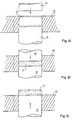
- Figures 1A to 1C illustrate the operation of a powder compression tool.
- the tool includes a die 10 with a cavity 12 arranged through it.
- This cavity 12 defines the shape or profile of the desired compact, including features such as a smooth surface, an indentation, or other characteristic.
- Die 10 co-operates with an upper punch 14 and a lower punch 15 which penetrate through both ends of the cavity 12.
- the cavity 12 is filed with metal powder flush with the upper surface of die 10.
- Lower punch 15 is at a specific position determined by the volume of powder required to obtain the desired height and density of the final product. Once cavity 12 is filled with powder, upper punch 14 is lowered.
- upper punch 14 reaches an end position determined by the pressure applied to both punches.
- a compact 17 of desired shape is then obtained in cavity 12, formed of powder particles sufficiently cohered together to allow it to be handled and carried to a sintering furnace (not shown).
- the volume of the powder decreases considerably on application of pressure.
- the volume decreases by a factor 2.3 to 2.5.
- This decrease in volume is accompanied by rubbing of the powder against the walls of the cavity 12 over the length of travel of the punch. It is thus essential to lubricate the walls of the cavity 12 to minimise friction.
- Lubrication of the walls of the cavity 12 being impractical in production, it is preferred to include the lubricant in the metal powder.
- the lubricant also comes as a powder.
- the proportion of lubricant commonly used in the metal powder is from 0.6 to 0.8% in weight.
- the lubricant is about eight times less dense that the metal powder, and occupies an incompressible volume which cannot be replaced by metal during the compression.
- the obtained compacts are porous and have a mechanical strength which is substantially lower than that of pure metal.
- final sintered density is much more significant than the so-called "theoretical maximum density" of the compact, including lubricant, before sintering. Reducing the lubricant quantity may make it possible to achieve a higher percentage of the maximum theoretical density of a particular metal powder/lubricant mixture, but even values such as 96% of maximum theoretical density correspond only to a final sintered density of 7.15 in the case of steel powder containing 0.8% lubricant.
- a final density, in the case of steel powder, of around 7.15 thus is typical of that obtained through a conventional single press/single sinter process, in which a single powder compression step is performed, at about 700 Mpa, followed by sintering to obtain the final product.
- a double press/double sinter process can be used, in which, after compression under the above-mentioned conditions, the compact undergoes a pre-sintering treatment to vaporise the lubricant, so as to empty the pores that it occupies.
- the compact is then submitted, before a final sintering, to a second compression during which the material, not yet generally integral, tends, through plastic deformation, to occupy the empty pores.
- final densities above 7.5 cannot be achieved.
- such a two-stage process is more expensive to implement than a single press/single sinter process.
- the clearance between punches and dies has always been made a small as possible. This is to avoid or at least minimise extrusion of powder through the clearance, as well as the formation of moulding flash, generally referred to as "beards".
- the clearance commonly found in typical tools ranges from 10 to 20 ⁇ m.
- Figure 2 illustrates on an enlarged scale the clearance in the tool and the deformation which take place during a compression operation.
- the nominal diameters of moving punch 14 and of cavity 12 of the die are indicated in dotted lines.
- punch 14 tends o undergo barrel deformation.
- the punch comes into contact with the die along its entire circumference while still moving. The resulting friction increases as punch 14 comes closer to its final position and the deformation also increases.
- the friction of punch 14 against die 10 may also damage the surface finish of the cavity 12, making the subsequent ejection of the compact 17 more difficult and affecting in turn its surface and that of components subsequently pressed in the die.
- the compact 17 itself also tends to undergo barrel deformation when under compression, pushing against the side walls of the cavity 12.
- the compact 17 and the walls of cavity 12 may, if excessive force has been applied, undergo permanent deformation, making the ejection of the compact more difficult.
- This ejection is normally facilitated by the presence of a sufficient amount of lubricant, of course, but to the detriment of achieving high compact density as described above.
- JP-A-6041603 proposes the production of pressed powder articles that have good surface finish and obviating cracking of a surface of punch die pair by relating the effective punch length to a maximum of 100 mm and clearance between punch and die (or a core) to a clearance of 1 to 800 ⁇ m, but without signifying achievement of high density compacts by the relationship.
- this is achieved by a single press, single sinter process in accordance with the preamble to claim 1 and characterised by the metal powder mix containing from about 0.3 to 0.5 weight % of a solid lubricant and compressing the mixture at a pressure of at least 800 Mpa.
- a further object of the present invention is to provide a compression tool which enable compacts of particularly high final density to be obtained through a single pressing process, and in accordance therewith, a metal powder compression tool according to the preamble to claim 9 is specifically adapted to form a compact according to the process of claim 1 and characterised by a second punch co-operating with the die on the side opposite to the first punch, the second punch, during a compression being arranged to seal the cavity in the vicinity of the die surface to form the compact in the cavity and flush with one surface of the die, the first punch being used to eject the compact at the end of compression and including axially protruding edges for forming recessed edge regions on the compact to accommodate beard formation.
- the increased clearance between the elements of the tool is not affected by any deformation of the elements during the compression operation.
- the presence of a significant clearance may tend to accentuate the generation of beards on the edges of the produced compacts, but such beards only affect, for the most part, the aesthetic appearance of the compacts.
- the increased clearance is preferably not greater than the mean grain size of the powder, or else the powder grains will tend to jam together in the gap, thereby increasing friction as well as causing excessive loss of powder, in an extreme case.
- the elements of the tool are arranged to form a compact having one face flush with a surface of the die.
- the tool includes a second punch (15, 14) co-operating with the cavity (12) from the side opposite to the point of entry of the first punch, the second punch, during compression, being arranged to seal the cavity at or in the vicinity of the die surface, the first punch being used to eject the compact at the end of compression.
- the first punch (15) includes axially protruding edge portions which serve to form recessed edge regions on the compact these edge regions serving to accommodate to a significant extent any beards formed.
- less than 0.5, or more preferably, less than 0.4 weight % of lubricant is included in the powder to be moulded into a compact.
- the powder includes about 0.3% weight of lubricant when the die cavity walls are coated as mentioned above.
- the green density of the compact prior to sintering is at least 7.4 g/cc
- the present invention can in the case of steel powder, achieve, by a cold, single pressing/sintering of a mixture of metal powders and significantly reduced amount of lubricant, a final density of at least 7.5.
- the nominal shapes of punch 14 and of stamp 12 are illustrated by dotted lines.
- the dimensions of the tool are chosen so that the clearance between moving punch 14 and die 10 is relatively large with respect to the clearance of a conventional tool illustrated in Figure 2. More specifically, as illustrated, this clearance is greater than the maximum radial expansion reached by punch 14 at the desired maximum compression pressure.
- this clearance is selected to be not greater than a limit at which the powder escapes from the die, This limit reaches 100 ⁇ m for commonly used metal powders, and it is greater than the mean grain size of the powder, because the grains tend to jam together in the clearance, as mentioned earlier.
- the clearance is chosen according to the diameter of the compact. For example, good results are obtained by choosing a clearance of 50 ⁇ m for diameters reaching 50mm, a clearance of 60 ⁇ m for diameters between 50 and 80mm, and a clearance of 80 ⁇ m for clearances above 80mm.
- the punch and die will undergo much less distortion as compared to the conventional tool of Figure 2 and will successfully operate at higher pressures.
- a tool according to the present invention has been successfully tested at more than 1050 MPa. Further, since the contact areas are of smaller extent and the effects of friction are lower, the wall of cavity 12 maintains an acceptable surface finish for a longer period of time in service.
- the largest practicable clearance is chosen for all the tool elements.
- these elements are generally designed to be movable one with respect to another during use so as to promote homogenisation within the compact. Further, assembly of the tool is thus facilitated by having the largest practicable clearance.
- compact 17 will exhibit greater barrel deformation than in a conventional case. As a result, compact 17 would be more difficult to eject and more lubricant would accordingly be required, which militates directly against the desired increase in density.
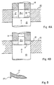
- FIGS 4A and 4B illustrate a particularly preferred form of tool according to the present invention, minimising this problem.
- the moving punch is in this case the lower punch 15 which is provided with an upwardly extending broach portion 15-1. This co-operates with a corresponding recess in the upper punch 14 to make a recess or opening in a compact 17 to be compressed.
- lower punch 15 is, as in Figure 1A, set at a specific position which determines the volume of powder contained by cavity 12. This cavity 12 is filled flush with the upper surface of die 10. Then, upper punch 14 is lowered to seal the cavity 12, if necessary by slightly penetrating into the latter. The compression operation is then performed at the top of the die by appropriately combining relative motions of the punches and of the die.
- punch 15 has reached its final position, as determined by the pressure applied to it.
- compact 17 As previously, the compression of compact 17 generates radial force which deform die 10. However, since compact 27 is then positioned towards one face of the die, the walls of cavity 12 do not deform as a barrel but, as illustrated, as an upwardly opening cone. This conical shape is partially retained when punch 14 is raised, which considerably helps the ejection of compact 17 by lower punch 15.
- the proportion of lubricant may be smaller than 0.5 weight %.
- lubricant about 0.3 weight %, may be used when the walls of the die cavity 12 are coated with a material having a low friction coefficient with the powder.
- This material should, as previously mentioned, withstand repeated forces caused by successive compression operations.
- a material which meets these requirements is DLC (Diamond Like Carbon).
- the punch edges as is shown in Figures 4A and 4B for lower punch 15, preferably slightly protrude axially because this has been found to attenuate beard formation.
- Figure 5 shows an enlarged and deliberately exaggerated view of an edge of compact 17 obtained with such an arrangement.
- the edge of compact 17 is indented with respect to the lower surface, so that beard 17-1 resulting from the clearance is entirely included within this indentation.
- beard 17-1 does not affect the technical function of the corresponding surface of the compact, if this surface is not subsequently machined.
Landscapes
- Engineering & Computer Science (AREA)
- Mechanical Engineering (AREA)
- Manufacturing & Machinery (AREA)
- Powder Metallurgy (AREA)
- Polishing Bodies And Polishing Tools (AREA)
- Superconductors And Manufacturing Methods Therefor (AREA)
- Conductive Materials (AREA)
- Preventing Corrosion Or Incrustation Of Metals (AREA)
Applications Claiming Priority (3)
| Application Number | Priority Date | Filing Date | Title |
|---|---|---|---|
| FR9709918A FR2766743B1 (fr) | 1997-07-29 | 1997-07-29 | Outillage de compression de poudre pour installation de frittage |
| FR9709918 | 1997-07-29 | ||
| PCT/EP1998/004932 WO1999006167A1 (en) | 1997-07-29 | 1998-07-23 | Metal powder compression tool |
Publications (2)
| Publication Number | Publication Date |
|---|---|
| EP0999909A1 EP0999909A1 (en) | 2000-05-17 |
| EP0999909B1 true EP0999909B1 (en) | 2003-06-25 |
Family
ID=9509964
Family Applications (1)
| Application Number | Title | Priority Date | Filing Date |
|---|---|---|---|
| EP98940252A Expired - Lifetime EP0999909B1 (en) | 1997-07-29 | 1998-07-23 | Metal powder compression tool |
Country Status (9)
| Country | Link |
|---|---|
| US (1) | US6558144B1 (es) |
| EP (1) | EP0999909B1 (es) |
| AT (1) | ATE243595T1 (es) |
| BR (1) | BR9811300A (es) |
| CA (1) | CA2298524C (es) |
| DE (1) | DE69815850T2 (es) |
| ES (1) | ES2199452T3 (es) |
| FR (1) | FR2766743B1 (es) |
| WO (1) | WO1999006167A1 (es) |
Families Citing this family (6)
| Publication number | Priority date | Publication date | Assignee | Title |
|---|---|---|---|---|
| SE0003755L (sv) * | 2000-10-17 | 2002-04-18 | Skf Ab | Metod och anordning fö pulverpressning |
| JP3644591B2 (ja) * | 2000-10-23 | 2005-04-27 | 日立粉末冶金株式会社 | 粉末成形用ダイスおよびそれを用いた粉末成形方法 |
| US6837915B2 (en) * | 2002-09-20 | 2005-01-04 | Scm Metal Products, Inc. | High density, metal-based materials having low coefficients of friction and wear rates |
| EP2307191B1 (de) * | 2008-07-02 | 2018-08-08 | Basf Se | Verfahren zur herstellung eines oxidischen geometrischen formkörpers |
| CN104742408B (zh) * | 2015-03-12 | 2016-09-07 | 中国工程物理研究院化工材料研究所 | 去除模压一次成型粉体材料飞边的模具装置 |
| JP7578508B2 (ja) * | 2021-02-25 | 2024-11-06 | シチズンファインデバイス株式会社 | 成形体の製造方法 |
Family Cites Families (8)
| Publication number | Priority date | Publication date | Assignee | Title |
|---|---|---|---|---|
| SE8003136L (sv) * | 1980-04-25 | 1981-10-26 | Asea Ab | Press for kompaktering med anvendande av ett fast lettdeformerbart tryckmedium |
| JPH0641603A (ja) * | 1992-07-24 | 1994-02-15 | Hitachi Metals Ltd | プレス成形機 |
| JPH06218587A (ja) * | 1993-01-25 | 1994-08-09 | Hitachi Tool Eng Ltd | 粉末成形用被覆金型 |
| GB9318581D0 (en) * | 1993-09-08 | 1993-10-27 | Manganese Bronze Ltd | Method of and apparatus for producing a compression product |
| SE9401623D0 (sv) * | 1994-05-09 | 1994-05-09 | Hoeganaes Ab | Sintered products having improved density |
| US5602350A (en) * | 1995-05-15 | 1997-02-11 | The Penn State Research Foundation | Method for compacting compactable materials and improved lubricant for same |
| US5594186A (en) * | 1995-07-12 | 1997-01-14 | Magnetics International, Inc. | High density metal components manufactured by powder metallurgy |
| US5754937A (en) * | 1996-05-15 | 1998-05-19 | Stackpole Limited | Hi-density forming process |
-
1997
- 1997-07-29 FR FR9709918A patent/FR2766743B1/fr not_active Expired - Fee Related
-
1998
- 1998-07-23 DE DE69815850T patent/DE69815850T2/de not_active Expired - Lifetime
- 1998-07-23 ES ES98940252T patent/ES2199452T3/es not_active Expired - Lifetime
- 1998-07-23 WO PCT/EP1998/004932 patent/WO1999006167A1/en not_active Ceased
- 1998-07-23 AT AT98940252T patent/ATE243595T1/de not_active IP Right Cessation
- 1998-07-23 EP EP98940252A patent/EP0999909B1/en not_active Expired - Lifetime
- 1998-07-23 CA CA002298524A patent/CA2298524C/en not_active Expired - Fee Related
- 1998-07-23 BR BR9811300-3A patent/BR9811300A/pt not_active IP Right Cessation
- 1998-07-23 US US09/463,682 patent/US6558144B1/en not_active Expired - Fee Related
Also Published As
| Publication number | Publication date |
|---|---|
| FR2766743A1 (fr) | 1999-02-05 |
| DE69815850D1 (de) | 2003-07-31 |
| CA2298524C (en) | 2007-04-17 |
| DE69815850T2 (de) | 2004-05-06 |
| EP0999909A1 (en) | 2000-05-17 |
| ES2199452T3 (es) | 2004-02-16 |
| US6558144B1 (en) | 2003-05-06 |
| FR2766743B1 (fr) | 1999-11-26 |
| ATE243595T1 (de) | 2003-07-15 |
| CA2298524A1 (en) | 1999-02-11 |
| WO1999006167A1 (en) | 1999-02-11 |
| BR9811300A (pt) | 2000-08-29 |
Similar Documents
| Publication | Publication Date | Title |
|---|---|---|
| EP3342586B1 (en) | Powder molding metal mold and method for manufacturing powder compacted molding | |
| US4472350A (en) | Method of making a compound valve seat | |
| US4082559A (en) | Cemented carbide products and manufacturing method | |
| US5694640A (en) | Method of and appartus for producing a compression product | |
| CN101516552A (zh) | 薄壁粉末金属部件制造 | |
| EP1201338B1 (en) | Method of sintering and forging raw material | |
| EP1027468B1 (en) | Sintered powder metal bodies and process for producing the same | |
| EP2080571B1 (en) | Method and apparatus for producing a high-strength process material | |
| CA2298524C (en) | Metal powder compression tool | |
| JPH07173504A (ja) | 圧粉成形用金型装置 | |
| US3611546A (en) | Method of highly-densifying powdered metal | |
| CN1034854C (zh) | 粉末冶金制造复合制品的方法 | |
| JP3521088B2 (ja) | 粉末冶金用の金属粉末の成形方法 | |
| RU2101137C1 (ru) | Способ изготовления двухслойных втулок | |
| JP2001131606A (ja) | 粉末成形用コアロッドおよびそれを用いた圧粉成形方法 | |
| SU1726128A1 (ru) | Способ прессовани изделий из порошка | |
| CN218134951U (zh) | 一种用于pcd复合片组装的预压成型模具 | |
| JPH0641603A (ja) | プレス成形機 | |
| JPS6137399A (ja) | 圧粉体の成形方法とその装置 | |
| JP2006299293A (ja) | 圧粉体の成形方法 | |
| JP5537865B2 (ja) | 粉末成形方法 | |
| JP2672193B2 (ja) | 液圧金型圧縮法 | |
| RU2026155C1 (ru) | Способ изготовления высокоплотных порошковых дисков | |
| SU850312A1 (ru) | Способ изготовлени спеченных изделийиз МАТЕРиАлОВ HA OCHOBE жЕлЕзА | |
| JP2003286504A (ja) | 同軸度精度に優れた内孔付き焼結部材の製造方法 |
Legal Events
| Date | Code | Title | Description |
|---|---|---|---|
| PUAI | Public reference made under article 153(3) epc to a published international application that has entered the european phase |
Free format text: ORIGINAL CODE: 0009012 |
|
| 17P | Request for examination filed |
Effective date: 20000214 |
|
| AK | Designated contracting states |
Kind code of ref document: A1 Designated state(s): AT DE ES FR GB IT |
|
| 17Q | First examination report despatched |
Effective date: 20000825 |
|
| GRAH | Despatch of communication of intention to grant a patent |
Free format text: ORIGINAL CODE: EPIDOS IGRA |
|
| GRAH | Despatch of communication of intention to grant a patent |
Free format text: ORIGINAL CODE: EPIDOS IGRA |
|
| GRAA | (expected) grant |
Free format text: ORIGINAL CODE: 0009210 |
|
| AK | Designated contracting states |
Designated state(s): AT DE ES FR GB IT |
|
| REG | Reference to a national code |
Ref country code: GB Ref legal event code: FG4D |
|
| REF | Corresponds to: |
Ref document number: 69815850 Country of ref document: DE Date of ref document: 20030731 Kind code of ref document: P |
|
| ET | Fr: translation filed | ||
| REG | Reference to a national code |
Ref country code: ES Ref legal event code: FG2A Ref document number: 2199452 Country of ref document: ES Kind code of ref document: T3 |
|
| PLBE | No opposition filed within time limit |
Free format text: ORIGINAL CODE: 0009261 |
|
| STAA | Information on the status of an ep patent application or granted ep patent |
Free format text: STATUS: NO OPPOSITION FILED WITHIN TIME LIMIT |
|
| 26N | No opposition filed |
Effective date: 20040326 |
|
| PGFP | Annual fee paid to national office [announced via postgrant information from national office to epo] |
Ref country code: ES Payment date: 20090706 Year of fee payment: 12 |
|
| PGFP | Annual fee paid to national office [announced via postgrant information from national office to epo] |
Ref country code: GB Payment date: 20090612 Year of fee payment: 12 Ref country code: AT Payment date: 20090612 Year of fee payment: 12 |
|
| PGFP | Annual fee paid to national office [announced via postgrant information from national office to epo] |
Ref country code: IT Payment date: 20090722 Year of fee payment: 12 |
|
| GBPC | Gb: european patent ceased through non-payment of renewal fee |
Effective date: 20100723 |
|
| PG25 | Lapsed in a contracting state [announced via postgrant information from national office to epo] |
Ref country code: AT Free format text: LAPSE BECAUSE OF NON-PAYMENT OF DUE FEES Effective date: 20100723 Ref country code: IT Free format text: LAPSE BECAUSE OF NON-PAYMENT OF DUE FEES Effective date: 20100723 |
|
| PG25 | Lapsed in a contracting state [announced via postgrant information from national office to epo] |
Ref country code: GB Free format text: LAPSE BECAUSE OF NON-PAYMENT OF DUE FEES Effective date: 20100723 |
|
| REG | Reference to a national code |
Ref country code: ES Ref legal event code: FD2A Effective date: 20110818 |
|
| PG25 | Lapsed in a contracting state [announced via postgrant information from national office to epo] |
Ref country code: ES Free format text: LAPSE BECAUSE OF NON-PAYMENT OF DUE FEES Effective date: 20100724 |
|
| PGFP | Annual fee paid to national office [announced via postgrant information from national office to epo] |
Ref country code: DE Payment date: 20120731 Year of fee payment: 15 Ref country code: FR Payment date: 20120712 Year of fee payment: 15 |
|
| REG | Reference to a national code |
Ref country code: FR Ref legal event code: ST Effective date: 20140331 |
|
| PG25 | Lapsed in a contracting state [announced via postgrant information from national office to epo] |
Ref country code: DE Free format text: LAPSE BECAUSE OF NON-PAYMENT OF DUE FEES Effective date: 20140201 |
|
| REG | Reference to a national code |
Ref country code: DE Ref legal event code: R119 Ref document number: 69815850 Country of ref document: DE Effective date: 20140201 |
|
| PG25 | Lapsed in a contracting state [announced via postgrant information from national office to epo] |
Ref country code: FR Free format text: LAPSE BECAUSE OF NON-PAYMENT OF DUE FEES Effective date: 20130731 |