EP0998973A1 - Cooled bundle tube reactor - Google Patents
Cooled bundle tube reactor Download PDFInfo
- Publication number
- EP0998973A1 EP0998973A1 EP98120273A EP98120273A EP0998973A1 EP 0998973 A1 EP0998973 A1 EP 0998973A1 EP 98120273 A EP98120273 A EP 98120273A EP 98120273 A EP98120273 A EP 98120273A EP 0998973 A1 EP0998973 A1 EP 0998973A1
- Authority
- EP
- European Patent Office
- Prior art keywords
- tube bundle
- sections
- tubes
- bundle reactor
- reactor according
- Prior art date
- Legal status (The legal status is an assumption and is not a legal conclusion. Google has not performed a legal analysis and makes no representation as to the accuracy of the status listed.)
- Withdrawn
Links
Images


Classifications
-
- B—PERFORMING OPERATIONS; TRANSPORTING
- B01—PHYSICAL OR CHEMICAL PROCESSES OR APPARATUS IN GENERAL
- B01J—CHEMICAL OR PHYSICAL PROCESSES, e.g. CATALYSIS OR COLLOID CHEMISTRY; THEIR RELEVANT APPARATUS
- B01J8/00—Chemical or physical processes in general, conducted in the presence of fluids and solid particles; Apparatus for such processes
- B01J8/02—Chemical or physical processes in general, conducted in the presence of fluids and solid particles; Apparatus for such processes with stationary particles, e.g. in fixed beds
- B01J8/06—Chemical or physical processes in general, conducted in the presence of fluids and solid particles; Apparatus for such processes with stationary particles, e.g. in fixed beds in tube reactors; the solid particles being arranged in tubes
- B01J8/067—Heating or cooling the reactor
-
- F—MECHANICAL ENGINEERING; LIGHTING; HEATING; WEAPONS; BLASTING
- F28—HEAT EXCHANGE IN GENERAL
- F28D—HEAT-EXCHANGE APPARATUS, NOT PROVIDED FOR IN ANOTHER SUBCLASS, IN WHICH THE HEAT-EXCHANGE MEDIA DO NOT COME INTO DIRECT CONTACT
- F28D7/00—Heat-exchange apparatus having stationary tubular conduit assemblies for both heat-exchange media, the media being in contact with different sides of a conduit wall
- F28D7/16—Heat-exchange apparatus having stationary tubular conduit assemblies for both heat-exchange media, the media being in contact with different sides of a conduit wall the conduits being arranged in parallel spaced relation
- F28D7/163—Heat-exchange apparatus having stationary tubular conduit assemblies for both heat-exchange media, the media being in contact with different sides of a conduit wall the conduits being arranged in parallel spaced relation with conduit assemblies having a particular shape, e.g. square or annular; with assemblies of conduits having different geometrical features; with multiple groups of conduits connected in series or parallel and arranged inside common casing
- F28D7/1653—Heat-exchange apparatus having stationary tubular conduit assemblies for both heat-exchange media, the media being in contact with different sides of a conduit wall the conduits being arranged in parallel spaced relation with conduit assemblies having a particular shape, e.g. square or annular; with assemblies of conduits having different geometrical features; with multiple groups of conduits connected in series or parallel and arranged inside common casing the conduit assemblies having a square or rectangular shape
-
- F—MECHANICAL ENGINEERING; LIGHTING; HEATING; WEAPONS; BLASTING
- F28—HEAT EXCHANGE IN GENERAL
- F28F—DETAILS OF HEAT-EXCHANGE AND HEAT-TRANSFER APPARATUS, OF GENERAL APPLICATION
- F28F9/00—Casings; Header boxes; Auxiliary supports for elements; Auxiliary members within casings
- F28F9/22—Arrangements for directing heat-exchange media into successive compartments, e.g. arrangements of guide plates
-
- B—PERFORMING OPERATIONS; TRANSPORTING
- B01—PHYSICAL OR CHEMICAL PROCESSES OR APPARATUS IN GENERAL
- B01J—CHEMICAL OR PHYSICAL PROCESSES, e.g. CATALYSIS OR COLLOID CHEMISTRY; THEIR RELEVANT APPARATUS
- B01J2208/00—Processes carried out in the presence of solid particles; Reactors therefor
- B01J2208/00008—Controlling the process
- B01J2208/00017—Controlling the temperature
- B01J2208/00106—Controlling the temperature by indirect heat exchange
- B01J2208/00168—Controlling the temperature by indirect heat exchange with heat exchange elements outside the bed of solid particles
- B01J2208/00212—Plates; Jackets; Cylinders
- B01J2208/00221—Plates; Jackets; Cylinders comprising baffles for guiding the flow of the heat exchange medium
-
- B—PERFORMING OPERATIONS; TRANSPORTING
- B01—PHYSICAL OR CHEMICAL PROCESSES OR APPARATUS IN GENERAL
- B01J—CHEMICAL OR PHYSICAL PROCESSES, e.g. CATALYSIS OR COLLOID CHEMISTRY; THEIR RELEVANT APPARATUS
- B01J2219/00—Chemical, physical or physico-chemical processes in general; Their relevant apparatus
- B01J2219/00761—Details of the reactor
- B01J2219/00763—Baffles
- B01J2219/00765—Baffles attached to the reactor wall
- B01J2219/00777—Baffles attached to the reactor wall horizontal
Definitions
- the invention relates to a cooled tube bundle reactor with one of a Distributor, a collector and arranged between distributor and collector Pipes with existing catalysts flow path for the reacting medium and a flow path for the cooling medium, the both media are in heat exchange via the walls of the pipes.
- Cooled tube bundle reactors are known in which the tubes of the tube bundle are summarized in the form of a cylinder, and the flow this tube bundle cylinder through the cooling medium essentially radially done from the outside in. This is to remove the heat of reaction generated cooling capacity is large, but is not evenly distributed over all reaction tubes. Some reaction tubes become stronger, others less strong cooled, which in turn influences the reaction process taking place in it.
- the invention has for its object to provide a tube bundle reactor flow rate of the individual reactor tubes as possible as possible through the cooling medium.
- the flow path for the cooling medium is composed of sections arranged parallel to one another of a rectangular channel deflected between the sections by 180 ° in each case, that the pipes pass through the sections transverse to the flow direction of the sections and the central axes of all tubes are arranged together in a rectangle or square.
- the cooling medium is guided in one particularly Rectangular channel allowing uniform flow to the reactor tubes.
- This is characterized by an almost constant width and height Velocity profile of the medium flowing through.
- reactor tubes lying in the slipstream as it were Feature a multiple deflection of the rectangular channel by 180 ° in each case, whereby mutually parallel sections of the rectangular channel result through which the reaction tubes pass transversely to the flow direction are.
- the redirection means that those pipes that were in the previous Section last due to their arrangement within the tube bundle flowed in, in the following section first with a are flowed according to increased temperature gradients. Through the Redirection is therefore an equalization of the coolant achieved individual pipes, the central axes of which are in a rectangle or Are arranged square.
- each tube up to sealing system is expanded at the edge of the respective opening.
- the widening can be done by means of an expansion probe, which is axially in the respective tube inserted, positioned there on the section of the opening of the wall and then with a very high fluid pressure is applied, causing widening of the pipe section in question up to a tight fit at the edge of the surrounding, preferably circular opening leads.
- the 180 ° deflection takes place in deflection chambers in the direction of flow are attached to the sections and across the entire width of the flow have the same cross-section.
- the cross section is rectangular.
- the cross section of the deflection chamber is essentially semicircular.
- the single ones Sections of the rectangular channel can have identical dimensions. In this way it is possible to use the tube bundle reactor according to the invention depending on the respective process parameters to be built up modularly by the adjustment on the number of sections of the Rectangular channel takes place.
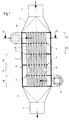
- the tube bundle reactor shown in FIG. 1 as the first embodiment consists from a distributor 1 with connecting piece 2, a collector 3 with connecting piece 4 and the tube bundle forming tubes 5 between manifolds 1 and Collector 3.
- the reaction gas reaches the distributor via the connecting piece 2 1 and from there flows through the tubes 5 filled with catalysts simultaneous chemical reaction from top to bottom.
- a suitable cooling medium flows around the tubes 5, e.g. B. a molten salt.
- the cooling medium is guided in a cross-counterflow, wherein the cooling medium is arranged over the bottom of the reactor housing Inlet port 6 enters a flow path over several Deflections 7 up to an outlet connection arranged at the top of the reactor housing 8 leads, via which the cooling medium leaves the reactor housing 9.
- the flow path of the cooling medium consists, as can be seen in FIG. 1, of individual ones Sections 10 to 14 and the 180 ° deflections 7 between them Sections 10 to 14.
- Sections 10 to 14 are therefore parallel to each other arranged, with adjacent sections 10 and 11 or 11 and 12 or 12 and 13 or 13 and 14 from each other by a common horizontal wall 15 are separated.
- Each wall 15 is provided with round openings through which the Pipes 5 are passed. All tubes 5 are in one piece, i. H. penetrate them successively all sections 10 to 14 of the flow path of the Cooling medium.
- the deflections 7 are formed in that the walls 15 do not extend over the entire width of the reactor housing 9, but only over a part, so that at the end of each section 10 to 14 an overflow cross section remains free, through which the cooling medium is deflected at the same time 180 ° into the next section.
- a total of five are arranged one above the other and identical sections 10 to 14 of the Flow channel available. This number can vary depending on the Change process parameters. Because of the identical dimensions of each one Sections 10 to 14 is in particular a modular construction of the reactor housing 9 possible, only the length of the through the reactor housing 9 passed tubes 5 must be adjusted accordingly.
- Fig. 1 shows in connection with Fig. 2 that each section 10 to 14 of the Flow channel is rectangular, both in terms of flowed cross-section as well as the shape of the tubes 5 permeated flow level.
- both Walls 15 and the side walls 16 of each section 10 to 14 are exactly parallel to each other.
- Fig. 2 shows that the tubes 5 both in the direction of flow as well as arranged transversely to it in rows, the central axes all tubes 5 together form a rectangle. Run in the direction of flow the rows in particular parallel to the two side walls 16.
- the tubes 5 must be sealed in the round openings the walls 15 sit, through which they passed at right angles are.
- tight bundling of the pipes not possible to get there with the welding electrode.
- an expansion probe is inserted axially into the tube the position in question and it becomes a large hydraulic one Generates pressure, which partially expands the pipe and thereby a friction and positive connection with the respective wall bushing.
- the circuit for the salt bath melt serving as cooling medium is not shown in FIG. 1.
- a circulation pump is provided and one behind the Outlet connector 8 arranged salt bath cooler.
- FIGS. 1 to 3 differs from that already described Embodiment through a three-stage design of the rectangular channel as well as by another constructive solution for the deflection 7.
- the in Flow direction to the sections 10, 11 attached deflection chambers 18 have a constant, essentially over the entire width of the flow semicircular cross section on and no rectangular cross section, as in the first embodiment. Due to the semicircular deflection lower pressure losses of the cooling medium arise when flowing through the reactor housing.
Landscapes
- Engineering & Computer Science (AREA)
- Physics & Mathematics (AREA)
- Thermal Sciences (AREA)
- Mechanical Engineering (AREA)
- General Engineering & Computer Science (AREA)
- Chemical & Material Sciences (AREA)
- Geometry (AREA)
- Organic Chemistry (AREA)
- Chemical Kinetics & Catalysis (AREA)
- Devices And Processes Conducted In The Presence Of Fluids And Solid Particles (AREA)
Abstract
Description
Die Erfindung betrifft einen gekühlten Rohrbündelreaktor mit einem aus einem Verteiler, einem Sammler und zwischen Verteiler und Sammler angeordneten Rohren mit darin befindlichen Katalysatoren bestehenden Strömungsweg für das reagierende Medium und einem Strömungsweg für das Kühlmedium, wobei die beiden Medien über die Wandungen der Rohre im Wärmeaustausch stehen.The invention relates to a cooled tube bundle reactor with one of a Distributor, a collector and arranged between distributor and collector Pipes with existing catalysts flow path for the reacting medium and a flow path for the cooling medium, the both media are in heat exchange via the walls of the pipes.
Bekannt sind gekühlte Rohrbündelreaktoren, bei denen die Rohre des Rohrbündels insgesamt in Gestalt eines Zylinders zusammengefaßt sind, und die Durchströmung dieses Rohrbündelzylinders durch das Kühlmedium im wesentlichen radial von außen nach innen erfolgt. Die hierbei zur Abführung der Reaktionswärme erzeugte Kühlleistung ist zwar groß, verteilt sich jedoch nicht gleichmäßig über alle Reaktionsrohre. Einige Reaktionsrohre werden stärker, andere weniger stark gekühlt, was wiederum Einfluß auf den darin stattfindenden Reaktionsprozeß hat.Cooled tube bundle reactors are known in which the tubes of the tube bundle are summarized in the form of a cylinder, and the flow this tube bundle cylinder through the cooling medium essentially radially done from the outside in. This is to remove the heat of reaction generated cooling capacity is large, but is not evenly distributed over all reaction tubes. Some reaction tubes become stronger, others less strong cooled, which in turn influences the reaction process taking place in it.
Der Erfindung liegt die Aufgabe zugrunde, einen Rohrbündelreaktor möglichst gleicher Anströmgeschwindigkeit der einzelnen Reaktorrohre durch das Kühlmedium zu schaffen.The invention has for its object to provide a tube bundle reactor flow rate of the individual reactor tubes as possible as possible through the cooling medium.
Zur Lösung dieser Aufgabe wird bei einem Rohrbündelreaktor der eingangs genannten Art vorgeschlagen, daß sich der Strömungsweg für das Kühlmedium aus parallel zueinander angeordneten Abschnitten eines zwischen den Abschnitten um jeweils 180° umgelenkten Rechteckkanals zusammensetzt, daß die Rohre quer zu der Durchströmungsrichtung der Abschnitte durch diese hindurchgeführt und die Mittelachsen aller Rohre zusammen in einem Rechteck oder Quadrat angeordnet sind. To solve this problem, it is proposed in a tube bundle reactor of the type mentioned that the flow path for the cooling medium is composed of sections arranged parallel to one another of a rectangular channel deflected between the sections by 180 ° in each case, that the pipes pass through the sections transverse to the flow direction of the sections and the central axes of all tubes are arranged together in a rectangle or square.
Die Führung des Kühlmediums erfolgt erfindungsgemäß also in einem eine besonders gleichmäßige Anströmung der Reaktorrohre ermöglichenden Rechteckkanal. Dieser zeichnet sich durch ein über seine Breite und Höhe nahezu konstantes Geschwindigkeitsprofil des durchströmenden Mediums aus. Da jedoch die in Strömungsrichtung zuerst beaufschlagten Reaktorrohre einen größeren Temperaturgradienten und damit eine bessere Kühlleistung erfahren, als die dahinter gleichsam im Windschatten liegenden Reaktorrohre, erfolgt gemäß einem weiteren Merkmal eine mehrfache Umlenkung des Rechteckkanals um jeweils 180°, wodurch sich parallel zueinander angeordnete Abschnitte des Rechteckkanals ergeben, durch die quer zu der Durchströmungsrichtung die Reaktionsrohre hindurchgeführt sind. Die Umlenkung führt dazu, daß jene Rohre, die in dem vorhergegangenen Abschnitt aufgrund ihrer Anordnung innerhalb des Rohrbündels zuletzt angeströmt wurden, in dem darauffolgenden Abschnitt als erste mit einem entsprechend erhöhten Temperaturgradienten angeströmt werden. Durch die Umlenkung wird daher eine Vergleichmäßigung der Kühlmittelbeaufschlagung der einzelnen Rohre erzielt, deren Mittelachsen zusammen in einem Rechteck oder Quadrat angeordnet sind.According to the invention, the cooling medium is guided in one particularly Rectangular channel allowing uniform flow to the reactor tubes. This is characterized by an almost constant width and height Velocity profile of the medium flowing through. However, since the in the direction of flow first reacted reactor tubes with a larger temperature gradient and thus experience better cooling performance than that behind it according to another, reactor tubes lying in the slipstream, as it were Feature a multiple deflection of the rectangular channel by 180 ° in each case, whereby mutually parallel sections of the rectangular channel result through which the reaction tubes pass transversely to the flow direction are. The redirection means that those pipes that were in the previous Section last due to their arrangement within the tube bundle flowed in, in the following section first with a are flowed according to increased temperature gradients. Through the Redirection is therefore an equalization of the coolant achieved individual pipes, the central axes of which are in a rectangle or Are arranged square.
Mit einer Ausgestaltung des Rohrbündelreaktors wird ferner vorgeschlagen, daß benachbarte Abschnitte des Rechteckkanals jeweils durch eine gemeinsame Wand getrennt sind, die mit Öffnungen versehen ist, durch die die Rohre hindurchgeführt sind. Vorzugsweise sind die Rohre abgedichtet durch die Wand hindurchgeführt, wobei diese Abdichtung dadurch erfolgt, daß jedes Rohr bis zur dichtenden Anlage am Rand der jeweiligen Öffnung aufgeweitet wird. Das Aufweiten kann mittels einer Aufweitsonde erfolgen, die axial in das jeweilige Rohr eingeführt, dort auf dem Abschnitt der Öffnung der Wand positioniert und dann mit einem sehr hohen Flüssigkeitsdruck beaufschlagt wird, was zu einer Aufweitung des betreffenden Rohrabschnittes bis zu einem dichten Anliegen am Rand der umgebenden, vorzugsweise kreisförmigen Öffnung führt. Auf diese Weise lassen sich die Rohre auch in solchen Fällen sicher in den Öffnungen der Wände befestigen, in denen angesichts der räumlichen Situation ein Verschweißen der Rohre mit den Wänden nicht möglich ist, etwa infolge für Schweißarbeiten zu eng gebündelter Rohre.With an embodiment of the tube bundle reactor, it is also proposed that adjacent sections of the rectangular channel each by a common Wall are separated, which is provided with openings through which the pipes are passed are. The pipes are preferably sealed through the wall, this sealing takes place in that each tube up to sealing system is expanded at the edge of the respective opening. The widening can be done by means of an expansion probe, which is axially in the respective tube inserted, positioned there on the section of the opening of the wall and then with a very high fluid pressure is applied, causing widening of the pipe section in question up to a tight fit at the edge of the surrounding, preferably circular opening leads. Let it this way even in such cases, the pipes are securely attached to the openings in the walls, in which, given the spatial situation, the pipes are welded together is not possible with the walls, for example as a result of welding too tightly bundled Tube.
Um eine gleichmäßige Anströmgeschwindigkeit für die einzelnen Rohre, deren Mittelachsen zusammen ein Rechteck oder Quadrat bilden, zu erzielen, ist es von Vorteil, wenn die Rohre sowohl in Durchströmungsrichtung der Abschnitte als auch quer dazu in Reihen angeordnet sind.To ensure an even flow velocity for the individual pipes, their To form central axes together to form a rectangle or square, it is from Advantage if the tubes both in the flow direction of the sections are also arranged transversely in rows.
Damit bereits beim Eintritt des Kühlmediums in den jeweiligen Abschnitt des Rechteckkanals eine über den Querschnitt möglichst gleichförmige Strömungsgeschwindigkeit vorliegt, wird gemäß einer weiteren Ausgestaltung vorgeschlagen, daß die 180°-Umlenkung in Umlenkkammern erfolgt, die in Durchströmungsrichtung an die Abschnitte angesetzt sind und die über die gesamte Breite der Durchströmung denselben Querschnitt aufweisen. Bei einer ersten Variante der Umlenkkammern ist der Querschnitt rechteckförmig. Gemäß einer zweiten Variante der Umlenkkammer ist der Querschnitt im wesentlichen halbkreisförmig. Die einzelnen Abschnitte des Rechteckkanals können identische Abmessungen aufweisen. Auf diese Weise ist es möglich, den erfindungsgemäßen Rohrbündelreaktor in Abhängigkeit von den jeweiligen Prozeßparametern modular aufzubauen, indem die Anpassung über die Anzahl der hintereinander geschalteten Abschnitte des Rechteckkanals erfolgt.So that when the cooling medium enters the respective section of the Rectangular channel has a flow velocity that is as uniform as possible over the cross section according to a further embodiment, it is proposed that the 180 ° deflection takes place in deflection chambers in the direction of flow are attached to the sections and across the entire width of the flow have the same cross-section. In a first variant of the deflection chambers the cross section is rectangular. According to a second variant The cross section of the deflection chamber is essentially semicircular. The single ones Sections of the rectangular channel can have identical dimensions. In this way it is possible to use the tube bundle reactor according to the invention depending on the respective process parameters to be built up modularly by the adjustment on the number of sections of the Rectangular channel takes place.
Weitere Einzelheiten und Vorteile des Gegenstandes der Erfindung werden nachfolgend anhand von Ausführungsbeispielen und unter Bezugnahme auf die anliegenden Zeichnungen erläutert. Auf den Zeichnungen zeigen:
- Fig. 1
- in einer Schnittdarstellung einen gekühlten Rohrbündelreaktor;
- Fig. 2
- einen Schnitt durch den Rohrbündelreaktor in der in Fig. 1 eingezeichneten horizontalen Ebene II-II;
- Fig. 3
- in einer Schnittdarstellung eine andere Ausführungsform eines erfindungsgemäßen Rohrbündelreaktors;
- Fig. 4
- einen Schnitt entlang der versetzten Schnittebene IV-IV der Fig. 3 und
- Fig. 5
- eine Ansicht von rechts des Rohrbündelreaktors nach Fig. 3.
- Fig. 1
- in a sectional view a cooled tube bundle reactor;
- Fig. 2
- a section through the tube bundle reactor in the horizontal plane II-II shown in Fig. 1;
- Fig. 3
- in a sectional view another embodiment of a tube bundle reactor according to the invention;
- Fig. 4
- a section along the offset cutting plane IV-IV of Fig. 3 and
- Fig. 5
- 3 shows a view from the right of the tube bundle reactor according to FIG. 3.
Der in Fig. 1 als erste Ausführungsform dargestellte Rohrbündelreaktor besteht
aus einem Verteiler 1 mit Anschlußstutzen 2, einem Sammler 3 mit Anschlußstutzen
4 sowie das Rohrbündel bildenden Rohren 5 zwischen Verteiler 1 und
Sammler 3. Über den Anschlußstutzen 2 gelangt das Reaktionsgas in den Verteiler
1 und durchströmt von dort die mit Katalysatoren gefüllten Rohre 5 unter
gleichzeitigem Ablauf der chemischen Reaktion von oben nach unten.The tube bundle reactor shown in FIG. 1 as the first embodiment consists
from a
Die Reaktion läuft exotherm ab, die freiwerdende Reaktionswärme muß abgeführt
werden. Hierzu werden die Rohre 5 von einem geeigneten Kühlmedium umströmt,
z. B. einer Salzschmelze. Die Führung des Kühlmediums erfolgt in einem Kreuz-Gegenstrom,
wobei das Kühlmedium über den unten an dem Reaktorgehäuse angeordneten
Einlaßstutzen 6 in einen Strömungsweg gelangt, der über mehrere
Umlenkungen 7 bis zu einem oben an dem Reaktorgehäuse angeordneten Austrittsstutzen
8 führt, über den das Kühlmedium das Reaktorgehäuse 9 verläßt.The reaction is exothermic, the heat of reaction released must be removed
become. For this purpose, a suitable cooling medium flows around the
Der Strömungsweg des Kühlmediums besteht, wie Fig. 1 erkennen läßt, aus einzelnen
Abschnitten 10 bis 14 sowie den 180°-Umlenkungen 7 zwischen diesen
Abschnitten 10 bis 14. Die Abschnitte 10 bis 14 sind daher parallel zueinander
angeordnet, wobei benachbarte Abschnitte 10 und 11 bzw. 11 und 12 bzw. 12 und
13 bzw. 13 und 14 voneinander jeweils durch eine gemeinsame horizontale Wand
15 getrennt sind. Jede Wand 15 ist mit runden Öffnungen versehen, durch die die
Rohre 5 hindurchgeführt sind. Sämtliche Rohre 5 sind einstückig, d. h. sie durchdringen
nacheinander sämtlich Abschnitte 10 bis 14 des Strömungsweges des
Kühlmediums. Die Umlenkungen 7 werden dadurch gebildet, daß sich die Wände
15 nicht über die gesamte Breite des Reaktorgehäuses 9 erstrecken, sondern nur
über einen Teil, so daß am Ende jedes Abschnittes 10 bis 14 ein Überströmquerschnitt
frei bleibt, durch den das Kühlmedium unter gleichzeitiger Umlenkung um
180° in den nächsten Abschnitt gelangt.The flow path of the cooling medium consists, as can be seen in FIG. 1, of
Bei dem Ausführungsbeispiel nach Fig. 1 sind insgesamt fünf übereinander angeordnete
und identische Abmessungen aufweisende Abschnitte 10 bis 14 des
Strömungskanals vorhanden. Diese Anzahl kann sich in Abhängigkeit von den
Verfahrensparametern ändern. Wegen der identischen Abmessungen jedes einzelnen
Abschnittes 10 bis 14 ist insbesondere ein modularer Aufbau des Reaktorgehäuses
9 möglich, wobei lediglich die Länge der durch das Reaktorgehäuse 9
hindurchgeführten Rohre 5 entsprechend angepaßt werden muß.In the exemplary embodiment according to FIG. 1, a total of five are arranged one above the other
and
Fig. 1 läßt in Verbindung mit Fig. 2 erkennen, daß jeder Abschnitt 10 bis 14 des
Strömungskanals rechteckig ausgebildet ist, und zwar sowohl hinsichtlich des
durchströmten Querschnittes als auch hinsichtlich der Gestalt der von den Rohren
5 durchdrungenen Strömungsebene. Insbesondere verlaufen daher sowohl die
Wände 15 als auch die Seitenwände 16 jedes Abschnittes 10 bis 14 exakt parallel
zueinander.Fig. 1 shows in connection with Fig. 2 that each
Infolge der Gestaltung des Strömungsweges für das Kühlmedium als mehrfach
umgelenkter Rechteckkanal werden sämtliche Rohre 5 des Rohrbündels mit nahezu
gleicher Geschwindigkeit angeströmt. Um auch bereits am Eintritt des untersten,
ersten Abschnittes 10 eine über den Strömungsquerschnitt möglichst
gleichmäßige Verteilung der Geschwindigkeit des Kühlmediums zu erzielen, führt
der Einlaßstutzen 6 über einen sich verjüngenden Verteiler 17 in diesen untersten
Abschnitt 10. Zur Erzielung einer gleichmäßigen Abströmung des Kühlmediums ist
ein dem Austrittsstutzen vorgeschalteter Sammler 17a mit einem in Strömungsrichtung
zunehmenden Querschnitt ausgebildet, um nebeneinanderliegende Rohre
5 mit derselben Geschwindigkeit anzuströmen und quer zur Strömungsrichtung
stets denselben Strömungswiderstand zu erzielen.Due to the design of the flow path for the cooling medium as multiple
deflected rectangular channel all
Desweiteren läßt Fig. 2 erkennen, daß die Rohre 5 sowohl in Durchströmungsrichtung
als auch quer dazu in Reihen angeordnet sind, wobei die Mittelachsen
aller Rohre 5 zusammen ein Rechteck ergeben. In Durchströmungsrichtung verlaufen
die Reihen insbesondere parallel zu den beiden Seitenwänden 16.Furthermore, Fig. 2 shows that the
Um Bypässe zu vermeiden, müssen die Rohre 5 abgedichtet in den runden Öffnungen
der Wände 15 sitzen, durch die sie im rechten Winkel hindurchgeführt
sind. Prinzipiell ist es möglich, die Rohre im Bereich der Wanddurchgänge jeweils
zu verschweißen. Jedoch ist es wegen der Vielzahl und vor allem engen Bündelung
der Rohre nicht möglich, dort mit der Schweißelektrode hinzugelangen. Zur
Abdichtung der Rohre in den Öffnungen der Wände 15 wird daher ein Verfahren
angewandt, bei dem jedes Rohr bis zur dichten Anlagen am Rand der Öffnung
aufgeweitet wird. Hierzu wird eine Aufweitsonde axial in das Rohr eingeführt, an
der betreffenden Stelle positioniert und es wird dann ein großer hydraulischer
Druck erzeugt, wodurch sich das Rohr partiell aufweitet und dabei eine reib- und
formschlüssige Verbindung mit der jeweiligen Wanddurchführung eingeht. To avoid bypasses, the
Nicht dargestellt in Fig. 1 ist der Kreislauf für die als Kühlmedium dienende Salzbadschmelze.
Hierzu ist eine Umlaufpumpe vorgesehen sowie ein hinter dem
Austrittsstutzen 8 angeordneter Salzbadkühler.The circuit for the salt bath melt serving as cooling medium is not shown in FIG. 1.
For this purpose, a circulation pump is provided and one behind the
Die Ausführungsform nach den Fig. 1 bis 3 unterscheidet sich von der bereits beschriebenen
Ausführungsform durch eine dreistufige Ausbildung des Rechteckkanals
sowie durch eine andere konstruktive Lösung für die Umlenkung 7. Die in
Durchströmungsrichtung an die Abschnitte 10, 11 angesetzten Umlenkkammern
18 weisen über die gesamte Breite der Durchströmung einen konstanten, im wesentlichen
halbkreisförmigen Querschnitt auf und keinen rechteckigen Querschnitt,
wie bei dem ersten Ausführungsbeispiel. Durch die halbkreisförmige Umlenkung
entstehen geringere Druckverluste des Kühlmediums beim Durchströmen des Reaktorgehäuses. The embodiment according to FIGS. 1 to 3 differs from that already described
Embodiment through a three-stage design of the rectangular channel
as well as by another constructive solution for the
- 11
- VerteilerDistributor
- 22nd
- AnschlußstutzenConnecting piece
- 33rd
- SammlerCollector
- 44th
- AnschlußstutzenConnecting piece
- 55
- Rohrpipe
- 66
- EinlaßstutzenInlet connector
- 77
- UmlenkungRedirection
- 88th
- AustrittsstutzenOutlet connection
- 99
- ReaktorgehäuseReactor housing
- 1010th
- Abschnitt des KanalsSection of the canal
- 1111
- Abschnitt des KanalsSection of the canal
- 1212th
- Abschnitt des KanalsSection of the canal
- 1313
- Abschnitt des KanalsSection of the canal
- 1414
- Abschnitt des KanalsSection of the canal
- 1515
- Wandwall
- 1616
- SeitenwandSide wall
- 1717th
- VerteilerDistributor
- 17a17a
- SammlerCollector
- 1818th
- UmlenkkammerDeflection chamber
Claims (9)
dadurch gekennzeichnet,
daß sich der Strömungsweg für das Kühlmedium aus parallel zueinander angeordneten Abschnitten (10 bis 14) eines zwischen den Abschnitten um jeweils 180° umgelenkten Rechteckkanals zusammensetzt, daß die Rohre (5) quer zu der Durchströmungsrichtung der Abschnitte (10 bis 14) durch diese hindurchgeführt und daß die Mittelachsen aller Rohre (5) zusammen in einem Rechteck oder Quadrat angeordnet sind.Cooled tube bundle reactor with a flow path for the reacting medium and a flow path for the cooling medium, consisting of a distributor (1), a collector (3) and between the distributor (1) and collector (3) arranged tubes (5) with catalysts therein, wherein the two media are in heat exchange via the walls of the tubes (5),
characterized,
that the flow path for the cooling medium is composed of mutually parallel sections (10 to 14) of a rectangular channel deflected between the sections by 180 ° in each case, that the tubes (5) are guided through them transversely to the flow direction of the sections (10 to 14) and that the central axes of all tubes (5) are arranged together in a rectangle or square.
Priority Applications (1)
| Application Number | Priority Date | Filing Date | Title |
|---|---|---|---|
| EP98120273A EP0998973A1 (en) | 1998-10-27 | 1998-10-27 | Cooled bundle tube reactor |
Applications Claiming Priority (1)
| Application Number | Priority Date | Filing Date | Title |
|---|---|---|---|
| EP98120273A EP0998973A1 (en) | 1998-10-27 | 1998-10-27 | Cooled bundle tube reactor |
Publications (1)
| Publication Number | Publication Date |
|---|---|
| EP0998973A1 true EP0998973A1 (en) | 2000-05-10 |
Family
ID=8232864
Family Applications (1)
| Application Number | Title | Priority Date | Filing Date |
|---|---|---|---|
| EP98120273A Withdrawn EP0998973A1 (en) | 1998-10-27 | 1998-10-27 | Cooled bundle tube reactor |
Country Status (1)
| Country | Link |
|---|---|
| EP (1) | EP0998973A1 (en) |
Cited By (9)
| Publication number | Priority date | Publication date | Assignee | Title |
|---|---|---|---|---|
| WO2002072252A1 (en) * | 2001-03-12 | 2002-09-19 | Forschungszentrum Jülich GmbH | Reactor having a uniform distribution of operating materials |
| WO2003072237A1 (en) * | 2002-02-27 | 2003-09-04 | Basf Aktiengesellschaft | Reactor and method for producing phosgene |
| CN102012180A (en) * | 2010-11-12 | 2011-04-13 | 山东北辰压力容器有限公司 | Rectangular all-welded tubular heat supply network heater |
| WO2014086551A1 (en) * | 2012-12-07 | 2014-06-12 | Bayerische Motoren Werke Aktiengesellschaft | Reactor for liberating hydrogen |
| CN105817186A (en) * | 2016-04-21 | 2016-08-03 | 广东椰氏实业股份有限公司 | Integral oil bath type pipeline reactor and realization method thereof |
| CN106091485A (en) * | 2016-06-21 | 2016-11-09 | 南京冷德节能科技有限公司 | Single process side's housing dry evaporator |
| WO2020233921A1 (en) * | 2019-05-20 | 2020-11-26 | Basf Se | Process and reactor for producing phosgene |
| CN113950604A (en) * | 2019-05-28 | 2022-01-18 | 苏尔寿管理有限公司 | Tube bundle heat exchanger comprising an assembly/built-in element formed by a deflection surface and a guide section |
| CN116878314A (en) * | 2023-07-21 | 2023-10-13 | 青岛钛钽铌锆连续化反应器有限公司 | Compact array short-distance radial heat exchange slit reaction multifunctional module |
Citations (4)
| Publication number | Priority date | Publication date | Assignee | Title |
|---|---|---|---|---|
| US1900857A (en) * | 1929-07-15 | 1933-03-07 | Calco Chemical Company | Apparatus for use in the catalytic oxidation of gases |
| US3807963A (en) * | 1972-03-09 | 1974-04-30 | J Smith | Reaction apparatus |
| GB1535719A (en) * | 1975-12-09 | 1978-12-13 | Prestcold Ltd | Heat exchanger |
| WO1997025136A1 (en) * | 1996-01-09 | 1997-07-17 | Imperial Chemical Industries Plc | Heat exchange catalytic reactor |
-
1998
- 1998-10-27 EP EP98120273A patent/EP0998973A1/en not_active Withdrawn
Patent Citations (4)
| Publication number | Priority date | Publication date | Assignee | Title |
|---|---|---|---|---|
| US1900857A (en) * | 1929-07-15 | 1933-03-07 | Calco Chemical Company | Apparatus for use in the catalytic oxidation of gases |
| US3807963A (en) * | 1972-03-09 | 1974-04-30 | J Smith | Reaction apparatus |
| GB1535719A (en) * | 1975-12-09 | 1978-12-13 | Prestcold Ltd | Heat exchanger |
| WO1997025136A1 (en) * | 1996-01-09 | 1997-07-17 | Imperial Chemical Industries Plc | Heat exchange catalytic reactor |
Cited By (13)
| Publication number | Priority date | Publication date | Assignee | Title |
|---|---|---|---|---|
| WO2002072252A1 (en) * | 2001-03-12 | 2002-09-19 | Forschungszentrum Jülich GmbH | Reactor having a uniform distribution of operating materials |
| US8821829B2 (en) | 2002-02-27 | 2014-09-02 | Basf Aktiengesellschaft | Reactor and process for preparing phosgene |
| WO2003072237A1 (en) * | 2002-02-27 | 2003-09-04 | Basf Aktiengesellschaft | Reactor and method for producing phosgene |
| CN1302842C (en) * | 2002-02-27 | 2007-03-07 | 巴斯福股份公司 | Reactor and method for producing phosgene |
| US8409539B2 (en) | 2002-02-27 | 2013-04-02 | Basf Aktiengesellschaft | Reactor and method for producing phosgene |
| CN102012180A (en) * | 2010-11-12 | 2011-04-13 | 山东北辰压力容器有限公司 | Rectangular all-welded tubular heat supply network heater |
| CN102012180B (en) * | 2010-11-12 | 2012-09-05 | 山东北辰机电设备股份有限公司 | Rectangular all-welded tubular heat supply network heater |
| WO2014086551A1 (en) * | 2012-12-07 | 2014-06-12 | Bayerische Motoren Werke Aktiengesellschaft | Reactor for liberating hydrogen |
| CN105817186A (en) * | 2016-04-21 | 2016-08-03 | 广东椰氏实业股份有限公司 | Integral oil bath type pipeline reactor and realization method thereof |
| CN106091485A (en) * | 2016-06-21 | 2016-11-09 | 南京冷德节能科技有限公司 | Single process side's housing dry evaporator |
| WO2020233921A1 (en) * | 2019-05-20 | 2020-11-26 | Basf Se | Process and reactor for producing phosgene |
| CN113950604A (en) * | 2019-05-28 | 2022-01-18 | 苏尔寿管理有限公司 | Tube bundle heat exchanger comprising an assembly/built-in element formed by a deflection surface and a guide section |
| CN116878314A (en) * | 2023-07-21 | 2023-10-13 | 青岛钛钽铌锆连续化反应器有限公司 | Compact array short-distance radial heat exchange slit reaction multifunctional module |
Similar Documents
| Publication | Publication Date | Title |
|---|---|---|
| EP1042641B1 (en) | Heat exchanger tubular block and a multi-chamber flat tube which can be used therefor | |
| DE2907810C2 (en) | Heat exchangers for conducting gases with widely differing temperatures | |
| EP2304370B1 (en) | Conversion set for a tube bundle heat exchanger | |
| EP3585509B1 (en) | Heat exchanger and reactor | |
| DE10260030A1 (en) | Heat exchanger, especially for vehicle, has housing and cover plate for through channel(s) with coaxial openings via which collection chamber(s) communicates with through channel(s) | |
| DE60113386T2 (en) | MEMBRANE MODULE FOR SEPARATING FLUID MIXTURES | |
| DE69003404T3 (en) | Multi-tube type heat exchanger. | |
| EP0387678A1 (en) | Heat exchanger and process for the watertight fixation of heat exchange elements to an end plate | |
| DE4432972A1 (en) | Heat exchanger having two rows of tubes (pipes), in particular for motor vehicles | |
| EP0228581A1 (en) | Heat-exchanger | |
| EP1936311B1 (en) | Compact plate heat exchanger | |
| DE2842746A1 (en) | HEAT EXCHANGE DEVICE | |
| EP0998973A1 (en) | Cooled bundle tube reactor | |
| DE19540907C5 (en) | Spinning beam for spinning a plurality of synthetic threads and its manufacture | |
| DE2033128B2 (en) | Heat exchange unit with heat exchangers in which rows of tubes are enclosed by an intermediate jacket within an outer jacket | |
| EP2136175B1 (en) | Heat transfer plate, plate pair, plate stack, compact plate heat exchanger and its manufacturing process | |
| DE2903543C2 (en) | Liquid heat exchangers, in particular oil coolers for vehicles through which water flows | |
| EP0180086A2 (en) | Oil cooler | |
| DE3138665C2 (en) | ||
| WO2001039857A1 (en) | Filter membrane module comprising an integrated heat exchanger | |
| WO2016131787A1 (en) | Shell and tube heat exchanger having sequentially arranged shell and tube components | |
| WO1992000129A1 (en) | Column body to take plate-type heat exchangers | |
| DE19529227C2 (en) | Storage block for regenerative heat exchangers | |
| DE2804113A1 (en) | BRACKET FOR FASTENING THE TUBES OF A HEAT EXCHANGER | |
| DE3538515C2 (en) |
Legal Events
| Date | Code | Title | Description |
|---|---|---|---|
| PUAI | Public reference made under article 153(3) epc to a published international application that has entered the european phase |
Free format text: ORIGINAL CODE: 0009012 |
|
| AK | Designated contracting states |
Kind code of ref document: A1 Designated state(s): AT BE CH CY DE DK ES FI FR GB GR IE IT LI LU MC NL PT SE |
|
| AX | Request for extension of the european patent |
Free format text: AL;LT;LV;MK;RO;SI |
|
| 17P | Request for examination filed |
Effective date: 20001013 |
|
| AKX | Designation fees paid |
Free format text: AT BE DE DK ES FR GB IT NL PT SE |
|
| AXX | Extension fees paid |
Free format text: RO PAYMENT 20001013 |
|
| STAA | Information on the status of an ep patent application or granted ep patent |
Free format text: STATUS: THE APPLICATION HAS BEEN WITHDRAWN |
|
| 18W | Application withdrawn |
Withdrawal date: 20021115 |