EP0998973A1 - Réacteur à faisceau de tubes refroidis - Google Patents
Réacteur à faisceau de tubes refroidis Download PDFInfo
- Publication number
- EP0998973A1 EP0998973A1 EP98120273A EP98120273A EP0998973A1 EP 0998973 A1 EP0998973 A1 EP 0998973A1 EP 98120273 A EP98120273 A EP 98120273A EP 98120273 A EP98120273 A EP 98120273A EP 0998973 A1 EP0998973 A1 EP 0998973A1
- Authority
- EP
- European Patent Office
- Prior art keywords
- tube bundle
- sections
- tubes
- bundle reactor
- reactor according
- Prior art date
- Legal status (The legal status is an assumption and is not a legal conclusion. Google has not performed a legal analysis and makes no representation as to the accuracy of the status listed.)
- Withdrawn
Links
Images


Classifications
-
- B—PERFORMING OPERATIONS; TRANSPORTING
- B01—PHYSICAL OR CHEMICAL PROCESSES OR APPARATUS IN GENERAL
- B01J—CHEMICAL OR PHYSICAL PROCESSES, e.g. CATALYSIS OR COLLOID CHEMISTRY; THEIR RELEVANT APPARATUS
- B01J8/00—Chemical or physical processes in general, conducted in the presence of fluids and solid particles; Apparatus for such processes
- B01J8/02—Chemical or physical processes in general, conducted in the presence of fluids and solid particles; Apparatus for such processes with stationary particles, e.g. in fixed beds
- B01J8/06—Chemical or physical processes in general, conducted in the presence of fluids and solid particles; Apparatus for such processes with stationary particles, e.g. in fixed beds in tube reactors; the solid particles being arranged in tubes
- B01J8/067—Heating or cooling the reactor
-
- F—MECHANICAL ENGINEERING; LIGHTING; HEATING; WEAPONS; BLASTING
- F28—HEAT EXCHANGE IN GENERAL
- F28D—HEAT-EXCHANGE APPARATUS, NOT PROVIDED FOR IN ANOTHER SUBCLASS, IN WHICH THE HEAT-EXCHANGE MEDIA DO NOT COME INTO DIRECT CONTACT
- F28D7/00—Heat-exchange apparatus having stationary tubular conduit assemblies for both heat-exchange media, the media being in contact with different sides of a conduit wall
- F28D7/16—Heat-exchange apparatus having stationary tubular conduit assemblies for both heat-exchange media, the media being in contact with different sides of a conduit wall the conduits being arranged in parallel spaced relation
- F28D7/163—Heat-exchange apparatus having stationary tubular conduit assemblies for both heat-exchange media, the media being in contact with different sides of a conduit wall the conduits being arranged in parallel spaced relation with conduit assemblies having a particular shape, e.g. square or annular; with assemblies of conduits having different geometrical features; with multiple groups of conduits connected in series or parallel and arranged inside common casing
- F28D7/1653—Heat-exchange apparatus having stationary tubular conduit assemblies for both heat-exchange media, the media being in contact with different sides of a conduit wall the conduits being arranged in parallel spaced relation with conduit assemblies having a particular shape, e.g. square or annular; with assemblies of conduits having different geometrical features; with multiple groups of conduits connected in series or parallel and arranged inside common casing the conduit assemblies having a square or rectangular shape
-
- F—MECHANICAL ENGINEERING; LIGHTING; HEATING; WEAPONS; BLASTING
- F28—HEAT EXCHANGE IN GENERAL
- F28F—DETAILS OF HEAT-EXCHANGE AND HEAT-TRANSFER APPARATUS, OF GENERAL APPLICATION
- F28F9/00—Casings; Header boxes; Auxiliary supports for elements; Auxiliary members within casings
- F28F9/22—Arrangements for directing heat-exchange media into successive compartments, e.g. arrangements of guide plates
-
- B—PERFORMING OPERATIONS; TRANSPORTING
- B01—PHYSICAL OR CHEMICAL PROCESSES OR APPARATUS IN GENERAL
- B01J—CHEMICAL OR PHYSICAL PROCESSES, e.g. CATALYSIS OR COLLOID CHEMISTRY; THEIR RELEVANT APPARATUS
- B01J2208/00—Processes carried out in the presence of solid particles; Reactors therefor
- B01J2208/00008—Controlling the process
- B01J2208/00017—Controlling the temperature
- B01J2208/00106—Controlling the temperature by indirect heat exchange
- B01J2208/00168—Controlling the temperature by indirect heat exchange with heat exchange elements outside the bed of solid particles
- B01J2208/00212—Plates; Jackets; Cylinders
- B01J2208/00221—Plates; Jackets; Cylinders comprising baffles for guiding the flow of the heat exchange medium
-
- B—PERFORMING OPERATIONS; TRANSPORTING
- B01—PHYSICAL OR CHEMICAL PROCESSES OR APPARATUS IN GENERAL
- B01J—CHEMICAL OR PHYSICAL PROCESSES, e.g. CATALYSIS OR COLLOID CHEMISTRY; THEIR RELEVANT APPARATUS
- B01J2219/00—Chemical, physical or physico-chemical processes in general; Their relevant apparatus
- B01J2219/00761—Details of the reactor
- B01J2219/00763—Baffles
- B01J2219/00765—Baffles attached to the reactor wall
- B01J2219/00777—Baffles attached to the reactor wall horizontal
Definitions
- the invention relates to a cooled tube bundle reactor with one of a Distributor, a collector and arranged between distributor and collector Pipes with existing catalysts flow path for the reacting medium and a flow path for the cooling medium, the both media are in heat exchange via the walls of the pipes.
- Cooled tube bundle reactors are known in which the tubes of the tube bundle are summarized in the form of a cylinder, and the flow this tube bundle cylinder through the cooling medium essentially radially done from the outside in. This is to remove the heat of reaction generated cooling capacity is large, but is not evenly distributed over all reaction tubes. Some reaction tubes become stronger, others less strong cooled, which in turn influences the reaction process taking place in it.
- the invention has for its object to provide a tube bundle reactor flow rate of the individual reactor tubes as possible as possible through the cooling medium.
- the flow path for the cooling medium is composed of sections arranged parallel to one another of a rectangular channel deflected between the sections by 180 ° in each case, that the pipes pass through the sections transverse to the flow direction of the sections and the central axes of all tubes are arranged together in a rectangle or square.
- the cooling medium is guided in one particularly Rectangular channel allowing uniform flow to the reactor tubes.
- This is characterized by an almost constant width and height Velocity profile of the medium flowing through.
- reactor tubes lying in the slipstream as it were Feature a multiple deflection of the rectangular channel by 180 ° in each case, whereby mutually parallel sections of the rectangular channel result through which the reaction tubes pass transversely to the flow direction are.
- the redirection means that those pipes that were in the previous Section last due to their arrangement within the tube bundle flowed in, in the following section first with a are flowed according to increased temperature gradients. Through the Redirection is therefore an equalization of the coolant achieved individual pipes, the central axes of which are in a rectangle or Are arranged square.
- each tube up to sealing system is expanded at the edge of the respective opening.
- the widening can be done by means of an expansion probe, which is axially in the respective tube inserted, positioned there on the section of the opening of the wall and then with a very high fluid pressure is applied, causing widening of the pipe section in question up to a tight fit at the edge of the surrounding, preferably circular opening leads.
- the 180 ° deflection takes place in deflection chambers in the direction of flow are attached to the sections and across the entire width of the flow have the same cross-section.
- the cross section is rectangular.
- the cross section of the deflection chamber is essentially semicircular.
- the single ones Sections of the rectangular channel can have identical dimensions. In this way it is possible to use the tube bundle reactor according to the invention depending on the respective process parameters to be built up modularly by the adjustment on the number of sections of the Rectangular channel takes place.
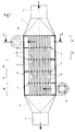
- the tube bundle reactor shown in FIG. 1 as the first embodiment consists from a distributor 1 with connecting piece 2, a collector 3 with connecting piece 4 and the tube bundle forming tubes 5 between manifolds 1 and Collector 3.
- the reaction gas reaches the distributor via the connecting piece 2 1 and from there flows through the tubes 5 filled with catalysts simultaneous chemical reaction from top to bottom.
- a suitable cooling medium flows around the tubes 5, e.g. B. a molten salt.
- the cooling medium is guided in a cross-counterflow, wherein the cooling medium is arranged over the bottom of the reactor housing Inlet port 6 enters a flow path over several Deflections 7 up to an outlet connection arranged at the top of the reactor housing 8 leads, via which the cooling medium leaves the reactor housing 9.
- the flow path of the cooling medium consists, as can be seen in FIG. 1, of individual ones Sections 10 to 14 and the 180 ° deflections 7 between them Sections 10 to 14.
- Sections 10 to 14 are therefore parallel to each other arranged, with adjacent sections 10 and 11 or 11 and 12 or 12 and 13 or 13 and 14 from each other by a common horizontal wall 15 are separated.
- Each wall 15 is provided with round openings through which the Pipes 5 are passed. All tubes 5 are in one piece, i. H. penetrate them successively all sections 10 to 14 of the flow path of the Cooling medium.
- the deflections 7 are formed in that the walls 15 do not extend over the entire width of the reactor housing 9, but only over a part, so that at the end of each section 10 to 14 an overflow cross section remains free, through which the cooling medium is deflected at the same time 180 ° into the next section.
- a total of five are arranged one above the other and identical sections 10 to 14 of the Flow channel available. This number can vary depending on the Change process parameters. Because of the identical dimensions of each one Sections 10 to 14 is in particular a modular construction of the reactor housing 9 possible, only the length of the through the reactor housing 9 passed tubes 5 must be adjusted accordingly.
- Fig. 1 shows in connection with Fig. 2 that each section 10 to 14 of the Flow channel is rectangular, both in terms of flowed cross-section as well as the shape of the tubes 5 permeated flow level.
- both Walls 15 and the side walls 16 of each section 10 to 14 are exactly parallel to each other.
- Fig. 2 shows that the tubes 5 both in the direction of flow as well as arranged transversely to it in rows, the central axes all tubes 5 together form a rectangle. Run in the direction of flow the rows in particular parallel to the two side walls 16.
- the tubes 5 must be sealed in the round openings the walls 15 sit, through which they passed at right angles are.
- tight bundling of the pipes not possible to get there with the welding electrode.
- an expansion probe is inserted axially into the tube the position in question and it becomes a large hydraulic one Generates pressure, which partially expands the pipe and thereby a friction and positive connection with the respective wall bushing.
- the circuit for the salt bath melt serving as cooling medium is not shown in FIG. 1.
- a circulation pump is provided and one behind the Outlet connector 8 arranged salt bath cooler.
- FIGS. 1 to 3 differs from that already described Embodiment through a three-stage design of the rectangular channel as well as by another constructive solution for the deflection 7.
- the in Flow direction to the sections 10, 11 attached deflection chambers 18 have a constant, essentially over the entire width of the flow semicircular cross section on and no rectangular cross section, as in the first embodiment. Due to the semicircular deflection lower pressure losses of the cooling medium arise when flowing through the reactor housing.
Landscapes
- Engineering & Computer Science (AREA)
- Physics & Mathematics (AREA)
- Thermal Sciences (AREA)
- Mechanical Engineering (AREA)
- General Engineering & Computer Science (AREA)
- Chemical & Material Sciences (AREA)
- Geometry (AREA)
- Organic Chemistry (AREA)
- Chemical Kinetics & Catalysis (AREA)
- Devices And Processes Conducted In The Presence Of Fluids And Solid Particles (AREA)
Priority Applications (1)
| Application Number | Priority Date | Filing Date | Title |
|---|---|---|---|
| EP98120273A EP0998973A1 (fr) | 1998-10-27 | 1998-10-27 | Réacteur à faisceau de tubes refroidis |
Applications Claiming Priority (1)
| Application Number | Priority Date | Filing Date | Title |
|---|---|---|---|
| EP98120273A EP0998973A1 (fr) | 1998-10-27 | 1998-10-27 | Réacteur à faisceau de tubes refroidis |
Publications (1)
| Publication Number | Publication Date |
|---|---|
| EP0998973A1 true EP0998973A1 (fr) | 2000-05-10 |
Family
ID=8232864
Family Applications (1)
| Application Number | Title | Priority Date | Filing Date |
|---|---|---|---|
| EP98120273A Withdrawn EP0998973A1 (fr) | 1998-10-27 | 1998-10-27 | Réacteur à faisceau de tubes refroidis |
Country Status (1)
| Country | Link |
|---|---|
| EP (1) | EP0998973A1 (fr) |
Cited By (9)
| Publication number | Priority date | Publication date | Assignee | Title |
|---|---|---|---|---|
| WO2002072252A1 (fr) * | 2001-03-12 | 2002-09-19 | Forschungszentrum Jülich GmbH | Reacteur a repartition uniforme des moyens de fonctionnement |
| WO2003072237A1 (fr) * | 2002-02-27 | 2003-09-04 | Basf Aktiengesellschaft | Reacteur et procede de production de phosgene |
| CN102012180A (zh) * | 2010-11-12 | 2011-04-13 | 山东北辰压力容器有限公司 | 矩形全焊接管壳式热网加热器 |
| WO2014086551A1 (fr) * | 2012-12-07 | 2014-06-12 | Bayerische Motoren Werke Aktiengesellschaft | Réacteur pour le dégagement d'hydrogène |
| CN105817186A (zh) * | 2016-04-21 | 2016-08-03 | 广东椰氏实业股份有限公司 | 一种整体油浴式管道反应器及其实现方法 |
| CN106091485A (zh) * | 2016-06-21 | 2016-11-09 | 南京冷德节能科技有限公司 | 单流程方壳体干式蒸发器 |
| WO2020233921A1 (fr) * | 2019-05-20 | 2020-11-26 | Basf Se | Procédé et réacteur de fabrication de phosgène |
| CN113950604A (zh) * | 2019-05-28 | 2022-01-18 | 苏尔寿管理有限公司 | 包括由偏转表面和引导区段形成的组件/内置元件的管束式热交换器 |
| CN116878314A (zh) * | 2023-07-21 | 2023-10-13 | 青岛钛钽铌锆连续化反应器有限公司 | 一种密集阵短距径向换热狭缝反应多功能模块 |
Citations (4)
| Publication number | Priority date | Publication date | Assignee | Title |
|---|---|---|---|---|
| US1900857A (en) * | 1929-07-15 | 1933-03-07 | Calco Chemical Company | Apparatus for use in the catalytic oxidation of gases |
| US3807963A (en) * | 1972-03-09 | 1974-04-30 | J Smith | Reaction apparatus |
| GB1535719A (en) * | 1975-12-09 | 1978-12-13 | Prestcold Ltd | Heat exchanger |
| WO1997025136A1 (fr) * | 1996-01-09 | 1997-07-17 | Imperial Chemical Industries Plc | Reacteur catalytique a echangeur thermique |
-
1998
- 1998-10-27 EP EP98120273A patent/EP0998973A1/fr not_active Withdrawn
Patent Citations (4)
| Publication number | Priority date | Publication date | Assignee | Title |
|---|---|---|---|---|
| US1900857A (en) * | 1929-07-15 | 1933-03-07 | Calco Chemical Company | Apparatus for use in the catalytic oxidation of gases |
| US3807963A (en) * | 1972-03-09 | 1974-04-30 | J Smith | Reaction apparatus |
| GB1535719A (en) * | 1975-12-09 | 1978-12-13 | Prestcold Ltd | Heat exchanger |
| WO1997025136A1 (fr) * | 1996-01-09 | 1997-07-17 | Imperial Chemical Industries Plc | Reacteur catalytique a echangeur thermique |
Cited By (13)
| Publication number | Priority date | Publication date | Assignee | Title |
|---|---|---|---|---|
| WO2002072252A1 (fr) * | 2001-03-12 | 2002-09-19 | Forschungszentrum Jülich GmbH | Reacteur a repartition uniforme des moyens de fonctionnement |
| US8821829B2 (en) | 2002-02-27 | 2014-09-02 | Basf Aktiengesellschaft | Reactor and process for preparing phosgene |
| WO2003072237A1 (fr) * | 2002-02-27 | 2003-09-04 | Basf Aktiengesellschaft | Reacteur et procede de production de phosgene |
| CN1302842C (zh) * | 2002-02-27 | 2007-03-07 | 巴斯福股份公司 | 用于生产光气的反应器和方法 |
| US8409539B2 (en) | 2002-02-27 | 2013-04-02 | Basf Aktiengesellschaft | Reactor and method for producing phosgene |
| CN102012180A (zh) * | 2010-11-12 | 2011-04-13 | 山东北辰压力容器有限公司 | 矩形全焊接管壳式热网加热器 |
| CN102012180B (zh) * | 2010-11-12 | 2012-09-05 | 山东北辰机电设备股份有限公司 | 矩形全焊接管壳式热网加热器 |
| WO2014086551A1 (fr) * | 2012-12-07 | 2014-06-12 | Bayerische Motoren Werke Aktiengesellschaft | Réacteur pour le dégagement d'hydrogène |
| CN105817186A (zh) * | 2016-04-21 | 2016-08-03 | 广东椰氏实业股份有限公司 | 一种整体油浴式管道反应器及其实现方法 |
| CN106091485A (zh) * | 2016-06-21 | 2016-11-09 | 南京冷德节能科技有限公司 | 单流程方壳体干式蒸发器 |
| WO2020233921A1 (fr) * | 2019-05-20 | 2020-11-26 | Basf Se | Procédé et réacteur de fabrication de phosgène |
| CN113950604A (zh) * | 2019-05-28 | 2022-01-18 | 苏尔寿管理有限公司 | 包括由偏转表面和引导区段形成的组件/内置元件的管束式热交换器 |
| CN116878314A (zh) * | 2023-07-21 | 2023-10-13 | 青岛钛钽铌锆连续化反应器有限公司 | 一种密集阵短距径向换热狭缝反应多功能模块 |
Similar Documents
| Publication | Publication Date | Title |
|---|---|---|
| EP1042641B1 (fr) | Bloc tubulaire d'echangeur thermique et tube plat multichambre utilisable a cet effet | |
| DE2907810C2 (de) | Wärmetauscher zur Führung von Gasen stark unterschiedlicher Temperaturen | |
| EP2304370B1 (fr) | Jeu d adaptation pour un échangeur de chaleur à faisceau tubulaire | |
| EP3585509B1 (fr) | Échangeur de chaleur et réacteur | |
| DE10260030A1 (de) | Wärmeübertrager, insbesondere für ein Kraftfahrzeug | |
| DE60113386T2 (de) | Membranmodul zur trennung von fluiden mischungen | |
| DE69003404T3 (de) | Mehrrohrtypwärmetauscher. | |
| EP0387678A1 (fr) | Echangeur de chaleur et procédé pour la fixation étanche des éléments d'échange dans une plaque d'extrémité | |
| DE4432972A1 (de) | Wärmetauscher mit zwei Rohrreihen, insbesondere für Kraftfahrzeuge | |
| EP0228581A1 (fr) | Echangeur | |
| EP1936311B1 (fr) | Échangeur de chaleur compact à plaques | |
| DE2842746A1 (de) | Waermeaustauschvorrichtung | |
| EP0998973A1 (fr) | Réacteur à faisceau de tubes refroidis | |
| DE19540907C5 (de) | Spinnbalken zum Spinnen einer Mehrzahl von synthetischen Fäden und dessen Herstellung | |
| EP2136175B1 (fr) | Plaque d'échange de chaleur, paire de plaques, pile de plaques, échangeur de chaleur à plaques compactes et son procédé de fabriquation | |
| DE2903543C2 (de) | Flüssigkeitswärmetauscher, insbesondere wasserdurchströmter Ölkühler für Fahrzeuge | |
| DE3020557C2 (de) | Kreuzstrom-Plattenwärmetauscher als Ölkühler für Brennkraftmaschinen, insbesondere von Kraftfahrzeugen | |
| DE3138665C2 (fr) | ||
| WO2001039857A1 (fr) | Module membranaire de filtration avec echangeur de chaleur integre | |
| WO1992000129A1 (fr) | Element de colonne destine a recevoir des echangeurs de chaleur a plaques | |
| DE19529227C2 (de) | Speicherblock für Regenerativ-Wärmetauscher | |
| DE2804113A1 (de) | Halterung zur befestigung der rohre eines waermetauschers | |
| DE3538515C2 (fr) | ||
| DE102021129828A1 (de) | Druckreduziervorrichtung für ein strömendes Fluid | |
| DE69208072T2 (de) | Plattenwärmetauscher |
Legal Events
| Date | Code | Title | Description |
|---|---|---|---|
| PUAI | Public reference made under article 153(3) epc to a published international application that has entered the european phase |
Free format text: ORIGINAL CODE: 0009012 |
|
| AK | Designated contracting states |
Kind code of ref document: A1 Designated state(s): AT BE CH CY DE DK ES FI FR GB GR IE IT LI LU MC NL PT SE |
|
| AX | Request for extension of the european patent |
Free format text: AL;LT;LV;MK;RO;SI |
|
| 17P | Request for examination filed |
Effective date: 20001013 |
|
| AKX | Designation fees paid |
Free format text: AT BE DE DK ES FR GB IT NL PT SE |
|
| AXX | Extension fees paid |
Free format text: RO PAYMENT 20001013 |
|
| STAA | Information on the status of an ep patent application or granted ep patent |
Free format text: STATUS: THE APPLICATION HAS BEEN WITHDRAWN |
|
| 18W | Application withdrawn |
Withdrawal date: 20021115 |