EP0998392B1 - Verfahren und gerät zum tintendichten abdecken von tintenstrahldruckerdüsen - Google Patents
Verfahren und gerät zum tintendichten abdecken von tintenstrahldruckerdüsen Download PDFInfo
- Publication number
- EP0998392B1 EP0998392B1 EP98935656A EP98935656A EP0998392B1 EP 0998392 B1 EP0998392 B1 EP 0998392B1 EP 98935656 A EP98935656 A EP 98935656A EP 98935656 A EP98935656 A EP 98935656A EP 0998392 B1 EP0998392 B1 EP 0998392B1
- Authority
- EP
- European Patent Office
- Prior art keywords
- ink
- sub
- nozzle
- barrier
- generating
- Prior art date
- Legal status (The legal status is an assumption and is not a legal conclusion. Google has not performed a legal analysis and makes no representation as to the accuracy of the status listed.)
- Expired - Lifetime
Links
- 238000000034 method Methods 0.000 title claims description 15
- 239000002904 solvent Substances 0.000 claims abstract description 12
- 239000000126 substance Substances 0.000 claims abstract 2
- 238000010304 firing Methods 0.000 claims description 32
- 230000004888 barrier function Effects 0.000 claims description 31
- 230000004044 response Effects 0.000 claims description 5
- 239000007787 solid Substances 0.000 claims description 4
- 230000015572 biosynthetic process Effects 0.000 claims description 3
- 238000004891 communication Methods 0.000 claims description 2
- 239000000203 mixture Substances 0.000 abstract description 17
- 239000003086 colorant Substances 0.000 abstract description 7
- LFQSCWFLJHTTHZ-UHFFFAOYSA-N Ethanol Chemical compound CCO LFQSCWFLJHTTHZ-UHFFFAOYSA-N 0.000 abstract description 5
- 229920001225 polyester resin Polymers 0.000 abstract description 4
- 239000004645 polyester resin Substances 0.000 abstract description 4
- 239000011347 resin Substances 0.000 abstract description 4
- 229920005989 resin Polymers 0.000 abstract description 4
- 229920005792 styrene-acrylic resin Polymers 0.000 abstract description 4
- MTHSVFCYNBDYFN-UHFFFAOYSA-N diethylene glycol Chemical compound OCCOCCO MTHSVFCYNBDYFN-UHFFFAOYSA-N 0.000 abstract description 2
- 150000002576 ketones Chemical class 0.000 abstract description 2
- 239000000976 ink Substances 0.000 description 135
- 238000001035 drying Methods 0.000 description 16
- 238000007639 printing Methods 0.000 description 12
- 239000000758 substrate Substances 0.000 description 11
- ARXJGSRGQADJSQ-UHFFFAOYSA-N 1-methoxypropan-2-ol Chemical compound COCC(C)O ARXJGSRGQADJSQ-UHFFFAOYSA-N 0.000 description 8
- SWXVUIWOUIDPGS-UHFFFAOYSA-N diacetone alcohol Chemical compound CC(=O)CC(C)(C)O SWXVUIWOUIDPGS-UHFFFAOYSA-N 0.000 description 8
- 238000009472 formulation Methods 0.000 description 6
- 125000004432 carbon atom Chemical group C* 0.000 description 4
- 238000010586 diagram Methods 0.000 description 4
- 230000000694 effects Effects 0.000 description 4
- 230000005684 electric field Effects 0.000 description 3
- LYCAIKOWRPUZTN-UHFFFAOYSA-N ethylene glycol Natural products OCCO LYCAIKOWRPUZTN-UHFFFAOYSA-N 0.000 description 3
- 238000001704 evaporation Methods 0.000 description 3
- 230000008020 evaporation Effects 0.000 description 3
- -1 glycol alkyl ether Chemical class 0.000 description 3
- WGCNASOHLSPBMP-UHFFFAOYSA-N hydroxyacetaldehyde Natural products OCC=O WGCNASOHLSPBMP-UHFFFAOYSA-N 0.000 description 3
- 238000007641 inkjet printing Methods 0.000 description 3
- NIXOWILDQLNWCW-UHFFFAOYSA-N Acrylic acid Chemical group OC(=O)C=C NIXOWILDQLNWCW-UHFFFAOYSA-N 0.000 description 2
- 229920005732 JONCRYL® 678 Polymers 0.000 description 2
- 239000000654 additive Substances 0.000 description 2
- 239000012080 ambient air Substances 0.000 description 2
- 238000013459 approach Methods 0.000 description 2
- 230000008901 benefit Effects 0.000 description 2
- KGXUEPOHGFWQKF-ZCXUNETKSA-N flutianil Chemical compound COC1=CC=CC=C1N(CCS\1)C/1=C(C#N)/SC1=CC(C(F)(F)F)=CC=C1F KGXUEPOHGFWQKF-ZCXUNETKSA-N 0.000 description 2
- 238000000265 homogenisation Methods 0.000 description 2
- 230000005499 meniscus Effects 0.000 description 2
- 229920000728 polyester Polymers 0.000 description 2
- 229920001909 styrene-acrylic polymer Polymers 0.000 description 2
- 239000002699 waste material Substances 0.000 description 2
- 229920000178 Acrylic resin Polymers 0.000 description 1
- 239000004925 Acrylic resin Substances 0.000 description 1
- 230000002411 adverse Effects 0.000 description 1
- 239000003570 air Substances 0.000 description 1
- 238000009835 boiling Methods 0.000 description 1
- 239000003990 capacitor Substances 0.000 description 1
- 230000015556 catabolic process Effects 0.000 description 1
- 230000008859 change Effects 0.000 description 1
- 238000013480 data collection Methods 0.000 description 1
- 238000007599 discharging Methods 0.000 description 1
- 230000001747 exhibiting effect Effects 0.000 description 1
- 238000003384 imaging method Methods 0.000 description 1
- 238000010348 incorporation Methods 0.000 description 1
- 239000007788 liquid Substances 0.000 description 1
- 239000000463 material Substances 0.000 description 1
- 230000007246 mechanism Effects 0.000 description 1
- 239000012528 membrane Substances 0.000 description 1
- 238000002156 mixing Methods 0.000 description 1
- 238000012986 modification Methods 0.000 description 1
- 230000004048 modification Effects 0.000 description 1
- 238000012015 optical character recognition Methods 0.000 description 1
- 230000003094 perturbing effect Effects 0.000 description 1
- 239000000565 sealant Substances 0.000 description 1
- 230000001360 synchronised effect Effects 0.000 description 1
- 238000005406 washing Methods 0.000 description 1
Images


Classifications
-
- C—CHEMISTRY; METALLURGY
- C09—DYES; PAINTS; POLISHES; NATURAL RESINS; ADHESIVES; COMPOSITIONS NOT OTHERWISE PROVIDED FOR; APPLICATIONS OF MATERIALS NOT OTHERWISE PROVIDED FOR
- C09D—COATING COMPOSITIONS, e.g. PAINTS, VARNISHES OR LACQUERS; FILLING PASTES; CHEMICAL PAINT OR INK REMOVERS; INKS; CORRECTING FLUIDS; WOODSTAINS; PASTES OR SOLIDS FOR COLOURING OR PRINTING; USE OF MATERIALS THEREFOR
- C09D11/00—Inks
- C09D11/30—Inkjet printing inks
-
- B—PERFORMING OPERATIONS; TRANSPORTING
- B41—PRINTING; LINING MACHINES; TYPEWRITERS; STAMPS
- B41J—TYPEWRITERS; SELECTIVE PRINTING MECHANISMS, i.e. MECHANISMS PRINTING OTHERWISE THAN FROM A FORME; CORRECTION OF TYPOGRAPHICAL ERRORS
- B41J2/00—Typewriters or selective printing mechanisms characterised by the printing or marking process for which they are designed
- B41J2/005—Typewriters or selective printing mechanisms characterised by the printing or marking process for which they are designed characterised by bringing liquid or particles selectively into contact with a printing material
- B41J2/01—Ink jet
- B41J2/135—Nozzles
- B41J2/165—Prevention or detection of nozzle clogging, e.g. cleaning, capping or moistening for nozzles
- B41J2/16517—Cleaning of print head nozzles
- B41J2/1652—Cleaning of print head nozzles by driving a fluid through the nozzles to the outside thereof, e.g. by applying pressure to the inside or vacuum at the outside of the print head
- B41J2/16526—Cleaning of print head nozzles by driving a fluid through the nozzles to the outside thereof, e.g. by applying pressure to the inside or vacuum at the outside of the print head by applying pressure only
-
- B—PERFORMING OPERATIONS; TRANSPORTING
- B41—PRINTING; LINING MACHINES; TYPEWRITERS; STAMPS
- B41J—TYPEWRITERS; SELECTIVE PRINTING MECHANISMS, i.e. MECHANISMS PRINTING OTHERWISE THAN FROM A FORME; CORRECTION OF TYPOGRAPHICAL ERRORS
- B41J2/00—Typewriters or selective printing mechanisms characterised by the printing or marking process for which they are designed
- B41J2/005—Typewriters or selective printing mechanisms characterised by the printing or marking process for which they are designed characterised by bringing liquid or particles selectively into contact with a printing material
- B41J2/01—Ink jet
- B41J2/135—Nozzles
- B41J2/165—Prevention or detection of nozzle clogging, e.g. cleaning, capping or moistening for nozzles
- B41J2/16517—Cleaning of print head nozzles
- B41J2/16552—Cleaning of print head nozzles using cleaning fluids
Definitions
- the present invention relates to ink jet printers and, more particularly, to methods and apparatus for preventing ink clogging in such devices.
- Ink jet printing is performed by discharging ink droplets from a print head to a substrate.
- the droplets are ejected through orifices or nozzles in the print head and are directed to the substrate to form an image thereon.
- there preferably is no contact between the printer and the substrate with ink jet printing.
- ink jet printers may be characterized as either continuous or impulse devices, depending upon the mechanism by which the ink droplets are directed to the substrate.
- continuous ink jet systems an essentially uninterrupted stream of ink is ejected from a nozzle and breaks up into droplets.
- the droplets bear an electric charge so that they can be deflected by an applied electric field which is modulated according to the particular image to be recorded.
- the electric field directs the droplets toward either the substrate or an ink re-circulating reservoir.
- image formation is controlled by selectively energizing and de-energizing, for example, a piezoelectric transducer or solenoid rather than by modulating an applied electric field.
- Ink is stored in the print head or nozzle until it is necessary to form an image on the substrate.
- the printer is then activated by print signals to apply pressure to the ink and discharge a selected number of discrete ink droplets toward the substrate.
- Patent 4,266,232 in the name of Juliana, Jr., et al ., which discloses an impulse printer wherein ink drops of substantially uniform size and spacing are generated by applying drive pulses in a mutually synchronous fashion at every one of predetermined equal intervals. The amplitude of the drive pulses is controlled so that the amplitude of the drive pulse is below that of a print signal when no drop is to be formed.
- U.S. Patent 4,459,601 in the name of Howkins, wherein a fill-before-fire mode of operation is disclosed, i.e., a pulse of predetermined length is used to initiate filling of the jet chamber and firing of a droplet occurs on the trailing edge of the pulse.
- impulse ink jet printers relate to the considerably longer intervals between print cycles. Unlike continuous ink jet printers, impulse devices typically are maintained in stand-by or quiescent modes for relatively long intervals, sometimes on the order of seconds, minutes, and even hours. During these intervals, ink is allowed to stand, thicken due to evaporation of ink components, and possibly clog the nozzles of the print head. Impulse printers may begin a printing cycle with such thickened material in place. Many of the start-up problems encountered with impulse printers are attributable to ink which has been allowed to clog the nozzles during quiescent periods.
- Ink clogging is less of a concern in continuous systems because there typically are fewer interruptions in the flow of ink and any such interruption is of considerably shorter duration. Even where ink is allowed to stand and solidify in a continuous ink jet printer, it is more easily purged due to the considerably higher pressures at which these devices operate.
- U.S. Patent 3,925,789 in the name of Kashio, discloses an ink jet recording device which comprises a timer for determining the length of a quiescent period and a means for preliminarily ejecting ink from a nozzle if the quiescent period exceeds a predetermined amount of time. The ejected ink is not directed to a printing substrate but, rather, to an ink collector.
- Patent 4,540,997 in the names ofBiggs, et al ., discloses an ink jet printer wherein clogging is minimized by transporting the nozzles during quiescent periods to communicate with a wash station and then ejecting ink from the nozzles into the wash station if the printer has not functioned for a predetermined period of time.
- U.S. Patent 5,329,293 in the name of Liker, discloses an ink jet printer apparatus wherein clogging is minimized by pulsing the ink in the nozzle during quiescent periods.
- the pulsing signal provided is less than the size of a pulse signal that would cause ink to eject from the nozzle.
- This techniques is referred to as sub-pulsing.
- the sub-pulsing method and apparatus are effective and efficient in preventing ink from clogging the nozzle.
- the sub-pulsing leads to constant evaporation of solvents from the ink.
- all of the ink within the nozzle may suffer an increase in viscosity during the sub-pulsing period. Eventually the viscosity my increase too much and adversely effect the operation of the printer.
- the present invention provides methods and apparatus for preventing clogging in impulse ink jet printers. It has been found in accordance with the invention that ink clogging during quiescent periods can be prevented by providing an ink that has the property of forming a barrier of higher viscosity ink where the ink contacts the ambient air. As a result, this viscosity barrier shields the remaining ink from the effects of air exposure during the quiescent period. Thereafter, the barrier is removed by a series of sub-pulses that re-homogenize the viscosity barrier and thereby clears the nozzle.
- ink jet printers comprise at least one nozzle having an orifice for ejecting ink droplets in response to a sequence of control signals, said sequence comprising firing signals and sub-firing signals, a chamber for containing an ink in fluidic communication with the orifice so that the ink forms a barrier of high viscosity ink at the orifice whenever the nozzle is in a quiescent state, control means for generating the sequence of control signals and for controlling the amplitude of the control signals.
- the control means generates a plurality of sub-firing signals after a predetermined period of quiescence.
- the sub-firing signals have amplitudes which are effective to remove the barrier from the orifice yet which are ineffective to eject droplets of ink therefrom.
- the control means generates a plurality of firing signals after the generation of sub-firing signals for a second predetermined period of time.
- the firing signals have amplitudes which are effective to eject droplets of ink from the nozzle; whereas the sub-firing signals have amplitudes which are effective to remove the barrier from the orifice yet which are ineffective to eject droplets of ink therefrom.
- This printer is operated by allowing the ink within the nozzle to be exposed to the ambient air during a quiescent period of a predetermined time period such that a barrier of higher viscosity forms in the ink near the orifice. Thereafter, before using the printer, a plurality of sub-pulsing signals are generated which are effective to remove the barrier yet which are ineffective to eject droplets of ink. After the barrier has been removed, a plurality of firing signals can be generated on demand to eject droplets of ink from said nozzle.
- One representative ink exhibiting the desired fast-drying properties comprises a colorant, propylene glycol methyl ether, diacetone alcohol, and at least one resin selected from the group consisting of polyester resins and styrene acrylic resins.
- the propylene glycol methyl ether comprise about 44 % by weight of the ink.
- the diacetone alcohol comprises about 40.6 % by weight of the ink.
- the polyester resin comprises about 6.3 % by weight of the ink.
- the styrene acrylic resin comprises about 1.7 % by weight of the ink.
- a representative printing apparatus comprising a print head 10 having a plurality of nozzles 12 and control means 16 electrically coupled with the print head.
- print heads Any of the wide variety of print heads known in the art may be employed in the present invention, so long as it comprises at least one nozzle which ejects ink droplets in response to control signals. It is preferred that the print head be of the piezoelectric type, more preferably an MICROCODER 32/16 liquid ink jet imaging print head, which is commercially available from Trident, Inc of Brookfield, CT.
- control means 16 may be any of those known in the art to be capable of generating control signals. As shown in Figure 1, control means 16 preferably comprises a power source 16a, a voltage or current regulator 16b, a signal generator 16c, and a timing circuit 16d for determining the interval between firing signals. It is preferred that a voltage regulator be employed and that the signal generator generate signals initiated under software control. Control means amenable to the practice of this invention include computing devices such microprocessors, microcontrollers, capacitors, switches, circuits, logic gates, or equivalent logic devices. Preferred control means 16 include a personal computer coupled to a Trident 16-Channel Analog Driver Board, part number 016-7008-01, which is commercially available from Trident, Inc.
- the preferred driver board generates a control signal in the form of an RC time constant controlled waveform with a 14.5 ⁇ second leading pulse followed by a 1.5 ⁇ second off time and a 3.5 ⁇ second trailing pulse.
- U.S. Patent Application Serial No. 08/823,718, filed March 25, 1997 and entitled "High Performance Impulse Ink Jet Method and Apparatus,” discloses firing waveforms for ejecting ink from an ink jet nozzle and includes the preferred firing pulse of the present invention.
- one or more ink droplets 14c can be ejected from the nozzles 12 toward substrate 20 by selectively energizing and de-energizing piezoelectric transducers 13.
- each transducer 13 is attached to a membrane, sealant, or some other flexible member 15a in physical contact with a volume of ink 14a contained within chamber 15.
- the transducers are energized and de-energized through application of control signals.
- the control signal waveform could be selected from many known ink droplet firing signals, for brevity and simplicity of understanding, the firing control signal is shown in Figure 2A in the form of a square wave.
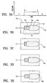
- FIGS. 3A-3E illustrated how the ink within a nozzle may react to a sub-pulse signal.
- the sub-pulse signal is typically of smaller amplitude and shorter duration than a full drop-ejecting pulse. As such, the pulse is sufficient to move the ink within the nozzle without ejecting it therefrom.
- Such a technique has been used when a printer is in a quiescent state to prevent fast drying solvent based inks from drying out and clogging the nozzle. (See for example, U.S. Pat. No.
- the present invention recognizes that allowing a fast-drying ink to dry in the nozzle forms a barrier of higher viscosity suspended solids between the nozzle orifice and the ink contained in chamber 15.
- the ink jet industry has generally tried to avoid such an effect because such a barrier would become a thick plug that would cause the nozzle to clog and operate inefficiently.
- the present invention utilizes this previously undesirable trait of fast-drying inks and uses it to a distinct advantage.
- the barrier form in such a manner as to advantageous control the evaporation of solvents within the ink.
- the result is ink within the chamber that maintains a relatively constant viscosity.
- an ink is formulated to have extremely fast-drying properties so that during the quiescent period a viscosity barrier rapidly forms at the orifice of the nozzle. Solvent and resin based inks, as described more fully below, have demonstrated the desired properties.
- Preferred ink compositions comprise a glycol ether having a low boiling point, i.e. below 150° C, preferably a glycol alkyl ether having about 3 to 20 carbon atoms, more preferably 3-7 carbon atoms, and most preferably 4 carbon atoms.
- the preferred glycol alkyl ether is propylene glycol methyl ether.
- the glycol alkyl ether comprises about 20 to 60 % by weight of the ink composition with about 44 % by weight being most preferred.
- Preferred ink compositions further comprise a ketone alcohol having about 1 to 10 carbon atoms.
- One preferred alcohol is diacetone alcohol. This component preferably comprises 20 to 60 % by weight of the ink more preferably 35 to 45 %, and most preferably about 40.6 % by weight.
- the preferred ink compositions of this invention further comprise at least one resin selected from polyester resins and acrylic resins, such as styrene acrylic resin.
- the ink composition comprises about 1 to 20 % of an alcohol soluble polyester, more preferably about 5 to 10 %, and most preferably 6.3 %.
- One preferred alcohol soluble polyester is Prince 5180, manufactured by Lawter International, Northbrook, I11.
- the ink composition preferably comprises about 1 to 10 % of a styrene acrylic polymer, more preferably 1 to 3 %, with 1.7 % being the most preferred.
- One preferred styrene acrylic polymer is Joncryl 678, available from S.C. Johnson & Son, Inc.
- Preferred ink compositions also comprise a colorant.
- the choice of colorant and its concentration principally depend on the solubility of the colorant and the intensity of its color for a particular application.
- the colorant is selected to render the ink composition visible to the human eye or some mechanical data collection device, such as a bar code scanner or other type of optical character reader.
- a preferred colorant comprises a dye such as Orasol Black RLI, which is available from Ciba-Geigy Co. of Ardsley, N.Y.
- the ink composition of this invention may further comprise one or more of the ink additives known in the art, so long as incorporation of the additives does not change the key drying properties as described in further detail below.
- the ink composition is selected so that a viscosity barrier of suspended solids, and which may actually become a solid, is allowed to form over the orifice of the nozzle during quiescent periods that exceeds predetermined time period, which is selected based on the ink formulation and other factors. Thereafter, when printing is requested, sub-pulsing is activated before printing can resume to remove the viscosity barrier by re-homogenizing it with fresh ink. While not wishing to be bound by any particular theory, it is believed that the theoretical explanation for the operation of the viscosity barrier is as described in further detail below.
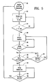
- the preferred sequence of steps to employ the viscosity barrier and the sub-pulsing are shown in the flow chart of Figure 5.
- the startup sequence begins whenever a nozzle has been idle for an extended period of time (step 20).
- nozzle 12 is sub-pulsed for a predetermined period.
- the sub-pulses have a pulse width of about 1.5 ⁇ seconds and have a frequency of about 5 kHz (step 22).
- the sub-pulse amplitude is selected to move the ink yet insufficient to eject the ink from nozzle 12.
- the particular sub-pulse parameters were selected to operate effectively with the preferred ink. Other parameters may be substituted and produce similar results, particularly where the ink formulation is different from the preferred ink disclosed herein.
- the predetermined period of sub-pulsing time is the time required to ensure that the ink in the nozzle is re-homogenized with fresh ink from the chamber. It has been determined that 5 seconds is sufficient time to break-down the viscosity barrier that is formed by the preferred ink formulation described above. Of course, other re-homogenization periods could be used depending on the particular characteristics of the ink selected and the quality of operation desired.
- the print function of the nozzle is enabled (step 26). The nozzle is then available to eject droplets on demand until printing is complete and returns to a quiescent state (step 28).
- control signals as in the present invention by modulating the amplitude of applied electric energy
- other fast drying inks using completely different formulations could be used, so long as they exhibit the desired fast-drying properties.
Landscapes
- Chemical & Material Sciences (AREA)
- Life Sciences & Earth Sciences (AREA)
- Engineering & Computer Science (AREA)
- Materials Engineering (AREA)
- Wood Science & Technology (AREA)
- Organic Chemistry (AREA)
- Ink Jet (AREA)
- Inks, Pencil-Leads, Or Crayons (AREA)
- Particle Formation And Scattering Control In Inkjet Printers (AREA)
Claims (6)
- Impulstintenstrahldrucker, aufweisend:dadurch gekennzeichnet, dass die vorbestimmte Zeitdauer so gewählt ist, dass sie ausreichend ist, eine Barriere hoch viskoser Tinte an der Öffnung zu bilden, wobei die Subauslösesignale Amplituden aufweisen, welche wirksam sind, um die Barriere von der Öffnung zu entfernen, doch welche unwirksam sind, Tintentröpfchen aus ihr auszustoßen; und dass die Steuermittel vorgesehen sind, um nach der Erzeugung von Subauslösesignalen für eine zweite Zeitdauer eine Vielzahl von Auslösesignalen zu erzeugen, wobei die Auslösesignale Amplituden aufweisen, die wirksam sind, um Tintentröpfchen aus der Düse (12) auszustoßen.mindestens eine Düse (12) mit einer Öffnung zum Ausstoßen von Tintentröpfchen (14c) als Antwort auf eine Sequenz von Steuersignalen, wobei die Sequenz Auslösesignale und Subauslösesignale aufweist;eine Kammer (15) zur Aufnahme einer Tinte in Fluidverbindung mit der Öffnung, wobei die Tinte eine chemische Lösungsmittelbasis und eine Konzentration von Feststoffen aufweist, so dass das Lösungsmittel verdunstet und eine Barriere hoher Viskosität an der Öffnung bildet, wenn die Düse in einem Ruhezustand ist;Steuermittel (16) zur Erzeugung der Sequenz von Steuersignalen und zum Steuern der Amplitude der Steuersignale, wobeidie Steuermittel (16) vorgesehen sind, um eine Vielzahl von Subauslösesignalen nach einer vorbestimmten Ruhezeitdauer zu bilden, in welcher das Subauslösen minimal ist,
- Drucker nach Anspruch 1, wobei die zweite vorbestimmte Zeitdauer die Zeit ist, welche ausreichend ist, um die Viskositätsbarriere mit frischer Tinte zu rehomogenisieren.
- Drucker nach Anspruch 1 oder 2, wobei die zweite vorbestimmte Zeitdauer ungefähr 5 Sekunden beträgt.
- Verfahren zum Betrieb eines Impulstintenstrahldruckers mit mindestens einer Düse (12), die Schritte aufweisend:wobei der Schritt des Erzeugens einer Vielzahl von Subpulsen nach einer vorbestimmten Ruhezeitdauer und vor dem Schritt des Erzeugens einer Vielzahl von Auslösesignalen durchgeführt wird,Luftexposition eines Teils der Tinte, welche in der Düse (12) enthalten ist, so dass sich eine Barriere höherer Viskosität in der Tinte bildet; Erzeugen einer Vielzahl von Subauslösesignalen, wobei die Subauslösesignale Amplituden haben, welche wirksam sind, um die Barriere zu entfernen, doch welche unwirksam sind, um Tintentröpfchen auszustoßen; undErzeugen einer Vielzahl von Auslösesignalen, wobei die Auslösesignale Amplituden haben, welche wirksam sind, um Tintentröpfchen (14c) aus der Düse (12) auszustoßen,
und wobei die vorbestimmte Ruhezeitdauer so gewählt ist, dass sie zur Bildung der Barriere ausreichend ist. - Verfahren nach Anspruch 4, wobei der Schritt des Erzeugens einer Vielzahl von Subpulsen mindestens fortdauert bis die. Barriere im wesentlichen mit der Tinte in der Düse (12) rehomogenisiert wurde.
- Verfahren nach Anspruch 4 oder 5, wobei der Schritt des Erzeugens einer Vielzahl von Subpulsen mindestens ungefähr 5 Sekunden fortdauert.
Priority Applications (2)
| Application Number | Priority Date | Filing Date | Title |
|---|---|---|---|
| EP04012273A EP1457338B1 (de) | 1997-07-31 | 1998-07-15 | Verfahren und Gerät zur Verhinderung von Verstopfung der Tintenstrahldruckerdüsen |
| EP04012274A EP1457339B1 (de) | 1997-07-31 | 1998-07-15 | Tintenzusammensetzung |
Applications Claiming Priority (3)
| Application Number | Priority Date | Filing Date | Title |
|---|---|---|---|
| US08/903,016 US20020001014A1 (en) | 1997-07-31 | 1997-07-31 | Methods and apparatus for ink capping ink jet printer nozzles |
| US903016 | 1997-07-31 | ||
| PCT/US1998/014574 WO1999006213A1 (en) | 1997-07-31 | 1998-07-15 | Methods and apparatus for ink capping ink jet printer nozzles |
Related Child Applications (4)
| Application Number | Title | Priority Date | Filing Date |
|---|---|---|---|
| EP04012273A Division EP1457338B1 (de) | 1997-07-31 | 1998-07-15 | Verfahren und Gerät zur Verhinderung von Verstopfung der Tintenstrahldruckerdüsen |
| EP04012274A Division EP1457339B1 (de) | 1997-07-31 | 1998-07-15 | Tintenzusammensetzung |
| EP04012274.9 Division-Into | 2004-05-25 | ||
| EP04012273.1 Division-Into | 2004-05-25 |
Publications (3)
| Publication Number | Publication Date |
|---|---|
| EP0998392A4 EP0998392A4 (de) | 2000-05-10 |
| EP0998392A1 EP0998392A1 (de) | 2000-05-10 |
| EP0998392B1 true EP0998392B1 (de) | 2005-11-16 |
Family
ID=25416789
Family Applications (3)
| Application Number | Title | Priority Date | Filing Date |
|---|---|---|---|
| EP98935656A Expired - Lifetime EP0998392B1 (de) | 1997-07-31 | 1998-07-15 | Verfahren und gerät zum tintendichten abdecken von tintenstrahldruckerdüsen |
| EP04012274A Expired - Lifetime EP1457339B1 (de) | 1997-07-31 | 1998-07-15 | Tintenzusammensetzung |
| EP04012273A Expired - Lifetime EP1457338B1 (de) | 1997-07-31 | 1998-07-15 | Verfahren und Gerät zur Verhinderung von Verstopfung der Tintenstrahldruckerdüsen |
Family Applications After (2)
| Application Number | Title | Priority Date | Filing Date |
|---|---|---|---|
| EP04012274A Expired - Lifetime EP1457339B1 (de) | 1997-07-31 | 1998-07-15 | Tintenzusammensetzung |
| EP04012273A Expired - Lifetime EP1457338B1 (de) | 1997-07-31 | 1998-07-15 | Verfahren und Gerät zur Verhinderung von Verstopfung der Tintenstrahldruckerdüsen |
Country Status (9)
| Country | Link |
|---|---|
| US (1) | US20020001014A1 (de) |
| EP (3) | EP0998392B1 (de) |
| JP (1) | JP2001512707A (de) |
| AT (3) | ATE309910T1 (de) |
| AU (1) | AU8485298A (de) |
| CA (1) | CA2296326C (de) |
| DE (3) | DE69834445T2 (de) |
| IL (2) | IL134126A0 (de) |
| WO (1) | WO1999006213A1 (de) |
Families Citing this family (3)
| Publication number | Priority date | Publication date | Assignee | Title |
|---|---|---|---|---|
| US6302536B1 (en) * | 1997-07-31 | 2001-10-16 | Trident International, Inc. | Fast drying ink jet ink compositions for capping ink jet printer nozzles |
| US6444019B1 (en) | 1998-11-06 | 2002-09-03 | Videojet Technologies Inc. | Ink jet ink composition |
| US6726756B1 (en) | 2000-05-26 | 2004-04-27 | Videojet Technologies Inc. | Continuous ink jet printing ink composition |
Family Cites Families (12)
| Publication number | Priority date | Publication date | Assignee | Title |
|---|---|---|---|---|
| US3925789A (en) | 1971-12-16 | 1975-12-09 | Casio Computer Co Ltd | Ink jet recording apparatus |
| JPS51137506A (en) * | 1975-05-22 | 1976-11-27 | Konishiroku Photo Ind | Composition of ink for ink jet recording |
| US4266232A (en) | 1979-06-29 | 1981-05-05 | International Business Machines Corporation | Voltage modulated drop-on-demand ink jet method and apparatus |
| DE3115532A1 (de) * | 1980-04-17 | 1982-01-28 | Canon K.K., Tokyo | Tintenstrahl-aufzeichnungsverfahren und aufzeichnungstinte fuer die aufzeichnung auf einem bildempfangsmaterial |
| US4459601A (en) | 1981-01-30 | 1984-07-10 | Exxon Research And Engineering Co. | Ink jet method and apparatus |
| US4540997A (en) | 1984-03-26 | 1985-09-10 | Tektronix, Inc. | Method and apparatus for avoiding the drying of ink in the ink jets of ink jet printers |
| US4791165A (en) * | 1985-07-18 | 1988-12-13 | Hewlett-Packard Company | Ink-jet ink for plain paper printing |
| US4970527A (en) | 1988-12-02 | 1990-11-13 | Spectra-Physics, Incorporated | Priming method for inkjet printers |
| US5160535A (en) * | 1991-01-11 | 1992-11-03 | Trident, Inc. | Rapidly drying impulse ink jet ink compositions |
| US5154761A (en) * | 1991-01-28 | 1992-10-13 | Trident, Inc. | High definition impulse ink jet in compositions |
| US5329293A (en) * | 1991-04-15 | 1994-07-12 | Trident | Methods and apparatus for preventing clogging in ink jet printers |
| JP3123195B2 (ja) * | 1992-04-15 | 2001-01-09 | ミノルタ株式会社 | インクジェット用記録液 |
-
1997
- 1997-07-31 US US08/903,016 patent/US20020001014A1/en not_active Abandoned
-
1998
- 1998-07-15 EP EP98935656A patent/EP0998392B1/de not_active Expired - Lifetime
- 1998-07-15 EP EP04012274A patent/EP1457339B1/de not_active Expired - Lifetime
- 1998-07-15 JP JP2000505004A patent/JP2001512707A/ja active Pending
- 1998-07-15 DE DE69834445T patent/DE69834445T2/de not_active Expired - Fee Related
- 1998-07-15 IL IL13412698A patent/IL134126A0/xx active IP Right Grant
- 1998-07-15 AT AT98935656T patent/ATE309910T1/de not_active IP Right Cessation
- 1998-07-15 CA CA002296326A patent/CA2296326C/en not_active Expired - Fee Related
- 1998-07-15 DE DE69832385T patent/DE69832385T2/de not_active Expired - Fee Related
- 1998-07-15 AT AT04012274T patent/ATE324985T1/de not_active IP Right Cessation
- 1998-07-15 AU AU84852/98A patent/AU8485298A/en not_active Abandoned
- 1998-07-15 WO PCT/US1998/014574 patent/WO1999006213A1/en active IP Right Grant
- 1998-07-15 DE DE69836233T patent/DE69836233D1/de not_active Expired - Lifetime
- 1998-07-15 EP EP04012273A patent/EP1457338B1/de not_active Expired - Lifetime
- 1998-07-15 AT AT04012273T patent/ATE342805T1/de not_active IP Right Cessation
-
2000
- 2000-01-19 IL IL134126A patent/IL134126A/en not_active IP Right Cessation
Also Published As
| Publication number | Publication date |
|---|---|
| DE69832385T2 (de) | 2006-06-01 |
| ATE324985T1 (de) | 2006-06-15 |
| IL134126A (en) | 2006-10-05 |
| ATE309910T1 (de) | 2005-12-15 |
| US20020001014A1 (en) | 2002-01-03 |
| EP0998392A4 (de) | 2000-05-10 |
| DE69832385D1 (de) | 2005-12-22 |
| ATE342805T1 (de) | 2006-11-15 |
| DE69834445D1 (de) | 2006-06-08 |
| DE69836233D1 (de) | 2006-11-30 |
| DE69834445T2 (de) | 2006-09-14 |
| WO1999006213A1 (en) | 1999-02-11 |
| CA2296326A1 (en) | 1999-02-11 |
| IL134126A0 (en) | 2001-04-30 |
| EP0998392A1 (de) | 2000-05-10 |
| EP1457338A1 (de) | 2004-09-15 |
| JP2001512707A (ja) | 2001-08-28 |
| AU8485298A (en) | 1999-02-22 |
| EP1457339B1 (de) | 2006-05-03 |
| CA2296326C (en) | 2004-01-20 |
| EP1457339A1 (de) | 2004-09-15 |
| EP1457338B1 (de) | 2006-10-18 |
Similar Documents
| Publication | Publication Date | Title |
|---|---|---|
| EP1059340B1 (de) | Schnelltrocknende Tintenstrahl-Tintenzusammensetzungen zum Abdichten von Tintenstrahldruckerdüsen | |
| US4266232A (en) | Voltage modulated drop-on-demand ink jet method and apparatus | |
| US5065167A (en) | Vaporizable solid ink composition for thermal ink-jet printing | |
| GB2159465A (en) | Generating droplets by heating | |
| JPH0929996A (ja) | インクジェット記録方法 | |
| JPS63235382A (ja) | インク組成物 | |
| EP0998392B1 (de) | Verfahren und gerät zum tintendichten abdecken von tintenstrahldruckerdüsen | |
| JP3671998B2 (ja) | インクジェット式記録装置 | |
| JPH0930007A (ja) | インクジェット式記録装置 | |
| WO2006107494A1 (en) | Inkjet ink for porous and non-porous printing | |
| RU95105713A (ru) | Способ струйной печати и струйная печатающая головка для его осуществления | |
| US6357852B1 (en) | Method and apparatus for restoring an ink jet printhead | |
| EP1038677A1 (de) | Verfahren und Vorrichtung zur Entstopfung eines Tintenstrahldruckkopfes | |
| JPH07148934A (ja) | インクジェット印刷ヘッドの整備方法 | |
| US5710581A (en) | Inkjet printhead having intermittent nozzle clearing | |
| JP3095905B2 (ja) | 目詰まり防止機構 | |
| JP3291490B2 (ja) | 目詰まり防止機構 | |
| JPH08169124A (ja) | インクジェット記録装置 | |
| JP3103590B2 (ja) | インクジェット記録装置および該装置における記録方法 | |
| JPH03256749A (ja) | インクジェット記録装置 | |
| JPS58167170A (ja) | インクジエツト記録装置 | |
| JPS61149359A (ja) | インクジエツト記録装置 | |
| US20030010231A1 (en) | Multi-purpose printer device | |
| JP2000094658A (ja) | 印字装置 | |
| JP2005028767A (ja) | インクジェット記録ヘッドの回復方法およびインクジェット記録装置 |
Legal Events
| Date | Code | Title | Description |
|---|---|---|---|
| PUAI | Public reference made under article 153(3) epc to a published international application that has entered the european phase |
Free format text: ORIGINAL CODE: 0009012 |
|
| 17P | Request for examination filed |
Effective date: 20000131 |
|
| A4 | Supplementary search report drawn up and despatched |
Effective date: 20000329 |
|
| AK | Designated contracting states |
Kind code of ref document: A4 Designated state(s): AT BE CH CY DE DK ES FI FR GB GR IE IT LI LU MC NL PT SE Kind code of ref document: A1 Designated state(s): AT CH DE ES FI FR GB IE IT LI NL SE |
|
| RIC1 | Information provided on ipc code assigned before grant |
Free format text: 7B 41J 2/165 A, 7B 41J 2/05 B, 7C 09D 11/00 B |
|
| RBV | Designated contracting states (corrected) |
Designated state(s): AT CH DE ES FI FR GB IE IT LI NL SE |
|
| 17Q | First examination report despatched |
Effective date: 20040324 |
|
| GRAP | Despatch of communication of intention to grant a patent |
Free format text: ORIGINAL CODE: EPIDOSNIGR1 |
|
| GRAS | Grant fee paid |
Free format text: ORIGINAL CODE: EPIDOSNIGR3 |
|
| GRAA | (expected) grant |
Free format text: ORIGINAL CODE: 0009210 |
|
| RAP1 | Party data changed (applicant data changed or rights of an application transferred) |
Owner name: ILLINOIS TOOL WORKS INC. |
|
| AK | Designated contracting states |
Kind code of ref document: B1 Designated state(s): AT CH DE ES FI FR GB IE IT LI NL SE |
|
| PG25 | Lapsed in a contracting state [announced via postgrant information from national office to epo] |
Ref country code: NL Free format text: LAPSE BECAUSE OF FAILURE TO SUBMIT A TRANSLATION OF THE DESCRIPTION OR TO PAY THE FEE WITHIN THE PRESCRIBED TIME-LIMIT Effective date: 20051116 Ref country code: LI Free format text: LAPSE BECAUSE OF FAILURE TO SUBMIT A TRANSLATION OF THE DESCRIPTION OR TO PAY THE FEE WITHIN THE PRESCRIBED TIME-LIMIT Effective date: 20051116 Ref country code: FI Free format text: LAPSE BECAUSE OF FAILURE TO SUBMIT A TRANSLATION OF THE DESCRIPTION OR TO PAY THE FEE WITHIN THE PRESCRIBED TIME-LIMIT Effective date: 20051116 Ref country code: CH Free format text: LAPSE BECAUSE OF FAILURE TO SUBMIT A TRANSLATION OF THE DESCRIPTION OR TO PAY THE FEE WITHIN THE PRESCRIBED TIME-LIMIT Effective date: 20051116 Ref country code: AT Free format text: LAPSE BECAUSE OF FAILURE TO SUBMIT A TRANSLATION OF THE DESCRIPTION OR TO PAY THE FEE WITHIN THE PRESCRIBED TIME-LIMIT Effective date: 20051116 |
|
| REG | Reference to a national code |
Ref country code: GB Ref legal event code: FG4D |
|
| REG | Reference to a national code |
Ref country code: CH Ref legal event code: EP |
|
| REG | Reference to a national code |
Ref country code: IE Ref legal event code: FG4D |
|
| REF | Corresponds to: |
Ref document number: 69832385 Country of ref document: DE Date of ref document: 20051222 Kind code of ref document: P |
|
| PG25 | Lapsed in a contracting state [announced via postgrant information from national office to epo] |
Ref country code: SE Free format text: LAPSE BECAUSE OF FAILURE TO SUBMIT A TRANSLATION OF THE DESCRIPTION OR TO PAY THE FEE WITHIN THE PRESCRIBED TIME-LIMIT Effective date: 20060216 |
|
| PG25 | Lapsed in a contracting state [announced via postgrant information from national office to epo] |
Ref country code: ES Free format text: LAPSE BECAUSE OF FAILURE TO SUBMIT A TRANSLATION OF THE DESCRIPTION OR TO PAY THE FEE WITHIN THE PRESCRIBED TIME-LIMIT Effective date: 20060227 |
|
| NLV1 | Nl: lapsed or annulled due to failure to fulfill the requirements of art. 29p and 29m of the patents act | ||
| REG | Reference to a national code |
Ref country code: CH Ref legal event code: PL |
|
| PG25 | Lapsed in a contracting state [announced via postgrant information from national office to epo] |
Ref country code: IE Free format text: LAPSE BECAUSE OF NON-PAYMENT OF DUE FEES Effective date: 20060717 |
|
| ET | Fr: translation filed | ||
| PLBE | No opposition filed within time limit |
Free format text: ORIGINAL CODE: 0009261 |
|
| STAA | Information on the status of an ep patent application or granted ep patent |
Free format text: STATUS: NO OPPOSITION FILED WITHIN TIME LIMIT |
|
| 26N | No opposition filed |
Effective date: 20060817 |
|
| REG | Reference to a national code |
Ref country code: IE Ref legal event code: MM4A |
|
| PGFP | Annual fee paid to national office [announced via postgrant information from national office to epo] |
Ref country code: DE Payment date: 20070831 Year of fee payment: 10 |
|
| PGFP | Annual fee paid to national office [announced via postgrant information from national office to epo] |
Ref country code: GB Payment date: 20070727 Year of fee payment: 10 |
|
| PGFP | Annual fee paid to national office [announced via postgrant information from national office to epo] |
Ref country code: IT Payment date: 20070726 Year of fee payment: 10 |
|
| PGFP | Annual fee paid to national office [announced via postgrant information from national office to epo] |
Ref country code: FR Payment date: 20070717 Year of fee payment: 10 |
|
| GBPC | Gb: european patent ceased through non-payment of renewal fee |
Effective date: 20080715 |
|
| PG25 | Lapsed in a contracting state [announced via postgrant information from national office to epo] |
Ref country code: DE Free format text: LAPSE BECAUSE OF NON-PAYMENT OF DUE FEES Effective date: 20090203 |
|
| REG | Reference to a national code |
Ref country code: FR Ref legal event code: ST Effective date: 20090331 |
|
| PG25 | Lapsed in a contracting state [announced via postgrant information from national office to epo] |
Ref country code: GB Free format text: LAPSE BECAUSE OF NON-PAYMENT OF DUE FEES Effective date: 20080715 |
|
| PG25 | Lapsed in a contracting state [announced via postgrant information from national office to epo] |
Ref country code: IT Free format text: LAPSE BECAUSE OF NON-PAYMENT OF DUE FEES Effective date: 20080715 Ref country code: FR Free format text: LAPSE BECAUSE OF NON-PAYMENT OF DUE FEES Effective date: 20080731 |