EP0997655B1 - Guide linéaire - Google Patents
Guide linéaire Download PDFInfo
- Publication number
- EP0997655B1 EP0997655B1 EP99119655A EP99119655A EP0997655B1 EP 0997655 B1 EP0997655 B1 EP 0997655B1 EP 99119655 A EP99119655 A EP 99119655A EP 99119655 A EP99119655 A EP 99119655A EP 0997655 B1 EP0997655 B1 EP 0997655B1
- Authority
- EP
- European Patent Office
- Prior art keywords
- groove
- linear guide
- guide according
- base
- hollow section
- Prior art date
- Legal status (The legal status is an assumption and is not a legal conclusion. Google has not performed a legal analysis and makes no representation as to the accuracy of the status listed.)
- Expired - Lifetime
Links
Images


Classifications
-
- F—MECHANICAL ENGINEERING; LIGHTING; HEATING; WEAPONS; BLASTING
- F16—ENGINEERING ELEMENTS AND UNITS; GENERAL MEASURES FOR PRODUCING AND MAINTAINING EFFECTIVE FUNCTIONING OF MACHINES OR INSTALLATIONS; THERMAL INSULATION IN GENERAL
- F16C—SHAFTS; FLEXIBLE SHAFTS; ELEMENTS OR CRANKSHAFT MECHANISMS; ROTARY BODIES OTHER THAN GEARING ELEMENTS; BEARINGS
- F16C29/00—Bearings for parts moving only linearly
- F16C29/12—Arrangements for adjusting play
-
- B—PERFORMING OPERATIONS; TRANSPORTING
- B25—HAND TOOLS; PORTABLE POWER-DRIVEN TOOLS; MANIPULATORS
- B25J—MANIPULATORS; CHAMBERS PROVIDED WITH MANIPULATION DEVICES
- B25J15/00—Gripping heads and other end effectors
- B25J15/02—Gripping heads and other end effectors servo-actuated
- B25J15/0253—Gripping heads and other end effectors servo-actuated comprising parallel grippers
- B25J15/0266—Gripping heads and other end effectors servo-actuated comprising parallel grippers actuated by articulated links
- B25J15/0273—Gripping heads and other end effectors servo-actuated comprising parallel grippers actuated by articulated links comprising linear guide means
-
- F—MECHANICAL ENGINEERING; LIGHTING; HEATING; WEAPONS; BLASTING
- F16—ENGINEERING ELEMENTS AND UNITS; GENERAL MEASURES FOR PRODUCING AND MAINTAINING EFFECTIVE FUNCTIONING OF MACHINES OR INSTALLATIONS; THERMAL INSULATION IN GENERAL
- F16C—SHAFTS; FLEXIBLE SHAFTS; ELEMENTS OR CRANKSHAFT MECHANISMS; ROTARY BODIES OTHER THAN GEARING ELEMENTS; BEARINGS
- F16C29/00—Bearings for parts moving only linearly
- F16C29/04—Ball or roller bearings
-
- F—MECHANICAL ENGINEERING; LIGHTING; HEATING; WEAPONS; BLASTING
- F16—ENGINEERING ELEMENTS AND UNITS; GENERAL MEASURES FOR PRODUCING AND MAINTAINING EFFECTIVE FUNCTIONING OF MACHINES OR INSTALLATIONS; THERMAL INSULATION IN GENERAL
- F16C—SHAFTS; FLEXIBLE SHAFTS; ELEMENTS OR CRANKSHAFT MECHANISMS; ROTARY BODIES OTHER THAN GEARING ELEMENTS; BEARINGS
- F16C33/00—Parts of bearings; Special methods for making bearings or parts thereof
- F16C33/30—Parts of ball or roller bearings
- F16C33/58—Raceways; Race rings
- F16C33/60—Raceways; Race rings divided or split, e.g. comprising two juxtaposed rings
- F16C33/61—Raceways; Race rings divided or split, e.g. comprising two juxtaposed rings formed by wires
Definitions
- the invention relates to a linear guide, with a base body, one base and two below the side a groove-like depression of the base projecting leg having at least one in the groove-like depression engaging, relative to the main body in the longitudinal direction of groove-like recess movable runners, and with inside the groove-like depression between the runner and this flanking legs acting guide means, wherein between the two legs of the body acting clamping means are present, which is an elastic deformation of the Legs with respect to the base allow in the area of Guide means a variable adjustment of the width of the groove-like To be able to do well.
- a resulting from US-A-5657973 linear guide is Bestanzteil a fluid-operated gripper.
- the case of the Gripper which is a driven by fluid power drive means contains, forms a basic body with two parallel arranged thighs, one in cross-section For example, limit T-shaped groove-like depression.
- gripping element carrier linear slidably guided by the drive means can be caused to an opposing linear motion, handling work by means of gripping elements fixed thereto perform.
- the linear guide is particularly suitable for use with fluid operated grippers to guide the Runners forming gripping elements or gripping element carrier opposite the housing of the gripper, but is also in the readily Can be used in conjunction with other products that come with a Linear guide are equipped.
- deformation grooves are the basic body in the field of Thighs locally weakening with the structure of the main body Provided grooves, hereinafter referred to as deformation grooves are.
- deformation grooves are the basic body in the field of Thighs locally weakening with the structure of the main body Provided grooves, hereinafter referred to as deformation grooves are.
- deformation grooves are in the range of one and preferably both legs one provided as a longitudinal groove running deformation, which is extends parallel to the longitudinal axis of the groove-like depression. It can be particularly in the transition area between the respective leg and the base of the body are located.
- the clamping means are expediently at least partially formed by clamping elements in or on the two legs are anchored and the groove-like depressions web-like traverse. This is expediently around Clamping screws, which are supported with their head on one leg while they are with their threaded shank in the other legs are screwed.
- each deformation section assigned its own clamping device can be a very individual and sensitive attitude of the guiding game, taking care of the settings not mutually or at least only slightly influence.
- each leg one Assigned arrangement of deformation grooves in which it is a combination of longitudinal grooves and transverse grooves, which can also merge into each other.
- the guide means may for example be designed so that results in a sliding guide, wherein the guide means facing each other and in contact with each other Side surfaces of the rotor and the legs may be formed. Especially when higher lateral loads occur, offers However, the design as Wälz Entry.
- the linear guide may preferably be designed in this way be that the guide means on each side of the runner over have at least one leadership unit, the one on the main body fixed first support body and one on the runner fixed second support body, each supporting body at least one and expediently two parallel next to each other arranged and each a rolling surface carrying defining rod-shaped bearing elements, and wherein between the support bodies a fitting to the bearing elements Rolling element arrangement is provided.
- the support bodies exist here expediently of plastic material while you as bearing elements preferably components made of hardened steel used.
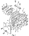
- Fluid operated gripper has a housing 2 with a For example, cuboid middle part 3, at the two axial end faces end cover 4, 4 'are attached.
- the middle part 3 forms a main body 5 of a general denoted by reference numeral 6 linear guide, the principalsbeipiel also two as runners 7, 7 'designated Contains components that of the gripper element holders 8, 8 'of the Gripper 1 are formed.
- About guide means 12 are the Runners 7, 7 'on the base body 5 in the direction of its longitudinal axis 13 slidably guided and simultaneously in the transverse direction supported.
- the gripper element carrier 8, 8 ' are in the longitudinal direction of the housing 2 consecutively arranged and stand each with a housed in the housing 2 and indicated only schematically fluid actuated drive device 14 in drive connection.
- the structure of the drive device 14 may, for example the same as in US 5,657,973 is explained. It can be two with each one of the Gripping element carrier 8, 8 'movement-coupled driver 15th containing the fluid force induced axial movement two pistons of the drive device 14 on the gripper element carrier 8, 8 'transmitted. It is in particular a mode of operation possible, in which the gripper element carrier 8, 8 'a axially opposing linear movement relative to the housing.
- Gripping elements in the context of an opening or closing movement from each other or to approach each other.
- the Gripping elements which are also referred to as gripping jaws could, can be replaced via fasteners 16 to the gripping element carriers 8, 8 'fasten.
- the base body 5 formed by the central part 3 has a section referred to below as the base 17 in which housed in the embodiment, the drive device 14 is and essentially a plate or block-like Has shape.
- the two in the embodiment of the gripper element carriers 8, 8 'formed runners 7, 7' - instead of the gripper element carrier 8, 8 'could also be provided directly gripping elements be - engage in the groove-like depression 22, where they in the embodiment with a major part of her Cross-section engaging foot portion 23 in the groove-like Well 22 are included and the rest, with a Head portion 24, over the longitudinal opening 25 of the groove-like Protrude recess 22 and over the outer surface of the Projecting body 5.
- the above-mentioned guide means 12 are located inside the groove-like depression 22 and work there on both sides of a respective rotor 7, 7 'between this and the respective adjacent legs 18, 18 '.
- the one respective rotor 7, 7 'assigned Guide means 12 of two on both sides of the rotor 7, 7 ' arranged guide units 29 are made, which expediently have a later explained advantageous structure.
- the linear guide 6 also has between the two legs 18, 18 'acting clamping means 26, located in a way that an elastic deformation the legs 18, 18 'takes place relative to the base 17, wherein the width of the groove-like depression 22 changed.
- the deformation regions 28, 28 ' are expediently located in the transitional areas between the base 17 and the respective leg 18, 18 ', so that the deformation process can also be referred to as a bending process.
- the adjustment measures are designed especially for this reason particularly simple, because the legs 18, 18 'integral with the base 17 are connected and thus at a removal the clamping force automatically increasing the width of the groove-like depression 22 in the direction of its tension-free Starting position are deformed back.
- the clamping means 26 are of several rod-like clamping elements 27 formed in the two Legs 18, 18 'are anchored and the groove-like depression 22 in particular in the vicinity of the base 17 web-like traverse.
- the clamping elements 27 have the effect of tie rods and can be done in the tension sense of actuation cause the legs 18, 18 'to face each other be slightly bent elastically.
- the clamping elements 27 are clamping screws, wherein according to Figures 2 and 3 may be provided that they rest with their head 32 on one leg 18 ', while she's with her threaded shaft 33 in the other Legs are screwed.
- the clamping elements 27 extend in each case in two the legs 18, 18 'passing through and in the region of the groove-like depression 22 with each other aligned holes.
- the installation depth of the rotor 7, 7 'with respect the groove-like recess 22 is chosen so that they can run over the clamping elements 27.
- clamping elements 27 As is apparent from Figures 1 and 2, come expediently simultaneously several clamping elements 27 are used, the distributed over the length of the groove-like recess 22 at a distance are arranged and operate independently to let.
- the number of clamping elements 27 and their distribution density hangs over the length of the main body 5 away in particular of the length of the body 5 and the Guide route from.
- the Main body 5 in particular in the region of the two legs 18, 18 'provided with grooves that influence the deformation behavior, and the following in their entirety as Verformungsnuten 34 are designated.
- both legs 18, 18 'further deformation grooves 34 provided as a transverse grooves 38 are executed and which comparable to the outer Longitudinal grooves 36 in the lateral outer surfaces 35, 35 'of the Base body 5 are introduced.
- Their longitudinal course is, however in particular at right angles to that of the longitudinal grooves Directed 36, wherein they are parallel in the embodiment to the depth direction 42 of the groove-like recess 22 extend.
- the transverse grooves 38 extend only in the legs 18, 18 ', where they over as shown the entire height of the respective associated leg 18, 18 ' extend so that they one end facing away from the base 17 free end of a respective leg 18, 18 'and the other to that on the same lateral outer surface 35, 35 'provided longitudinal groove 36 are open.
- each leg 18, 18 ' has two such Transverse grooves 38.
- a respective leg 18, 18 'can deformation sections 43 form, to each of which a clamping means 26 or Clamping element 27 engages to one of the other deformation sections 43 essentially unaffected, localized Deformation of the respective leg 18, 18 make ' to be able to.
- a corresponding embodiment is the Embodiment before.
- FIG. 4 makes another advantageous use the transverse grooves 38 clearly.
- the longitudinal groove 36 associated with the front side Mouths of a respective pair of a transverse groove 38 and a Mounting hole 44 are thus aligned coaxially.
- a screw in the mounting hole 44 introduce at the same time a possibly existing head of the fastener in the lateral Outer surface 35, 35 'of the main body 5 sunk to lie comes.
- the guide units 29 could be made directly adjacent to each other abutting sliding surfaces consist of facing each other Side surfaces of the rotor 7, 7 'and the legs 18, 18 'are formed. Also, it would be conceivable to face each other Insert side surfaces groove-like depressions, in which held by cages rolling elements run, wherein they directly on the surfaces of the legs 18, 18 'and the Roll runners 7, 7 '. In the embodiment, another, realized as particularly advantageous design realized which makes it possible for the main body 5 a less To use wear-resistant material such as aluminum by the rolling surfaces 46 for a rolling element 47 at a separate Bearing elements 48 are provided.
- FIG. 1 and 4 contains a respective guide unit 29 a in the interior of the groove-like Recess 22 provided on the main body 5 first support body 52 and one opposite in the area of the facing side surface of the rotor 7, 7 'arranged second support body 53.
- the support bodies 52, 53 are expediently in longitudinal grooves the legs 18, 18 'and runners 7, 7' used to a to get compact width. They insist as well suitably made of plastic material.
- each support body 52, 53 are two longitudinal and each other provided parallel pockets, which have a slot-like Pass opening 55 in a longitudinal groove 57, which adjoin the front of the respective other support body facing of the respective supporting body is located.
- the opposing longitudinal grooves 56 of two associated define first and second support body 52, 53 a channel in which in the embodiment of rolling balls having Wälz redesignan ever 47 is housed.
- the Bearing elements 48 are rod-shaped and back the support body 52, 53 inserted into the pockets 54 and protrude with a section of its circumference through the slit-like Opening 55 in the associated longitudinal groove 56, wherein this Peripheral sections form the rolling surfaces 46, where the Rolling element 47 expires.
- the support Bearing elements 48 directly on the associated main body. 5 Runners 7,7 'from, so that the support body 52, 53 preferably are not in direct contact with these components and not be loaded in the transverse direction. They are expediently used only to receive the bearing elements 48 and to prevent their displacement in the longitudinal direction as well to exert an axial stop function with respect to the rolling elements.
- the bearing elements 48 are suitably made of hardened Steel and are very wear-resistant in this way. Furthermore
- the guide units can be mounted very easily. You can, for example, by a snap connection or through any other connection on the associated component be attached.
- a cover is still indicated, which in the embodiment the transition region between the two gripping element carriers 8, 8 'covered, in particular to penetrate to prevent contamination.
Landscapes
- Engineering & Computer Science (AREA)
- General Engineering & Computer Science (AREA)
- Mechanical Engineering (AREA)
- Robotics (AREA)
- Bearings For Parts Moving Linearly (AREA)
Claims (16)
- Guide linéaire avec un corps de base (5) qui comporte une base (17) et deux côtés (18, 18') partant de la base en délimitant latéralement un renfoncement (22) de type rainure, avec au moins un curseur (7, 7') s'engageant dans le renfoncement (22) de type rainure et déplaçable par rapport au corps de base (5) dans la direction longitudinale du renfoncement (22) de type rainure, et avec des moyens de guidage (12) agissant à l'intérieur du renfoncement (22) de type rainure entre le curseur (7, 7') et les côtés (18, 18') flanquant celui-ci, des moyens de serrage (26) agissant entre les deux côtés (18, 18'), qui permettent une déformation élastique des côtés (18, 18') par rapport à la base (17), étant prévus pour permettre de procéder, dans la zone des moyens de guidage (12), à un réglage variable de la largeur du renfoncement (22) de type rainure, caractérisé en ce que dans la zone de l'un ou des deux côtés il est prévu, sur la surface extérieure (35, 35') opposée au refoncement (22) de type rainure, du corps de base (5), une rainure longitudinale (36) s'étendant parallèlement à l'axe longitudinal du renfoncement (22) de type rainure, les moyens de serrage (26) agissant, sur le côté de la rainure longitudinale (36) opposé à la base (17), sur le côté (18, 18') concerné, de manière que la rainure longitudinale (36) soit disposée entre les moyens de serrage (26) et la base (17).
- Guide linéaire selon la revendication 1, caractérisé en ce que les côtés (18, 18') sont reliés d'une seule pièce à la base (17).
- Guide linéaire selon la revendication 1 ou 2, caractérisé en ce que les moyens de serrage (26) sont formés au moins en partie par des éléments de serrage (27) ancrés dans ou sur les deux côtés (18, 18') et traversant à la manière d'une entretoise le renfoncement (22) de type rainure.
- Guide linéaire selon la revendication 3, caractérisé en ce que les éléments de serrage (27) sont formés par des vis de serrage.
- Guide linéaire selon l'une des revendications 1 à 4, caractérisé en ce qu'il est prévu plusieurs moyens de serrage (26) répartis sur la longueur du renfoncement (22) de type rainure et disposés à distance les uns des autres, qui peuvent être actionnés en particulier indépendamment les uns des autres.
- Guide linéaire selon l'une des revendications 1 à 5, caractérisé en ce que la rainure longitudinale (36) se trouve dans la zone de transition entre le côté (18, 18') concerné et la base (17).
- Guide linéaire selon l'une des revendications 1 à 6, caractérisé en ce que dans la zone d'un ou de plusieurs côtés (18, 18') il est prévu, sur la surface extérieure (35, 35') du corps de base (5), opposée au renfoncement (22) de type rainure, au moins une rainure transversale (38) s'étendant parallèlement à la direction de la profondeur (42) du renfoncement (22) de type rainure.
- Guide linéaire selon la revendication 7, caractérisé en ce que le côté (18, 18') concerné présente plusieurs rainures transversales (38), disposées, dans sa direction longitudinale, à distance les unes des autres.
- Guide linéaire selon la revendication 7 ou 8, caractérisé en ce que le côté concerné est divisé par la au moins une rainure transversale en plusieurs tronçons de déformation (43), sur chacun desquels agit au moins un moyen de serrage (26).
- Guide linéaire selon l'une des revendications 7 à 9, caractérisé en ce que les rainures transversales (38) rencontrent chacune une rainure longitudinale (36).
- Guide linéaire selon l'une des revendications 7 à 10, caractérisé en ce que les rainures transversales (38) s'étendent sur toute la hauteur du côté (18, 18') associé.
- Guide linéaire selon l'une des revendications 7 à 11, caractérisé en ce qu'au moins une rainure transversale (38) est ouverte vers l'extrémité libre du côté (18, 18') associé, l'embouchure d'un perçage de fixation traversant la base (17) faisant face à l'extrémité, tournée à l'opposé de la base (17), de cette rainure transversale (38).
- Guide linéaire selon l'une des revendications 1 à 12, caractérisé en ce que les moyens de guidage (12) disposent, sur chaque côté du curseur (7, 7'), d'au moins une unité de guidage (29) qui contient un premier corps de support (52), associé au corps de base (5), et un deuxième corps de support (53) associé au curseur (7, 7'), chaque corps de support (52, 53) portant au moins un élément d'appui (48) de type barrette définissant une surface de roulement (46), et un agencement de corps de roulement (47), s'appliquant contre les éléments d'appui (48), étant prévu entre les corps de support (52, 53) de chaque unité de guidage (29).
- Guide linéaire selon la revendication 13, caractérisé en ce que sur chaque corps de support (52, 53) sont prévus deux éléments d'appui (48) parallèles l'un à l'autre, contre lesquels s'applique en même temps l'agencement de corps de roulement (47).
- Guide linéaire selon la revendication 13 ou 14, caractérisé en ce que les corps de support (52, 53) sont en matière synthétique, tandis que les éléments d'appui sont avantageusement en acier trempé.
- Guide linéaire selon l'une des revendications 1 à 15, caractérisé en ce que le corps de base (5) fait partie intégrante du boítier (2) d'un préhenseur (1) actionné par fluide, le au moins un curseur (7, 7') étant formé par un élément de préhension ou un support d'élément de préhension (8, 8') du préhenseur (1).
Applications Claiming Priority (2)
| Application Number | Priority Date | Filing Date | Title |
|---|---|---|---|
| DE29819265U DE29819265U1 (de) | 1998-10-29 | 1998-10-29 | Linearführung |
| DE29819265U | 1998-10-29 |
Publications (2)
| Publication Number | Publication Date |
|---|---|
| EP0997655A1 EP0997655A1 (fr) | 2000-05-03 |
| EP0997655B1 true EP0997655B1 (fr) | 2005-02-23 |
Family
ID=8064541
Family Applications (1)
| Application Number | Title | Priority Date | Filing Date |
|---|---|---|---|
| EP99119655A Expired - Lifetime EP0997655B1 (fr) | 1998-10-29 | 1999-10-04 | Guide linéaire |
Country Status (2)
| Country | Link |
|---|---|
| EP (1) | EP0997655B1 (fr) |
| DE (2) | DE29819265U1 (fr) |
Cited By (1)
| Publication number | Priority date | Publication date | Assignee | Title |
|---|---|---|---|---|
| DE202010009782U1 (de) | 2010-07-02 | 2010-09-09 | Festo Ag & Co. Kg | Greiferanordnung |
Families Citing this family (7)
| Publication number | Priority date | Publication date | Assignee | Title |
|---|---|---|---|---|
| DE19931133A1 (de) * | 1999-07-06 | 2001-01-25 | Festo Ag & Co | Verfahren zur Herstellung einer Linearführungseinrichtung |
| DE102006007068A1 (de) | 2006-02-15 | 2007-08-16 | Robert Bosch Gmbh | Linearführungseinrichtung mit Vorspannungseinstelleinrichtung |
| DE102007016436A1 (de) | 2007-04-05 | 2008-10-09 | Festo Ag & Co. Kg | Elektrisch betätigbare Greifvorrichtung |
| DE102008019582A1 (de) * | 2008-04-18 | 2009-10-22 | Robert Bosch Gmbh | Linearbewegungsvorrichtung mit Spannbolzen |
| DE102013019035B4 (de) * | 2013-11-15 | 2019-05-09 | Günther Zimmer | Greifvorrichtung mit Führungsnutdichtung |
| DE102013019034B4 (de) * | 2013-11-15 | 2019-05-09 | Günther Zimmer | Greifvorrichtung mit separaten Führungsschienen |
| DE102021203434B4 (de) | 2021-04-07 | 2023-02-09 | Festo Se & Co. Kg | Linearbewegungsvorrichtung |
Family Cites Families (4)
| Publication number | Priority date | Publication date | Assignee | Title |
|---|---|---|---|---|
| JPS59222619A (ja) * | 1983-05-30 | 1984-12-14 | Hiroshi Teramachi | 直線摺動用ベアリングの隙間調整方法 |
| DE3931397A1 (de) * | 1989-09-20 | 1991-03-28 | Star Gmbh | Waelzlager fuer linearbewegungen stichwort: schienenfuehrung mit vorspannungseinstellung |
| JP2582585Y2 (ja) * | 1993-02-25 | 1998-10-08 | 日本トムソン株式会社 | 直動転がり案内ユニット |
| DE29518242U1 (de) * | 1995-11-17 | 1996-01-11 | Isel Automation Hugo Isert | Linearführung |
-
1998
- 1998-10-29 DE DE29819265U patent/DE29819265U1/de not_active Expired - Lifetime
-
1999
- 1999-10-04 DE DE59911652T patent/DE59911652D1/de not_active Expired - Lifetime
- 1999-10-04 EP EP99119655A patent/EP0997655B1/fr not_active Expired - Lifetime
Cited By (1)
| Publication number | Priority date | Publication date | Assignee | Title |
|---|---|---|---|---|
| DE202010009782U1 (de) | 2010-07-02 | 2010-09-09 | Festo Ag & Co. Kg | Greiferanordnung |
Also Published As
| Publication number | Publication date |
|---|---|
| DE29819265U1 (de) | 1999-01-28 |
| DE59911652D1 (de) | 2005-03-31 |
| EP0997655A1 (fr) | 2000-05-03 |
Similar Documents
| Publication | Publication Date | Title |
|---|---|---|
| EP0868965B1 (fr) | Dispositif d'entraínement d'un chariot | |
| EP2977145B2 (fr) | Dispositif de serrage central | |
| EP1272409B1 (fr) | Appareil de manipulation servant a transferer des pieces | |
| EP0595074B1 (fr) | Dispositif de serrage | |
| DE102005006398B4 (de) | Vorrichtung zum Greifen und Halten eines Bauteils | |
| WO1985005586A1 (fr) | Installation de protection pour la voie de guidage de deux parties de machines entrainees et placees de maniere mobile longitudinalement l'une contre l'autre | |
| EP1197319B2 (fr) | Entraînement par coin | |
| DE112007001185B4 (de) | Einstellbarer Linearschlitten und Verfahren zum Aufbau | |
| DE3718157A1 (de) | Schraubstock | |
| EP0997655B1 (fr) | Guide linéaire | |
| DE19600314C2 (de) | Relais mit zwangsgeführten Kontaktsätzen | |
| DE102011054063B4 (de) | Antriebsvorrichtung für ein Stützteil zum Abstützen eines Werkstücks | |
| EP1577053A1 (fr) | Actionneur linéaire avec un chariot flanqué par deux unités de guidage | |
| DE3506491A1 (de) | Druckmittelbetaetigter arbeitszylinder | |
| DE3151275C2 (de) | Befestigungsvorrichtung für Werkzeuge | |
| EP3563990B1 (fr) | Dispositif de préhension à élément cunéiforme coulissant double ii optimisé | |
| DE3420857A1 (de) | Greifvorrichtung mit greiferbacke | |
| EP2998068B1 (fr) | Étau de centrage doté de mors a changement rapide | |
| EP0410115B1 (fr) | Mandrin | |
| EP1000684B1 (fr) | Dispositif de transfert pour le transport pas à pas des pièces à travailler dans une machine | |
| DE3113185C2 (de) | Anschlagsystem für die Lineareinheit eines Handhabungsgerätes | |
| EP1263546B1 (fr) | Unite d'entrainement lineaire | |
| EP0641940A2 (fr) | Dispositif de connexion pour pièces profilées | |
| DE3513214A1 (de) | Arbeitszylinder mit kugelfuehrung | |
| DE102006007771B4 (de) | Vorrichtung mit Führung und herausnehmbaren taillierten Nocken |
Legal Events
| Date | Code | Title | Description |
|---|---|---|---|
| PUAI | Public reference made under article 153(3) epc to a published international application that has entered the european phase |
Free format text: ORIGINAL CODE: 0009012 |
|
| AK | Designated contracting states |
Kind code of ref document: A1 Designated state(s): DE FR GB IT |
|
| AX | Request for extension of the european patent |
Free format text: AL;LT;LV;MK;RO;SI |
|
| 17P | Request for examination filed |
Effective date: 20000310 |
|
| AKX | Designation fees paid |
Free format text: DE FR GB IT |
|
| 17Q | First examination report despatched |
Effective date: 20031114 |
|
| GRAP | Despatch of communication of intention to grant a patent |
Free format text: ORIGINAL CODE: EPIDOSNIGR1 |
|
| GRAS | Grant fee paid |
Free format text: ORIGINAL CODE: EPIDOSNIGR3 |
|
| GRAA | (expected) grant |
Free format text: ORIGINAL CODE: 0009210 |
|
| AK | Designated contracting states |
Kind code of ref document: B1 Designated state(s): DE FR GB IT |
|
| REG | Reference to a national code |
Ref country code: GB Ref legal event code: FG4D Free format text: NOT ENGLISH |
|
| GBT | Gb: translation of ep patent filed (gb section 77(6)(a)/1977) |
Effective date: 20050223 |
|
| REF | Corresponds to: |
Ref document number: 59911652 Country of ref document: DE Date of ref document: 20050331 Kind code of ref document: P |
|
| PLBE | No opposition filed within time limit |
Free format text: ORIGINAL CODE: 0009261 |
|
| STAA | Information on the status of an ep patent application or granted ep patent |
Free format text: STATUS: NO OPPOSITION FILED WITHIN TIME LIMIT |
|
| 26N | No opposition filed |
Effective date: 20051124 |
|
| ET | Fr: translation filed | ||
| PGFP | Annual fee paid to national office [announced via postgrant information from national office to epo] |
Ref country code: GB Payment date: 20130815 Year of fee payment: 15 |
|
| PGFP | Annual fee paid to national office [announced via postgrant information from national office to epo] |
Ref country code: FR Payment date: 20131018 Year of fee payment: 15 |
|
| PGFP | Annual fee paid to national office [announced via postgrant information from national office to epo] |
Ref country code: IT Payment date: 20131004 Year of fee payment: 15 |
|
| GBPC | Gb: european patent ceased through non-payment of renewal fee |
Effective date: 20141004 |
|
| PG25 | Lapsed in a contracting state [announced via postgrant information from national office to epo] |
Ref country code: GB Free format text: LAPSE BECAUSE OF NON-PAYMENT OF DUE FEES Effective date: 20141004 |
|
| REG | Reference to a national code |
Ref country code: FR Ref legal event code: ST Effective date: 20150630 |
|
| PG25 | Lapsed in a contracting state [announced via postgrant information from national office to epo] |
Ref country code: IT Free format text: LAPSE BECAUSE OF NON-PAYMENT OF DUE FEES Effective date: 20141004 Ref country code: FR Free format text: LAPSE BECAUSE OF NON-PAYMENT OF DUE FEES Effective date: 20141031 |
|
| PGFP | Annual fee paid to national office [announced via postgrant information from national office to epo] |
Ref country code: DE Payment date: 20150929 Year of fee payment: 17 |
|
| REG | Reference to a national code |
Ref country code: DE Ref legal event code: R119 Ref document number: 59911652 Country of ref document: DE |
|
| PG25 | Lapsed in a contracting state [announced via postgrant information from national office to epo] |
Ref country code: DE Free format text: LAPSE BECAUSE OF NON-PAYMENT OF DUE FEES Effective date: 20170503 |