EP0997655B1 - Linear guide - Google Patents
Linear guide Download PDFInfo
- Publication number
- EP0997655B1 EP0997655B1 EP99119655A EP99119655A EP0997655B1 EP 0997655 B1 EP0997655 B1 EP 0997655B1 EP 99119655 A EP99119655 A EP 99119655A EP 99119655 A EP99119655 A EP 99119655A EP 0997655 B1 EP0997655 B1 EP 0997655B1
- Authority
- EP
- European Patent Office
- Prior art keywords
- groove
- linear guide
- guide according
- base
- hollow section
- Prior art date
- Legal status (The legal status is an assumption and is not a legal conclusion. Google has not performed a legal analysis and makes no representation as to the accuracy of the status listed.)
- Expired - Lifetime
Links
Images


Classifications
-
- F—MECHANICAL ENGINEERING; LIGHTING; HEATING; WEAPONS; BLASTING
- F16—ENGINEERING ELEMENTS AND UNITS; GENERAL MEASURES FOR PRODUCING AND MAINTAINING EFFECTIVE FUNCTIONING OF MACHINES OR INSTALLATIONS; THERMAL INSULATION IN GENERAL
- F16C—SHAFTS; FLEXIBLE SHAFTS; ELEMENTS OR CRANKSHAFT MECHANISMS; ROTARY BODIES OTHER THAN GEARING ELEMENTS; BEARINGS
- F16C29/00—Bearings for parts moving only linearly
- F16C29/12—Arrangements for adjusting play
-
- B—PERFORMING OPERATIONS; TRANSPORTING
- B25—HAND TOOLS; PORTABLE POWER-DRIVEN TOOLS; MANIPULATORS
- B25J—MANIPULATORS; CHAMBERS PROVIDED WITH MANIPULATION DEVICES
- B25J15/00—Gripping heads and other end effectors
- B25J15/02—Gripping heads and other end effectors servo-actuated
- B25J15/0253—Gripping heads and other end effectors servo-actuated comprising parallel grippers
- B25J15/0266—Gripping heads and other end effectors servo-actuated comprising parallel grippers actuated by articulated links
- B25J15/0273—Gripping heads and other end effectors servo-actuated comprising parallel grippers actuated by articulated links comprising linear guide means
-
- F—MECHANICAL ENGINEERING; LIGHTING; HEATING; WEAPONS; BLASTING
- F16—ENGINEERING ELEMENTS AND UNITS; GENERAL MEASURES FOR PRODUCING AND MAINTAINING EFFECTIVE FUNCTIONING OF MACHINES OR INSTALLATIONS; THERMAL INSULATION IN GENERAL
- F16C—SHAFTS; FLEXIBLE SHAFTS; ELEMENTS OR CRANKSHAFT MECHANISMS; ROTARY BODIES OTHER THAN GEARING ELEMENTS; BEARINGS
- F16C29/00—Bearings for parts moving only linearly
- F16C29/04—Ball or roller bearings
-
- F—MECHANICAL ENGINEERING; LIGHTING; HEATING; WEAPONS; BLASTING
- F16—ENGINEERING ELEMENTS AND UNITS; GENERAL MEASURES FOR PRODUCING AND MAINTAINING EFFECTIVE FUNCTIONING OF MACHINES OR INSTALLATIONS; THERMAL INSULATION IN GENERAL
- F16C—SHAFTS; FLEXIBLE SHAFTS; ELEMENTS OR CRANKSHAFT MECHANISMS; ROTARY BODIES OTHER THAN GEARING ELEMENTS; BEARINGS
- F16C33/00—Parts of bearings; Special methods for making bearings or parts thereof
- F16C33/30—Parts of ball or roller bearings
- F16C33/58—Raceways; Race rings
- F16C33/60—Raceways; Race rings divided or split, e.g. comprising two juxtaposed rings
- F16C33/61—Raceways; Race rings divided or split, e.g. comprising two juxtaposed rings formed by wires
Definitions
- the invention relates to a linear guide, with a base body, one base and two below the side a groove-like depression of the base projecting leg having at least one in the groove-like depression engaging, relative to the main body in the longitudinal direction of groove-like recess movable runners, and with inside the groove-like depression between the runner and this flanking legs acting guide means, wherein between the two legs of the body acting clamping means are present, which is an elastic deformation of the Legs with respect to the base allow in the area of Guide means a variable adjustment of the width of the groove-like To be able to do well.
- a resulting from US-A-5657973 linear guide is Bestanzteil a fluid-operated gripper.
- the case of the Gripper which is a driven by fluid power drive means contains, forms a basic body with two parallel arranged thighs, one in cross-section For example, limit T-shaped groove-like depression.
- gripping element carrier linear slidably guided by the drive means can be caused to an opposing linear motion, handling work by means of gripping elements fixed thereto perform.
- the linear guide is particularly suitable for use with fluid operated grippers to guide the Runners forming gripping elements or gripping element carrier opposite the housing of the gripper, but is also in the readily Can be used in conjunction with other products that come with a Linear guide are equipped.
- deformation grooves are the basic body in the field of Thighs locally weakening with the structure of the main body Provided grooves, hereinafter referred to as deformation grooves are.
- deformation grooves are the basic body in the field of Thighs locally weakening with the structure of the main body Provided grooves, hereinafter referred to as deformation grooves are.
- deformation grooves are in the range of one and preferably both legs one provided as a longitudinal groove running deformation, which is extends parallel to the longitudinal axis of the groove-like depression. It can be particularly in the transition area between the respective leg and the base of the body are located.
- the clamping means are expediently at least partially formed by clamping elements in or on the two legs are anchored and the groove-like depressions web-like traverse. This is expediently around Clamping screws, which are supported with their head on one leg while they are with their threaded shank in the other legs are screwed.
- each deformation section assigned its own clamping device can be a very individual and sensitive attitude of the guiding game, taking care of the settings not mutually or at least only slightly influence.
- each leg one Assigned arrangement of deformation grooves in which it is a combination of longitudinal grooves and transverse grooves, which can also merge into each other.
- the guide means may for example be designed so that results in a sliding guide, wherein the guide means facing each other and in contact with each other Side surfaces of the rotor and the legs may be formed. Especially when higher lateral loads occur, offers However, the design as Wälz Entry.
- the linear guide may preferably be designed in this way be that the guide means on each side of the runner over have at least one leadership unit, the one on the main body fixed first support body and one on the runner fixed second support body, each supporting body at least one and expediently two parallel next to each other arranged and each a rolling surface carrying defining rod-shaped bearing elements, and wherein between the support bodies a fitting to the bearing elements Rolling element arrangement is provided.
- the support bodies exist here expediently of plastic material while you as bearing elements preferably components made of hardened steel used.
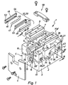
- Fluid operated gripper has a housing 2 with a For example, cuboid middle part 3, at the two axial end faces end cover 4, 4 'are attached.
- the middle part 3 forms a main body 5 of a general denoted by reference numeral 6 linear guide, the principalsbeipiel also two as runners 7, 7 'designated Contains components that of the gripper element holders 8, 8 'of the Gripper 1 are formed.
- About guide means 12 are the Runners 7, 7 'on the base body 5 in the direction of its longitudinal axis 13 slidably guided and simultaneously in the transverse direction supported.
- the gripper element carrier 8, 8 ' are in the longitudinal direction of the housing 2 consecutively arranged and stand each with a housed in the housing 2 and indicated only schematically fluid actuated drive device 14 in drive connection.
- the structure of the drive device 14 may, for example the same as in US 5,657,973 is explained. It can be two with each one of the Gripping element carrier 8, 8 'movement-coupled driver 15th containing the fluid force induced axial movement two pistons of the drive device 14 on the gripper element carrier 8, 8 'transmitted. It is in particular a mode of operation possible, in which the gripper element carrier 8, 8 'a axially opposing linear movement relative to the housing.
- Gripping elements in the context of an opening or closing movement from each other or to approach each other.
- the Gripping elements which are also referred to as gripping jaws could, can be replaced via fasteners 16 to the gripping element carriers 8, 8 'fasten.
- the base body 5 formed by the central part 3 has a section referred to below as the base 17 in which housed in the embodiment, the drive device 14 is and essentially a plate or block-like Has shape.
- the two in the embodiment of the gripper element carriers 8, 8 'formed runners 7, 7' - instead of the gripper element carrier 8, 8 'could also be provided directly gripping elements be - engage in the groove-like depression 22, where they in the embodiment with a major part of her Cross-section engaging foot portion 23 in the groove-like Well 22 are included and the rest, with a Head portion 24, over the longitudinal opening 25 of the groove-like Protrude recess 22 and over the outer surface of the Projecting body 5.
- the above-mentioned guide means 12 are located inside the groove-like depression 22 and work there on both sides of a respective rotor 7, 7 'between this and the respective adjacent legs 18, 18 '.
- the one respective rotor 7, 7 'assigned Guide means 12 of two on both sides of the rotor 7, 7 ' arranged guide units 29 are made, which expediently have a later explained advantageous structure.
- the linear guide 6 also has between the two legs 18, 18 'acting clamping means 26, located in a way that an elastic deformation the legs 18, 18 'takes place relative to the base 17, wherein the width of the groove-like depression 22 changed.
- the deformation regions 28, 28 ' are expediently located in the transitional areas between the base 17 and the respective leg 18, 18 ', so that the deformation process can also be referred to as a bending process.
- the adjustment measures are designed especially for this reason particularly simple, because the legs 18, 18 'integral with the base 17 are connected and thus at a removal the clamping force automatically increasing the width of the groove-like depression 22 in the direction of its tension-free Starting position are deformed back.
- the clamping means 26 are of several rod-like clamping elements 27 formed in the two Legs 18, 18 'are anchored and the groove-like depression 22 in particular in the vicinity of the base 17 web-like traverse.
- the clamping elements 27 have the effect of tie rods and can be done in the tension sense of actuation cause the legs 18, 18 'to face each other be slightly bent elastically.
- the clamping elements 27 are clamping screws, wherein according to Figures 2 and 3 may be provided that they rest with their head 32 on one leg 18 ', while she's with her threaded shaft 33 in the other Legs are screwed.
- the clamping elements 27 extend in each case in two the legs 18, 18 'passing through and in the region of the groove-like depression 22 with each other aligned holes.
- the installation depth of the rotor 7, 7 'with respect the groove-like recess 22 is chosen so that they can run over the clamping elements 27.
- clamping elements 27 As is apparent from Figures 1 and 2, come expediently simultaneously several clamping elements 27 are used, the distributed over the length of the groove-like recess 22 at a distance are arranged and operate independently to let.
- the number of clamping elements 27 and their distribution density hangs over the length of the main body 5 away in particular of the length of the body 5 and the Guide route from.
- the Main body 5 in particular in the region of the two legs 18, 18 'provided with grooves that influence the deformation behavior, and the following in their entirety as Verformungsnuten 34 are designated.
- both legs 18, 18 'further deformation grooves 34 provided as a transverse grooves 38 are executed and which comparable to the outer Longitudinal grooves 36 in the lateral outer surfaces 35, 35 'of the Base body 5 are introduced.
- Their longitudinal course is, however in particular at right angles to that of the longitudinal grooves Directed 36, wherein they are parallel in the embodiment to the depth direction 42 of the groove-like recess 22 extend.
- the transverse grooves 38 extend only in the legs 18, 18 ', where they over as shown the entire height of the respective associated leg 18, 18 ' extend so that they one end facing away from the base 17 free end of a respective leg 18, 18 'and the other to that on the same lateral outer surface 35, 35 'provided longitudinal groove 36 are open.
- each leg 18, 18 ' has two such Transverse grooves 38.
- a respective leg 18, 18 'can deformation sections 43 form, to each of which a clamping means 26 or Clamping element 27 engages to one of the other deformation sections 43 essentially unaffected, localized Deformation of the respective leg 18, 18 make ' to be able to.
- a corresponding embodiment is the Embodiment before.
- FIG. 4 makes another advantageous use the transverse grooves 38 clearly.
- the longitudinal groove 36 associated with the front side Mouths of a respective pair of a transverse groove 38 and a Mounting hole 44 are thus aligned coaxially.
- a screw in the mounting hole 44 introduce at the same time a possibly existing head of the fastener in the lateral Outer surface 35, 35 'of the main body 5 sunk to lie comes.
- the guide units 29 could be made directly adjacent to each other abutting sliding surfaces consist of facing each other Side surfaces of the rotor 7, 7 'and the legs 18, 18 'are formed. Also, it would be conceivable to face each other Insert side surfaces groove-like depressions, in which held by cages rolling elements run, wherein they directly on the surfaces of the legs 18, 18 'and the Roll runners 7, 7 '. In the embodiment, another, realized as particularly advantageous design realized which makes it possible for the main body 5 a less To use wear-resistant material such as aluminum by the rolling surfaces 46 for a rolling element 47 at a separate Bearing elements 48 are provided.
- FIG. 1 and 4 contains a respective guide unit 29 a in the interior of the groove-like Recess 22 provided on the main body 5 first support body 52 and one opposite in the area of the facing side surface of the rotor 7, 7 'arranged second support body 53.
- the support bodies 52, 53 are expediently in longitudinal grooves the legs 18, 18 'and runners 7, 7' used to a to get compact width. They insist as well suitably made of plastic material.
- each support body 52, 53 are two longitudinal and each other provided parallel pockets, which have a slot-like Pass opening 55 in a longitudinal groove 57, which adjoin the front of the respective other support body facing of the respective supporting body is located.
- the opposing longitudinal grooves 56 of two associated define first and second support body 52, 53 a channel in which in the embodiment of rolling balls having Wälz redesignan ever 47 is housed.
- the Bearing elements 48 are rod-shaped and back the support body 52, 53 inserted into the pockets 54 and protrude with a section of its circumference through the slit-like Opening 55 in the associated longitudinal groove 56, wherein this Peripheral sections form the rolling surfaces 46, where the Rolling element 47 expires.
- the support Bearing elements 48 directly on the associated main body. 5 Runners 7,7 'from, so that the support body 52, 53 preferably are not in direct contact with these components and not be loaded in the transverse direction. They are expediently used only to receive the bearing elements 48 and to prevent their displacement in the longitudinal direction as well to exert an axial stop function with respect to the rolling elements.
- the bearing elements 48 are suitably made of hardened Steel and are very wear-resistant in this way. Furthermore
- the guide units can be mounted very easily. You can, for example, by a snap connection or through any other connection on the associated component be attached.
- a cover is still indicated, which in the embodiment the transition region between the two gripping element carriers 8, 8 'covered, in particular to penetrate to prevent contamination.
Description
Die Erfindung betrifft eine Linearführung, mit einem Grundkörper, der eine Basis und zwei unter seitlicher Begrenzung einer nutartigen Vertiefung von der Basis wegragende Schenkel aufweist, mit mindestens einem in die nutartige Vertiefung eingreifenden, relativ zum Grundkörper in Längsrichtung der nutartigen Vertiefung bewegbaren Läufer, und mit im Innern der nutartigen Vertiefung zwischen dem Läufer und den diesen flankierenden Schenkeln wirkenden Führungsmitteln, wobei zwischen den beiden Schenkeln des Grundkörpers wirkende Spannmittel vorhanden sind, die ein elastisches Verformen der Schenkel mit Bezug zur Basis ermöglichen, um im Bereich der Führungsmittel eine variable Einstellung der Breite der nutartigen Vertiefung vornehmen zu können.The invention relates to a linear guide, with a base body, one base and two below the side a groove-like depression of the base projecting leg having at least one in the groove-like depression engaging, relative to the main body in the longitudinal direction of groove-like recess movable runners, and with inside the groove-like depression between the runner and this flanking legs acting guide means, wherein between the two legs of the body acting clamping means are present, which is an elastic deformation of the Legs with respect to the base allow in the area of Guide means a variable adjustment of the width of the groove-like To be able to do well.
Bei einer aus der US-A-5460452 bekannten Linearführung dieser Art greift eine Führungsschiene zwischen zwei Schenkel einer Schlitteneinheit ein, wobei zwischen diesen Komponenten Wälzlagermittel vorgesehen sind. Zwischen den beiden Schenkeln erstreckt sich eine Regulierschraube, durch die sich der Abstand zwischen den beiden Schenkein einstellen lässt.In one known from US-A-5460452 linear guide this Art engages a guide rail between two legs of a Slide unit, wherein between these components rolling bearing means are provided. Between the two thighs extends a regulating screw, through which the distance between the two tavern.
Eine aus der US-A-5657973 hervorgehende Linearführung ist Bestanzteil eines fluidbetätigten Greifers. Das Gehäuse des Greifers, das eine durch Fluidkraft betätigte Antriebseinrichtung enthält, bildet einen Grundkörper mit zwei parallel zueinander angeordneten Schenkeln, die eine im Querschnitt beispielsweise T-förmige nutartige Vertiefung begrenzen. Darin sind zwei als Läufer bezeichenbare Greifelementträger linear verschiebbar geführt, die durch die Antriebseinrichtung zu einer gegensinnigen Linearbewegung veranlasst werden können, um mittels daran festgelegter Greifelemente Handhabungsarbeiten durchzuführen.A resulting from US-A-5657973 linear guide is Bestanzteil a fluid-operated gripper. The case of the Gripper, which is a driven by fluid power drive means contains, forms a basic body with two parallel arranged thighs, one in cross-section For example, limit T-shaped groove-like depression. In this are two markable as runners gripping element carrier linear slidably guided by the drive means can be caused to an opposing linear motion, handling work by means of gripping elements fixed thereto perform.
Um einen Greifer mit hoher Betriebspräzision zu erhalten, bedarf es einer exakten Abstimmung des Führungskontaktes zwischen den Läufern und dem Grundkörper. Im Falle der US-A-5675973 sind hierzu die Läufer durch entsprechend aufwendige mechanische Bearbeitung so exakt in die nutartige Vertiefung einzupassen, dass die einander zugewandten, Führungsmittel bildenden Seitenflächen in einer Weise aneinander anliegen, die möglichst spielfreie Linearbewegungen ohne Verklemmungsgefahr gewährleistet. Diese Anpassung hat eine kostenintensive Fertigung des Produkts zur Folge und wird gleichwohl immer ein Kompromiss sein, insbesondere wenn große Stückzahlen zu fertigen sind.In order to obtain a gripper with high operational precision, requires it of an exact coordination of the management contact between the runners and the body. In the case of US-A-5675973 For this purpose, the runners by correspondingly expensive mechanical processing so exactly in the groove-like depression to fit that facing each other, guiding means forming side surfaces in a manner abutting one another, the backlash-free linear movements without jamming danger guaranteed. This adjustment has a costly Production of the product results and will always be be a compromise, especially if large quantities too finished are.
Es ist die Aufgabe der vorliegenden Erfindung, eine sich insbesondere für fluidbetätigte Greifer eignende Linearführung zu schaffen, die bei relativ einfacher Herstellung eine hohe Führungspräzision zur Verfügung stellen kann.It is the object of the present invention, in particular suitable for fluid-operated gripper linear guide to create a relatively simple production with a high Can provide leadership precision.
Zur Lösung dieser Aufgabe ist vorgesehen, dass im Bereich eines oder beider Schenkel an der der nutartigen Vertiefung entgegengesetzten Außenfläche des Grundkörpers eine sich parallel zur Längsachse der nutartigen Vertiefung erstreckende Längsnut vorgesehen ist, wobei die Spannmittel auf der der Basis entgegengesetzten Seite der Längsnut am betreffenden Schenkel angreifen derart, daß die Längsnut zwishen den Spannmitteln und der Basis angeordnet ist. Auf diese Weise lässt sich das im Bereich der Führungsmittel gewünschte Führungsspiel zwischen den relativ zu bewegten Teilen der Linearführung sehr exakt und individuell einstellen. Durch die Spannmittel läßt sich die Breite der nutartigen Vertiefung im Bereich der Führungsmittel variieren, wobei die zu überwindende Rückstellkraft der beaufschlagten Schenkel eine sehr exakte und feinfühlige Justierung erlaubt. Da nun bei der Fertigung der einzelnen Komponenten mit größeren Toleranzen gearbeitet werden kann, die sich durch die nachfolgende Einstellung kompensieren lassen, ergibt sich eine vereinfachte Herstellung verbunden mit einer bei Bedarf hohen Führungspräzision. Die Linearführung eignet sich insbesondere zum Einsatz bei fluidbetätigten Greifern zur Führung der die Läufer bildenden Greifelemente oder Greifelementträger gegenüber dem Gehäuse des Greifers, ist aber auch ohne weiteres im Zusammenhang mit anderen Produkten einsetzbar, die mit einer Linearführung ausgestattet sind.To solve this problem is provided that in the field of or both legs at the groove-like depression opposite outer surface of the body a parallel extending to the longitudinal axis of the groove-like depression Longitudinal groove is provided, wherein the clamping means on the of Base opposite side of the longitudinal groove on the relevant Legs attack so that the longitudinal groove between the Clamping means and the base is arranged. In this way, this can be done in the area of the guide means desired leadership game between the relative to moving Parts of the linear guide set very accurately and individually. By the clamping means can be the width of the groove-like Deepening in the area of the guide vary, with to be overcome restoring force of the acted legs a very precise and sensitive adjustment allowed. There now in the production of individual components with larger ones Tolerances can be worked through by the following Compensate setting, resulting in a simplified production combined with a high if necessary Guiding precision. The linear guide is particularly suitable for use with fluid operated grippers to guide the Runners forming gripping elements or gripping element carrier opposite the housing of the gripper, but is also in the readily Can be used in conjunction with other products that come with a Linear guide are equipped.
Um das Verformungsverhalten der Schenkel in einer gewünschten Weise zu beeinflussen, ist der Grundkörper im Bereich der Schenkel mit die Struktur des Grundkörpers lokal schwächenden Nuten versehen, die nachfolgend als Verformungsnuten bezeichnet seien. Somit lässt sich erreichen, dass die erforderlichen Einstellungen zielgerecht und dennoch mit relativ geringer Verstellkraft vorgenommen werden können. Erfindungsgemäß ist im Bereich eines und vorzugsweise beider Schenkel eine als Längsnut ausgeführte Verformungsnut vorgesehen, die sich parallel zur Längsachse der nutartigen Vertiefung erstreckt. Sie kann sich insbesondere im Übergangsbereich zwischen dem betreffenden Schenkel und der Basis des Grundkörpers befinden. Wird in diesem Fall über die Spannmittel eine Kraft aufgebracht, ergibt sich ein aufeinander zu gerichtetes Verbiegen der Schenkel über ihre gesamte Höhe, wobei sich der Biegebereich im Übergangsbereich zwischen den Schenkeln und der Basis befindet. Möglich wäre es aber auch, die Längsnut näher zum freien Ende des jeweiligen Schenkels hin vorzusehen, so dass der betreffende Schenkel selbst über einen bei Betätigung der Spannmittel unbeeinflusst bleibenden Fußabschnitt und einen verformbaren Abschnitt unterteilt wird. To the deformation behavior of the legs in a desired Way of influencing, is the basic body in the field of Thighs locally weakening with the structure of the main body Provided grooves, hereinafter referred to as deformation grooves are. Thus it can be achieved that the required Attitudes purposefully and nevertheless with relatively less Adjustment can be made. According to the invention is in the range of one and preferably both legs one provided as a longitudinal groove running deformation, which is extends parallel to the longitudinal axis of the groove-like depression. It can be particularly in the transition area between the respective leg and the base of the body are located. If a force is applied in this case via the clamping means, results in a mutually directed bending the thigh over its entire height, with the bending area in the transition area between the thighs and the Base is located. But it would also be possible, the longitudinal groove closer to provide towards the free end of the respective leg, so that the leg itself about one on actuation the clamping means unaffected remaining foot section and a deformable section is divided.
Vorteilhafte Weiterbildungen der Erfindung gehen aus den Unteransprüchen hervor.Advantageous developments of the invention will become apparent from the dependent claims out.
Die Spannmittel sind zweckmäßigerweise zumindest teilweise von Spannelementen gebildet, die in oder an den beiden Schenkeln verankert sind und die nutartige Vertiefungen stegartig durchqueren. Dabei handelt es sich zweckmäßigerweise um Spannschrauben, die sich mit ihrem Kopf am einen Schenkel abstützen können, während sie mit ihrem Gewindeschaft in den anderen Schenkel eingeschraubt sind.The clamping means are expediently at least partially formed by clamping elements in or on the two legs are anchored and the groove-like depressions web-like traverse. This is expediently around Clamping screws, which are supported with their head on one leg while they are with their threaded shank in the other legs are screwed.
In Abhängigkeit von der Baulänge der Linearführung können mehrere über die Länge der nutartigen Vertiefung verteilt angeordnete Spannmittel vorgesehen sein, die sich insbesondere unabhängig voneinander betätigen lassen.Depending on the length of the linear guide can a plurality of distributed over the length of the groove-like depression arranged Be provided clamping means, in particular can be operated independently.
Es ist weiterhin von Vorteil, wenn insbesondere bei Grundkörpern größerer Länge im Bereich der Schenkel mindestens eine als Quernut ausgeführte Verformungsnut vorgesehen ist, die sich parallel zur Tiefenrichtung der nutartigen Vertiefung erstreckt, so daß der betreffende Schenkel über seine Länge hinweg in mehrere Verformungsabschnitte unterteilt wird. Ist jedem Verformungsabschnitt ein eigenes Spannmittel zugeordnet, kann eine sehr individuelle und feinfühlige Einstellung des Führungsspiels vorgenommen werden, wobei sich die Einstellungen gegenseitig nicht oder zumindest nur geringfügig beeinflussen.It is furthermore advantageous, in particular in the case of basic bodies greater length in the region of the legs at least one designed as a transverse groove deformation groove is provided, the parallel to the depth direction of the groove-like depression extends so that the leg concerned over its length is divided into several deformation sections. is each deformation section assigned its own clamping device, can be a very individual and sensitive attitude of the guiding game, taking care of the settings not mutually or at least only slightly influence.
Als vorteilhaft wird es angesehen, wenn jedem Schenkel eine Anordnung von Verformungsnuten zugeordnet ist, bei der es sich um eine Kombination aus Längsnuten und Quernuten handelt, die auch ineinander übergehen können.It is considered advantageous if each leg one Assigned arrangement of deformation grooves in which it is a combination of longitudinal grooves and transverse grooves, which can also merge into each other.
Die Führungsmittel können beispielsweise so ausgeführt sein, daß sich eine Gleitführung ergibt, wobei die Führungsmittel von einander zugewandten und miteinander in Kontakt stehenden Seitenflächen des Läufers und der Schenkel gebildet sein können. Insbesondere wenn höhere Querbelastungen auftreten, bietet sich allerdings die Ausgestaltung als Wälzführung an. Hierbei kann die Linearführung vorzugsweise derart ausgeführt sein, daß die Führungsmittel auf jeder Seite des Läufers über mindestens eine Führungseinheit verfügen, die einen am Grundkörper festgelegten ersten Tragkörper und einen am Läufer festgelegten zweiten Tragkörper enthalten, wobei jeder Tragkörper wenigstens ein und zweckmäßigerweise zwei parallel nebeneinanderliegend angeordnete und jeweils eine Abwälzfläche definierende stabförmige Lagerelemente trägt, und wobei zwischen den Tragkörpern eine an den Lagerelementen anliegende Wälzkörperanordnung vorgesehen ist. Die Tragkörper bestehen hier zweckmäßigerweise aus Kunststoffmaterial, während man als Lagerelemente vorzugsweise Bauteile aus gehärtetem Stahl verwendet.The guide means may for example be designed so that results in a sliding guide, wherein the guide means facing each other and in contact with each other Side surfaces of the rotor and the legs may be formed. Especially when higher lateral loads occur, offers However, the design as Wälzführung. In this case, the linear guide may preferably be designed in this way be that the guide means on each side of the runner over have at least one leadership unit, the one on the main body fixed first support body and one on the runner fixed second support body, each supporting body at least one and expediently two parallel next to each other arranged and each a rolling surface carrying defining rod-shaped bearing elements, and wherein between the support bodies a fitting to the bearing elements Rolling element arrangement is provided. The support bodies exist here expediently of plastic material while you as bearing elements preferably components made of hardened steel used.
Nachfolgend wird die Erfindung anhand der beiliegenden Zeichnung
näher erläutert. In dieser zeigen:
Der in der Zeichnung allgemein mit Bezugsziffer 1 bezeichnete
fluidbetätigte Greifer verfügt über ein Gehäuse 2 mit einem
beispielsgemäß quaderähnlichen Mittelteil 3, an dessen beiden
axialen Stirnseiten Abschlußdeckel 4, 4' angesetzt sind.The generally designated by reference numeral 1 in the drawing
Fluid operated gripper has a
Das Mittelteil 3 bildet einen Grundkörper 5 einer allgemein
mit Bezugsziffer 6 bezeichneten Linearführung, die beim Ausführungsbeipiel
auch noch zwei als Läufer 7, 7' bezeichnete
Bauteile enthält, die von den Greifelementtägern 8, 8' des
Greifers 1 gebildet sind. Über Führungsmittel 12 sind die
Läufer 7, 7' an dem Grundkörper 5 in Richtung dessen Längsachse
13 verschiebbar geführt und gleichzeitig in Querrichtung
abgestützt.The
Die Greifelementträger 8, 8' sind in Längsrichtung des Gehäuses
2 aufeinanderfolgend angeordnet und stehen jeweils mit
einer im Gehäuse 2 untergebrachten und nur schematisch angedeuteten
fluidbetätigten Antriebseinrichtung 14 in Antriebsverbindung.
Der Aufbau der Antriebseinrichtung 14 kann beispielsweise
demjenigen entsprechen wie er in der US 5,657,973
erläutert wird. Dabei kann sie zwei mit jeweils einem der
Greifelementträger 8, 8' bewegungsgekoppelte Mitnehmer 15
enthalten, die die durch Fluidkraft hervorgerufene Axialbewegung
zweier Kolben der Antriebseinrichtung 14 auf die Greifelementträger
8, 8' übertragen. Es ist insbesondere eine Betriebsweise
möglich, bei der die Greifelementträger 8, 8' eine
axial gegensinnige Linearbewegung relativ zum Gehäuse 2
ausführen, um an ihnen vorgesehene, nicht näher dargestellte
Greifelemente im Rahmen einer Öffnungs- oder Schließbewegung
voneinander zu entfernen oder aneinander anzunähern. Die
Greifelemente, die auch als Greifbacken bezeichnet werden
könnten, lassen sich über Befestigungsmittel 16 auswechselbar
an den Greifelementträgern 8, 8' befestigen.The
Der von dem Mittelteil 3 gebildete Grundkörper 5 verfügt über
einen nachfolgend als Basis 17 bezeichneten Abschnitt, in dem
beim Ausführungsbeispiel die Antriebseinrichtung 14 untergebracht
ist und die im wesentlichen eine platten- oder klotzähnliche
Form hat. The
An die Basis 17 schließen sich längsseits zwei als Schenkel
18, 18' bezeichnete Grundkörperabschnitte an, die in Längsrichtung
des Grundkörpers 5 verlaufen und in Querrichtung von
der Basis 17 wegragen, so daß der Grundkörper 5 im Querschnitt
gesehen eine insgesamt U-ähnliche Gestalt hat. Die
Schenkel 18, 18' verlaufen parallel zueinander und liegen
sich mit Abstand gegenüber, wobei sie die seitlichen Begrenzungswände
einer zwischen ihnen angeordneten nutartigen Vertiefung
22 bilden. Den Grund dieser nutartigen Vertiefung 22
bildet der die beiden Schenkel 18, 18' miteinander verbindende
Abschnitt der Basis 17.Two close to the
Die beiden beim Ausführungsbeispiel von den Greifelementträgern
8, 8' gebildeten Läufer 7, 7' - anstelle der Greifelementträger
8, 8' könnten auch direkt Greifelemente vorgesehen
sein - greifen in die nutartige Vertiefung 22 ein, wobei sie
beim Ausführungsbeispiel mit einem den größten Teil ihres
Querschnitts einnehmenden Fußabschnitt 23 in der nutartigen
Vertiefung 22 aufgenommen sind und im übrigen, mit einem
Kopfabschnitt 24, über die längsseitige Öffnung 25 der nutartigen
Vertiefung 22 hinausragen und über die Außenfläche des
Grundkörpers 5 vorstehen.The two in the embodiment of the
Die oben erwähnten Führungsmittel 12 befinden sich im Innern
der nutartigen Vertiefung 22 und arbeiten dort beidseits eines
jeweiligen Läufers 7, 7' zwischen diesem und dem jeweils
benachbarten Schenkel 18, 18'. Beim Ausführungsbeispiel ist
vorgesehen, daß die einem jeweiligen Läufer 7, 7' zugeordneten
Führungsmittel 12 aus zwei beidseits des Läufers 7, 7'
angeordneten Führungseinheiten 29 bestehen, die zweckmäßigerweise
einen später noch erläuterten vorteilhaften Aufbau besitzen.The above-mentioned guide means 12 are located inside
the groove-
Die Linearführung 6 verfügt desweiteren über zwischen den
beiden Schenkeln 18, 18' wirkende Spannmittel 26, die sich in
einer Weise betätigen lassen, daß eine elastische Verformung
der Schenkel 18, 18' relativ zur Basis 17 erfolgt, wobei sich
die Breite der nutartigen Vertiefung 22 verändert. Die Schenkel
18, 18' werden dabei in Querrichtung der nutartigen Vertiefung
22 entweder einander angenähert oder voneinander entfernt.
Die Verformungsbereiche 28, 28' liegen dabei zweckmäßigerweise
in den Übergangsbereichen zwischen der Basis 17
und dem jeweiligen Schenkel 18, 18', so daß man den Verformungsvorgang
auch als Biegevorgang bezeichnen kann.The linear guide 6 also has between the
two
Durch die Einstellung der Breite der nutartigen Vertiefung 22
wird Einfluß genommen auf das Führungsspiel im Bereich der
Führungsmittel 12 zwischen den Schenkeln 18, 18' und den Läufern
7, 7'. Man kann auf diese Weise insbesondere eine Einstellung
derart vornehmen, daß die Läufer 7, 7' zumindest
weitestgehend spielfrei und dennoch in Längsrichtung der nutartigen
Vertiefung 22 verschieblich am Grundkörper 5 geführt
sind.By adjusting the width of the groove-like depression 22nd
is influenced on the leadership game in the area of
Guide means 12 between the
Die Einstellmaßnahmen gestalten sich vor allem auch deshalb
besonders einfach, weil die Schenkel 18, 18' einstückig mit
der Basis 17 verbunden sind und sie somit bei einer Wegnahme
der Spannkraft selbsttätig unter Vergrößerung der Breite der
nutartigen Vertiefung 22 in Richtung ihrer spannungsfreien
Ausgangsstellung zurückverformt werden. The adjustment measures are designed especially for this reason
particularly simple, because the
Beim Ausführungsbeispiel sind die Spannmittel 26 von mehreren
stabähnlichen Spannelementen 27 gebildet, die in den beiden
Schenkeln 18, 18' verankert sind und die nutartige Vertiefung
22 insbesondere in der Nachbarschaft der Basis 17 stegartig
durchqueren. Die Spannelemente 27 haben die Wirkung von Zugankern
und können bei im Spannsinne erfolgender Betätigung
hervorrufen, daß die Schenkel 18, 18' aufeinander zu gerichtet
elastisch geringfügig gebogen werden.In the embodiment, the clamping means 26 are of several
rod-
Bevorzugt handelt es sich bei den Spannelementen 27 um Spannschrauben,
wobei gemäß Figuren 2 und 3 vorgesehen sein kann,
daß sie sich mit ihrem Kopf 32 am einen Schenkel 18' abstützen,
während sie mit ihrem Gewindeschaft 33 in den anderen
Schenkel eingeschraubt sind. Die Spannelemente 27 erstrecken
sich dabei jeweils in zwei die Schenkel 18, 18' durchsetzenden
und im Bereich der nutartigen Vertiefung 22 miteinander
fluchtenden Bohrungen. Die Einbautiefe der Läufer 7, 7' bezüglich
der nutartigen Vertiefung 22 ist so gewählt, daß sie
über den Spannelementen 27 hinweglaufen können.Preferably, the clamping
Wie aus Figuren 1 und 2 ersichtlich ist, kommen zweckmäßigerweise
gleichzeitig mehrere Spannelemente 27 zum Einsatz, die
über die Länge der nutartigen Vertiefung 22 mit Abstand verteilt
angeordnet sind und sich unabhängig voneinander betätigen
lassen. Die Anzahl der Spannelemente 27 und deren Verteilungsdichte
über die Länge des Grundkörpers 5 hinweg hängt
insbesondere von der Baulänge des Grundkörpers 5 bzw. der
Führungsstrecke ab. Jedenfalls besteht durch diese Mehrfachanordnung
von Spannelementen 27 der Vorteil, daß sich
über die Länge der nutartigen Vertiefung 22 hinweg auftretende
toleranzbedingte Breitendifferenzen bequem lokal kompensieren
lassen, wobei sich die vorgenommenen Einstellungen der
einzelnen Spannelemente nicht oder zumindest nur geringfügig
aufeinander auswirken.As is apparent from Figures 1 and 2, come expediently
simultaneously several clamping
Handelt es sich bei dem Grundkörper 5 um ein verhältnismäßig
dünnwandiges Bauteil, kann die dem Material inhärente Biegeelastizität
bereits ausreichend sein, um die gewünschten Verformungen
durchführen zu können. Bei größerer Wandstärke, wie
sie beim Ausführungsbeispiel auftritt, empfiehlt es sich, den
Grundkörper 5 insbesondere im Bereich der beiden Schenkel 18,
18' mit Nuten zu versehen, die das Verformungsverhalten beeinflussen,
und die nachfolgend in ihrer Gesamtheit als Verformungsnuten
34 bezeichnet seien.Is it in the
Beim Ausführungsbeispiel ist der Grundkörper 5 im Übergangsbereich
zwischen einem jeweiligen Schenkel 18, 18' und der
Basis 17 an seinen der nutartigen Vertiefung 22 in Querrichtung
entgegengesetzten seitlichen Außenflächen 35, 35' mit
einer sich parallel zur nutartigen Vertiefung 22 erstreckenden
Längsnut 36 als Verformungsnut 34 versehen. Sie erstreckt
sich zweckmäßigerweise über die gesamte Länge des Grundkörpers
5 und ist vergleichbar einem Einschnitt in den Grundkörper
5 eingebracht.In the embodiment of the
Desweiteren können ausgehend vom Innern der nutartigen Vertiefung
22 weitere Längsnuten 37 in den Grundkörper 5 eingebracht
sein, die sich parallel zu den äußeren Längsnuten 36
erstrecken und deren Tiefenrichtung so orientiert ist, daß
sie zum Nutgrund der äußeren Längsnuten 36 ragen. Der zwischen
den Nutgründen der einander zugeordneten inneren und
äußeren Längsnuten 36, 37 verbleibende Materialbereich des
Grundkörpers 5 bildet hierbei die Verformungsbereiche 28,
28'.Furthermore, starting from the inside of the groove-
Zweckmäßigerweise sind zusätzlich im Bereich beider Schenkel
18, 18' weitere Verformungsnuten 34 vorgesehen, die als Quernuten
38 ausgeführt sind und welche vergleichbar den äußeren
Längsnuten 36 in die seitlichen Außenflächen 35, 35' des
Grundkörpers 5 eingebracht sind. Ihr Längsverlauf ist allerdings
insbesondere rechtwinkelig zu demjenigen der Längsnuten
36 gerichtet, wobei sie sich beim Ausführungsbeispiel parallel
zur Tiefenrichtung 42 der nutartigen Vertiefung 22 erstrecken.
Vorzugsweise verlaufen die Quernuten 38 lediglich
in den Schenkeln 18, 18', wobei sie sich wie abgebildet über
die gesamte Höhe des jeweils zugeordneten Schenkels 18, 18'
erstrecken, so daß sie einenends zu dem der Basis 17 abgewandten
freien Ende eines jeweiligen Schenkels 18, 18' und
andernendes zu der an der gleichen seitlichen Außenfläche 35,
35' vorgesehenen Längsnut 36 offen sind.Conveniently, in addition, in the region of both
Die Anzahl der einer jeweiligen seitlichen Außenfläche 35,
35' zugeordneten Quernuten 38 und deren in Längsrichtung der
nutartigen Vertiefung 22 gemessener Abstand zueinander wird
zweckmäßigerweise in Abhängigkeit von der Baulänge der zu
verformenden Schenkel 18, 18' gewählt. Beim Ausführungsbespiel
verfügt jeder Schenkel 18, 18' über zwei derartige
Quernuten 38. The number of a respective lateral
Die durch die Quernuten 38 voneinander abgeteilten Bereiche
eines jeweiligen Schenkels 18, 18' können Verformungsabschnitte
43 bilden, an denen jeweils ein Spannmittel 26 oder
Spannelement 27 angreift, um eine von den übrigen Verformungsabschnitten
43 im wesentlichen unbeeinflußte, lokal begrenzte
Verformung des betreffenden Schenkels 18, 18' vornehmen
zu können. Eine entsprechende Ausgestaltung liegt beim
Ausführungsbeispiel vor.The separated by the
Die Figur 4 macht einen weiteren vorteilhaften Verwendungszweck
der Quernuten 38 deutlich. Hier ist die Basis 17 in linearer
Verlängerung einer jeweiligen Quernut 38 von einer Befestigungsbohrung
44 durchsetzt, die zum einen auf der der
längsseitigen Öffnung 25 entgegengesetzten und beim Ausführungsbeispiel
unteren Außenfläche 45 des Grundkörpers 5 ausmündet
und zum andern zur zugeordneten äußeren Längsnut 36
hin offen ist. Die der Längsnut 36 zugeordneten stirnseitigen
Mündungen eines jeweiligen Paares einer Quernut 38 und einer
Befestigungsbohrung 44 fluchten also koaxial. Somit ist es
möglich, über eine jeweilige Quernut 38 hinweg ein Befestigungselement,
beispielsweise eine Schraube, in die Befestigungsbohrung
44 einzuführen, wobei gleichzeitig ein eventuell
vorhandener Kopf des Befestigungselementes in der seitlichen
Außenfläche 35, 35' des Grundkörpers 5 versenkt zu liegen
kommt.FIG. 4 makes another advantageous use
the
Die Führungseinheiten 29 könnten aus unmittelbar aneinander
anliegenden Gleitflächen bestehen, die von den einander zugewandten
Seitenflächen der Läufer 7, 7' und der Schenkel 18,
18' gebildet sind. Auch wäre es denkbar, in die einander zugewandten
Seitenflächen nutartige Vertiefungen einzubringen,
in denen durch Käfige gehaltene Wälzelemente laufen, wobei
sie unmittelbar an den Flächen der Schenkel 18, 18' und der
Läufer 7, 7' abrollen. Beim Ausführungsbeispiel ist eine weitere,
als besonders vorteilhaft erachtete Bauform verwirklicht,
die es ermöglicht, für den Grundkörper 5 ein weniger
verschleißfestes Material wie Aluminium zu verwenden, indem
die Abwälzflächen 46 für eine Wälzkörperanordnung 47 an separaten
Lagerelementen 48 vorgesehen sind.The
Wie insbesondere aus Figuren 1 und 4 hervorgeht, enthält eine
jeweilige Führungseinheit 29 einen im Innern der nutartigen
Vertiefung 22 am Grundkörper 5 vorgesehenen ersten Tragkörper
52 und einen gegenüberliegend im Bereich der zugewandten Seitenfläche
des Läufers 7, 7' angeordneten zweiten Tragkörper
53. Die Tragkörper 52, 53 sind zweckmäßigerweise in Längsnuten
der Schenkel 18, 18' bzw. Läufer 7, 7' eingesetzt, um eine
kompakte Baubreite zu erhalten. Sie bestehen außerdem
zweckmäßigerweise aus Kunststoffmaterial.As is apparent in particular from Figures 1 and 4, contains a
respective guide unit 29 a in the interior of the groove-
An jedem Tragkörper 52, 53 sind zwei längsverlaufende und zueinander
parallele Taschen vorgesehen, die über eine schlitzartige
Öffnung 55 in eine Längsnut 57 übergehen, die sich an
der dem jeweils anderen Tragkörper zugewandten Vorderseite
des jeweiligen Tragkörpers befindet.At each
Die sich gegenüberliegenden Längsnuten 56 zweier einander zugeordneter
erster und zweiter Tragkörper 52, 53 definieren
einen Kanal, in dem die beim Ausführungsbeispiel über Wälzkugeln
verfügende Wälzkörperanordnung 47 untergebracht ist. Die
Lagerelemente 48 sind stabförmig ausgeführt und rückseitig
der Tragkörper 52, 53 in die Taschen 54 eingelegt und ragen
mit einem Abschnitt ihres Umfanges durch die schlitzartige
Öffnung 55 in die zugeordnete Längsnut 56 hinein, wobei diese
Umfangsabschnitte die Abwälzflächen 46 bilden, an denen die
Wälzkörperanordnung 47 abläuft. Andererseits stützen sich die
Lagerelemente 48 unmittelbar am zugeordneten Grundkörper 5
bzw. Läufer 7,7' ab, so daß die Tragkörper 52, 53 vorzugsweise
nicht in direktem Kontakt mit diesen Bauteilen stehen und
nicht in Querrichtung belastet werden. Sie dienen zweckmäßigerweise
lediglich dazu, die Lagerelemente 48 aufzunehmen und
deren Verschiebbarkeit in Längsrichtung zu verhindern sowie
eine axiale Anschlagfunktion bezüglich der Wälzkörper auszuüben.The opposing
Die Lagerelemente 48 bestehen zweckmäßigerweise aus gehärtetem
Stahl und sind auf diese Weise sehr verschleißfest. Außerdem
lassen sich die Führungseinheiten sehr einfach montieren.
Sie können beispielsweise durch eine Rastverbindung oder
durch jede beliebige andere Verbindung am zugeordneten Bauteil
befestigt werden.The bearing
Bei 58 ist noch eine Abdeckung angedeutet, die beim Ausführungsbeispiel
den Übergangsbereich zwischen den beiden Greifelementträgern
8, 8' überdeckt, um insbesondere ein Eindringen
von Verunreinigungen zu verhindern.At 58, a cover is still indicated, which in the embodiment
the transition region between the two gripping
Claims (16)
- Linear guide with a main body unit (5) which has a base (17) and, projecting from the base, two arms (18, 181) the sides of which end in a groove-like hollow section (22), with at least one slide (7, 71) meshing with the groove-like hollow section (22) and movable relative to the main body unit (5) along the length of the groove-like hollow section (22) and with, on the inside of the groove-like hollow section (22), guide means (12) acting between the slide (7, 71) and the arms (18, 181) running alongside it, whereby tensioning means (26) are available, acting between the two arms (18, 181), which enable an elastic reshaping of the arms (18, 181) to be made with reference to the base (17), so as to allow a variable setting to be made of the width of the groove-like hollow section (22) in the area of the guide means (12), characterized in that, in the area of one or both arms on the outer surface (35, 351) of the main body unit (5) opposite the groove-like hollow section (22), a longitudinal groove (36) is provided extending parallel to the longitudinal axis of the groove-like hollow section (22), whereby the tensioning means (26) to the side of the longitudinal groove (36) opposite the base (17) make contact with the arm (18, 181) in question, in such a way that the longitudinal groove (36) is positioned between the tensioning means (26) and the base (17).
- Linear guide according to claim 1, characterized in that the arms (18, 181) form one piece with the base (17).
- Linear guide according to claim 1 or 2, characterized in that the tensioning means (26) are formed at least partly from tensioning elements (27) fixed in or to both arms (18, 181) and crossing the groove-like hollow section (22) in the manner of a bridge.
- Linear guide according to claim 3, characterized in that the tensioning elements (27) are formed from tensioning screws.
- Linear guide according to one of claims 1 to 4, characterized in that, distributed along the length of the groove-like hollow section (22), several tensioning means (26) are provided, positioned at a distance from each other, which, in particular, can be operated independently of one another.
- Linear guide according to one of claims 1 to 5, characterized in that the longitudinal groove (36) is in the area where the arm (18, 181) in question and the base (17) meet.
- Linear guide according to one of claims 1 to 6, characterized in that, in the area of one or several arms (18, 181), at least one transverse groove (38) is provided on the outer surface (35, 351) of the main body unit (5) opposite the groove-like hollow section (22), extending parallel to the downward orientation (42) of the groove-like hollow section (22).
- Linear guide according to claim 7, characterized in that the arm (18, 181) in question has several transverse grooves (38) positioned along it at a distance from each other.
- Linear guide according to claim 7 or 8, characterized in that the arm in question is subdivided by at least one transverse groove into several shaped segments (43), with each of which at least one tensioning means (26) makes contact.
- Linear guide according to one of claims 7 to 9, characterized in that the transverse grooves (38) each join up with a longitudinal groove (36).
- Linear guide according to one of claims 7 to 10, characterized in that the transverse grooves (38) extend to the entire height of the arm (18, 181) to which each of them relates.
- Linear guide according to one of claims 7 to 11, characterized in that at least one transverse groove (38) is open towards the free end of the arm (18, 181) to which it belongs, whereby the opposite end of this transverse groove (38), facing the base (17), lies opposite the opening of a fastening bore, passing through the base (17).
- Linear guide according to one of claims 1 to 12, characterized in that the guide means (12) on each side of the slide (7, 71) are equipped with at least one guide unit (29) which contains a first carrying component (52) relating to the main body unit (5) and a second carrying component (53) relating to the slide (7, 71), whereby each carrying component (52, 53) carries at least one rod-shaped bearing element (48) constituting a rolling surface (46) and whereby, between the carrying components (52, 53) of one particular guide unit (29) a set of rolling components (47) is provided adjacent to the bearing elements (48).
- Linear guide according to claim 13, characterized in that, on each carrying component (52, 53), two bearing elements (48) parallel to each other are provided, at the same time being adjacent to the set of rolling components (47).
- Linear guide according to claim 13 or 14, characterized in that the carrying components (52, 53) are made of synthetic material, whereas the bearing elements, according to function, are made of tempered steel.
- Linear guide according to one of claims 1 to 15, characterized in that the main body unit (5) is a component of the casing (2) of a fluid-activated gripper (1), whereby at least one slide (7, 71) takes the form of a gripping element or a gripping element carrier (8, 81) of the gripper (1).
Applications Claiming Priority (2)
| Application Number | Priority Date | Filing Date | Title |
|---|---|---|---|
| DE29819265U DE29819265U1 (en) | 1998-10-29 | 1998-10-29 | Linear guide |
| DE29819265U | 1998-10-29 |
Publications (2)
| Publication Number | Publication Date |
|---|---|
| EP0997655A1 EP0997655A1 (en) | 2000-05-03 |
| EP0997655B1 true EP0997655B1 (en) | 2005-02-23 |
Family
ID=8064541
Family Applications (1)
| Application Number | Title | Priority Date | Filing Date |
|---|---|---|---|
| EP99119655A Expired - Lifetime EP0997655B1 (en) | 1998-10-29 | 1999-10-04 | Linear guide |
Country Status (2)
| Country | Link |
|---|---|
| EP (1) | EP0997655B1 (en) |
| DE (2) | DE29819265U1 (en) |
Cited By (1)
| Publication number | Priority date | Publication date | Assignee | Title |
|---|---|---|---|---|
| DE202010009782U1 (en) | 2010-07-02 | 2010-09-09 | Festo Ag & Co. Kg | hook assembly |
Families Citing this family (7)
| Publication number | Priority date | Publication date | Assignee | Title |
|---|---|---|---|---|
| DE19931133A1 (en) * | 1999-07-06 | 2001-01-25 | Festo Ag & Co | Method for producing linear guide comprising movable component gripped between arms of stationary component comprises fastening together two base components each of which carries one arm, to form stationary component |
| DE102006007068A1 (en) | 2006-02-15 | 2007-08-16 | Robert Bosch Gmbh | Linear guide device with Vorspannungseinstelleinrichtung |
| DE102007016436A1 (en) | 2007-04-05 | 2008-10-09 | Festo Ag & Co. Kg | Electrically actuatable gripping device, has electric drive arranged adjacent to spindle drive, where output shaft of electric drive and drive spindle of spindle drive are drivingly coupled with one another by coupling gear |
| DE102008019582A1 (en) * | 2008-04-18 | 2009-10-22 | Robert Bosch Gmbh | Linear movement device, has separate elongated clamp bolt whose material possesses thermal expansion coefficient which is less than that of in region of one of guiding parts, where region is adjacent to clamp bolt |
| DE102013019035B4 (en) * | 2013-11-15 | 2019-05-09 | Günther Zimmer | Gripping device with guide groove seal |
| DE102013019034B4 (en) * | 2013-11-15 | 2019-05-09 | Günther Zimmer | Gripping device with separate guide rails |
| DE102021203434B4 (en) | 2021-04-07 | 2023-02-09 | Festo Se & Co. Kg | linear motion device |
Family Cites Families (4)
| Publication number | Priority date | Publication date | Assignee | Title |
|---|---|---|---|---|
| JPS59222619A (en) * | 1983-05-30 | 1984-12-14 | Hiroshi Teramachi | Adjustment of gap of bearings for linear sliding |
| DE3931397A1 (en) * | 1989-09-20 | 1991-03-28 | Star Gmbh | ROLLER BEARING FOR LINEAR MOVEMENT KEYWORD: RAIL GUIDE WITH PRELOAD ADJUSTMENT |
| JP2582585Y2 (en) * | 1993-02-25 | 1998-10-08 | 日本トムソン株式会社 | Linear motion rolling guide unit |
| DE29518242U1 (en) * | 1995-11-17 | 1996-01-11 | Isel Automation Hugo Isert | Linear guide |
-
1998
- 1998-10-29 DE DE29819265U patent/DE29819265U1/en not_active Expired - Lifetime
-
1999
- 1999-10-04 EP EP99119655A patent/EP0997655B1/en not_active Expired - Lifetime
- 1999-10-04 DE DE59911652T patent/DE59911652D1/en not_active Expired - Lifetime
Cited By (1)
| Publication number | Priority date | Publication date | Assignee | Title |
|---|---|---|---|---|
| DE202010009782U1 (en) | 2010-07-02 | 2010-09-09 | Festo Ag & Co. Kg | hook assembly |
Also Published As
| Publication number | Publication date |
|---|---|
| DE29819265U1 (en) | 1999-01-28 |
| DE59911652D1 (en) | 2005-03-31 |
| EP0997655A1 (en) | 2000-05-03 |
Similar Documents
| Publication | Publication Date | Title |
|---|---|---|
| EP0868965B1 (en) | Carriage drive mechanisme | |
| EP1272409B1 (en) | Handling gear for repositioning pieces | |
| EP2977145B2 (en) | Centrical tensioning device | |
| WO1985005586A1 (en) | Protection installation for the guide track of two machine parts which are driven and supported in a longitudinal manner in relation to one another | |
| EP1197319B2 (en) | Wedge drive | |
| DE112007001185B4 (en) | Adjustable linear slide and assembly method | |
| DE102005006398A1 (en) | Device for gripping and holding a component | |
| DE3718157A1 (en) | VICE | |
| EP0997655B1 (en) | Linear guide | |
| DE19600314C2 (en) | Relay with positively driven contact sets | |
| DE102011054063B4 (en) | Drive device for a support member for supporting a workpiece | |
| EP1577053A1 (en) | Linear actuator with a slide guided on two side guides | |
| DE3151275C2 (en) | Fixing device for tools | |
| EP3563990B1 (en) | Gripping device with optimized double push wedge member ii | |
| DE3420857A1 (en) | Gripping apparatus with gripper jaw | |
| EP0410115B1 (en) | Chucking device | |
| EP1000684B1 (en) | Transport device for stepwise transport of workpieces in a production machine | |
| DE3113185C2 (en) | Stop system for the linear unit of a handling device | |
| EP1263546B1 (en) | Linear drive unit | |
| DE4208737B4 (en) | Rolling bearing longitudinal guide unit with extended mounting options | |
| EP0641940A2 (en) | Joint assembly for profiled elements | |
| DE3513214A1 (en) | WORK CYLINDERS WITH BALL GUIDE | |
| DE102006007771B4 (en) | Device with guide and removable waisted cam | |
| DE102005012297B4 (en) | forging machine | |
| DE3338898C2 (en) |
Legal Events
| Date | Code | Title | Description |
|---|---|---|---|
| PUAI | Public reference made under article 153(3) epc to a published international application that has entered the european phase |
Free format text: ORIGINAL CODE: 0009012 |
|
| AK | Designated contracting states |
Kind code of ref document: A1 Designated state(s): DE FR GB IT |
|
| AX | Request for extension of the european patent |
Free format text: AL;LT;LV;MK;RO;SI |
|
| 17P | Request for examination filed |
Effective date: 20000310 |
|
| AKX | Designation fees paid |
Free format text: DE FR GB IT |
|
| 17Q | First examination report despatched |
Effective date: 20031114 |
|
| GRAP | Despatch of communication of intention to grant a patent |
Free format text: ORIGINAL CODE: EPIDOSNIGR1 |
|
| GRAS | Grant fee paid |
Free format text: ORIGINAL CODE: EPIDOSNIGR3 |
|
| GRAA | (expected) grant |
Free format text: ORIGINAL CODE: 0009210 |
|
| AK | Designated contracting states |
Kind code of ref document: B1 Designated state(s): DE FR GB IT |
|
| REG | Reference to a national code |
Ref country code: GB Ref legal event code: FG4D Free format text: NOT ENGLISH |
|
| GBT | Gb: translation of ep patent filed (gb section 77(6)(a)/1977) |
Effective date: 20050223 |
|
| REF | Corresponds to: |
Ref document number: 59911652 Country of ref document: DE Date of ref document: 20050331 Kind code of ref document: P |
|
| PLBE | No opposition filed within time limit |
Free format text: ORIGINAL CODE: 0009261 |
|
| STAA | Information on the status of an ep patent application or granted ep patent |
Free format text: STATUS: NO OPPOSITION FILED WITHIN TIME LIMIT |
|
| 26N | No opposition filed |
Effective date: 20051124 |
|
| ET | Fr: translation filed | ||
| PGFP | Annual fee paid to national office [announced via postgrant information from national office to epo] |
Ref country code: GB Payment date: 20130815 Year of fee payment: 15 |
|
| PGFP | Annual fee paid to national office [announced via postgrant information from national office to epo] |
Ref country code: FR Payment date: 20131018 Year of fee payment: 15 |
|
| PGFP | Annual fee paid to national office [announced via postgrant information from national office to epo] |
Ref country code: IT Payment date: 20131004 Year of fee payment: 15 |
|
| GBPC | Gb: european patent ceased through non-payment of renewal fee |
Effective date: 20141004 |
|
| PG25 | Lapsed in a contracting state [announced via postgrant information from national office to epo] |
Ref country code: GB Free format text: LAPSE BECAUSE OF NON-PAYMENT OF DUE FEES Effective date: 20141004 |
|
| REG | Reference to a national code |
Ref country code: FR Ref legal event code: ST Effective date: 20150630 |
|
| PG25 | Lapsed in a contracting state [announced via postgrant information from national office to epo] |
Ref country code: IT Free format text: LAPSE BECAUSE OF NON-PAYMENT OF DUE FEES Effective date: 20141004 Ref country code: FR Free format text: LAPSE BECAUSE OF NON-PAYMENT OF DUE FEES Effective date: 20141031 |
|
| PGFP | Annual fee paid to national office [announced via postgrant information from national office to epo] |
Ref country code: DE Payment date: 20150929 Year of fee payment: 17 |
|
| REG | Reference to a national code |
Ref country code: DE Ref legal event code: R119 Ref document number: 59911652 Country of ref document: DE |
|
| PG25 | Lapsed in a contracting state [announced via postgrant information from national office to epo] |
Ref country code: DE Free format text: LAPSE BECAUSE OF NON-PAYMENT OF DUE FEES Effective date: 20170503 |