EP0996014A1 - Isoliertes elektrisches Freileitungskabel mit Lichtwellenleiter - Google Patents
Isoliertes elektrisches Freileitungskabel mit Lichtwellenleiter Download PDFInfo
- Publication number
- EP0996014A1 EP0996014A1 EP99121001A EP99121001A EP0996014A1 EP 0996014 A1 EP0996014 A1 EP 0996014A1 EP 99121001 A EP99121001 A EP 99121001A EP 99121001 A EP99121001 A EP 99121001A EP 0996014 A1 EP0996014 A1 EP 0996014A1
- Authority
- EP
- European Patent Office
- Prior art keywords
- wires
- cable according
- overhead
- sheath
- cable
- Prior art date
- Legal status (The legal status is an assumption and is not a legal conclusion. Google has not performed a legal analysis and makes no representation as to the accuracy of the status listed.)
- Granted
Links
Images
Classifications
-
- H—ELECTRICITY
- H01—ELECTRIC ELEMENTS
- H01B—CABLES; CONDUCTORS; INSULATORS; SELECTION OF MATERIALS FOR THEIR CONDUCTIVE, INSULATING OR DIELECTRIC PROPERTIES
- H01B9/00—Power cables
- H01B9/005—Power cables including optical transmission elements
Definitions
- the present invention relates to an insulated electrical Overhead line cable, with metallic conductors that come from consist of at least one bundle of wires, and with a conductor consisting of a dielectric surrounding outer cable sheath, at least those on the cable sheath wires attached to one of the round Form differing cross-section that a to the Conductor surface bordering the cable jacket is designed almost without gussets is.
- Such an overhead line cable is known. It deals a weatherproof insulated overhead line a solid dielectric made of cross-linked polyethylene (VPE).
- VPE cross-linked polyethylene
- the conductors are usually made of aluminum or a so-called Aldrey alloy. They are round, multi-stranded and condensed. The individual wires are one Bundle stranded. By means of pressing the Head compression is achieved that the to the Cable sheath bordering conductor surface almost free of gussets is trained. This creates a different shape from the round shape Cross section of the wires.
- the cables can be High voltage range of about 0.6 to 36 kV can be used.
- the overhead line can consist of four, for example Conductor bundles exist, preferably by longitudinal Dots of the dielectric mark the three phase conductors and the center conductor can.
- a typical line of this type is known, for example, under the name NFA2X 0.6 / 1kV.
- a flame crosslinking method is preferably used for crosslinking the insulation.
- the individual wires can preferably correspond to DIN 48200.
- the permissible tensile stress of such a line is approximately 5 to 15 kp / mm 2 .
- the pressing of the wires - as already mentioned - is carried out in particular for the purpose that a gusset-free system takes place at the conductor / insulation transition point. This is important insofar as, on the contrary, technological problems can arise when the insulation is crosslinked.
- the present invention is therefore based on the problem starting from the isolated described above Overhead cable to design this so that it for information and energy transmission at the same time can be used, but on the one hand its mechanical Properties and on the other hand especially the most Cable sheath, almost gusset-free design of the Conductor interface must not be impaired.
- this is achieved by at least one metal loose tube with at least one integrated optical fiber reached, the metal loose tube with such is pre-profiled sheathed wires that the Sheathing wires a segmented, electrically conductive, form the envelope surrounding the metal loose tube.
- the pre-profiled sheathing wires can advantageously according to the invention on the one hand with high packing density of the conductor wires in the cable a circumferential chamber the metal loose tube with or the integrated Optical fiber (s) can be reached using the metal loose tube protects against damage when pressed, on the other hand, it is also possible to use the gusset-free one Formation of the conductor interface already through the profiled To reach sheath wires.
- the segmented, electrically conductive enclosing the metal loose tube According to the invention, the casing is almost gap-free, so that a high packing density of the wires in the overhead line cable is achieved. On the one hand, this allows the known compression of the wires used for cable production without any problems on the other hand, the cable production alternatively, however, also without the known pressing of the Wires are done.
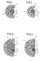
- a first embodiment of an inventive device shown in FIG. 1 insulated electrical overhead line cable has metallic conductors that are twisted into a bundle Wires 1, 2 exist.
- the metallic ladder can preferably be made of aluminum or an aluminum-containing one Alloy (so-called Aldrey wires) exist.
- the wires 1, 2 can preferably have a diameter or a non-round shape a cross-sectional dimension equivalent to the diameter in Have a range of about 5 to 15 mm.
- the cable has one made of a dielectric existing outer cable sheath surrounding the conductors 3 on, the wires 1 resting against the cable sheath 1 have such a cross-section deviating from the round shape, that the conductor surface adjoining the cable sheath 3 4 is designed almost without gussets. For this purpose and in order to increase the packing density of the wires 1 in the line, are compressed by pressing.
- the cable sheath 3 can advantageously be cross-linked, in particular made of flame-retardant Polyethylene (VPE) exist, the wall thickness of the cable jacket 3 preferably in the range of about 1 to 3 mm.
- VPE flame-retardant Polyethylene
- other materials are also especially other thermoplastics, can be used with advantage as materials for the cable sheath 3.
- a metal loose tube is in the overhead line cable according to the invention 5 arranged with integrated optical fibers 6.
- the metal loose tube 5 is pre-profiled in this way Sheathed wires 2 stranded that these sheathed wires 2nd an almost gap-free, segmented, electrically conductive, the metal loose tube 5 enclosing shell 7 form.
- the Sheathed wires 2 are surrounded by the pressed wires 1, the pressed wires 1 to the cable sheath form a bordering gusset-free conductor surface 4.
- the sheathed wires 2 preferably have the shape of an annulus segment in cross-section and thus form an annular sheath 7.
- Such a geometric cross-sectional shape of the sheath 7 has favorable, polar and axial, co-determining the mechanical strength of the line Area moments of inertia or also resistance moments, so that the sheath 7 provides optimal protection for the inside both in the case of torsion (stranding) or in the case of lateral pressure (pressing) as well as in the case of tension and bending (usual load case after assembly, wind load, ice load) Metal loose tube 5 forms.
- the metal loose tube 5 is in the first version as Central element stranded in the overhead line cable according to the invention. It should be longitudinally watertight against corrosion be what by introducing overhead line grease within the cross section enclosed by the cable sheath 3 of the overhead line cable can happen. Due to the smooth on Cable sheath 3 adjacent conductor surface 4 can in particular controlled flame cross-linking of a polyethylene material of the cable jacket 3 without complications, i.e. without any problems from melting or evaporating Bold, be done because near the cable jacket 3 the formation of any cavities in which fat could penetrate is excluded.
- the metal loose tube 5 has a metallic sleeve 8, the as protection and to relieve the strain on the optical fibers 6 serves.
- This sleeve 8 of the metal loose tube 5 can preferably be formed from a tube, the tube in particular a diameter of 1 to 4 mm and a Has wall thickness of 0.15 to 0.2 mm. It is manufacturing technology an advantage if the metal loose tube 5 made of tubular steel, especially stainless steel band is produced, which, preferably by means of a Lasers, is longitudinally welded. Inside the loose tube 5 can with radial play and especially with excess length compared to the sleeve 8, one or more, preferably 1 to 24 optical fibers 6 may be arranged. By game and excess length, for example, due to the weather Temperature fluctuations occurring different Linear expansion - or contraction of the metallic Sleeve 8 and the material of the optical fiber 6 bill carried.
- the sheathing wires 2 not surrounded by pressed wires 1 be, but the smooth on the cable jacket 3 Conductor surface 4 can also be through the cladding wires 2 be educated yourself.
- the manufacturing step of pressing can advantageously be omitted in this way.
- the third embodiment of an inventive Overhead cable illustrated goes shows that the loose tube 5 not only as a central element, but also in an asymmetrical stranded composite other wires within that of the pre-profiled Sheathed wires 2 formed segmented, electrical conductive sheath 7 can be stranded.
- this is Execution of a metal loose tube 5 with integrated optical fibers 6 and several round wires 9 within the Sheathing wires 2 arranged. Also several metal loose tubes 5 with integrated optical fibers 6 can together with the round wires 9 for stranding within the sheath 7 formed from the sheathed wires 2 is provided his. Instead of round wires 9, others can concentric wires are provided. This one too The manufacturing step of pressing can advantageously be carried out omitted, as the giddy training the conductor interface 4 on the cable jacket 3 through the profiled Sheathing wires 2 is achieved.
- the fourth embodiment (Fig. 4) of an inventive Overhead cable shows that the invention a wealth of possible combinations for design of an overhead line cable and thus a very broad spectrum for its area of application.
- this version are on the one hand - as in the third embodiment - A metal loose tube 5 with integrated optical fibers 6 and several round wires 9 within the Sheathed wires 2 arranged, on the other hand - as with first embodiment - the adjacent to the cable jacket 3 outer wires 1 compressed by pressing.
- this is Invention is not based on the illustrated embodiments limited, but also includes all in the sense of Invention equivalent effects.
- an overhead line according to the invention could also have several especially three or four, bundles of stranded wires 1, 2, 9 and metal loose tubes 5, each of one Cable sheath 3 are surrounded.
- the sheath 7 can also advantageously, for example the shape of a regular polygon.
- Such a geometric cross-sectional shape also has the Advantage of symmetry and extremely affordable polar and axial moments of inertia and resistance and allowed - as in the described exemplary embodiments - a form-fitting, almost space-free system of individual wires 1, 2, 9 and metal loose tube (s) 5 to each other.
- the expert can further useful features constructive design of an overhead line according to the invention, for example - as described at the beginning - one Phase identification by longitudinal knobs on the cable sheath 3, provide.
- Also against abrasion and corrosion protective cover for the metal loose tube 5 can additionally be provided.
- stranding wires 1, 2, 9 and the metal loose tube (s) 5 can preferably be a so-called Helical stranding, but also a different type of Stranding are used.
- the invention is not limited to that defined in claim 1 Characteristic combination limited, but can also through any other combination of certain Characteristics of all of the individual characteristics disclosed be defined. This means that basically practical each individual feature of claim 1 omitted or by at least one disclosed elsewhere in the application Single feature can be replaced. In this respect, the claim is 1 only as a first attempt at formulation for to understand an invention.
Landscapes
- Communication Cables (AREA)
- Insulated Conductors (AREA)
- Suspension Of Electric Lines Or Cables (AREA)
- Non-Insulated Conductors (AREA)
Abstract
Description
- Fig. 1
- einen Querschnitt durch eine erste Ausführung eines erfindungsgemäßen Freileitungskabels,
- Fig. 2
- einen Querschnitt durch eine zweite Ausführung eines erfindungsgemäßen Freileitungskabels,
- Fig. 3
- einen Querschnitt durch eine dritte Ausführung eines erfindungsgemäßen Freileitungskabels,
- Fig. 4
- einen Querschnitt durch eine vierte Ausführung eines erfindungsgemäßen Freileitungskabels.
Claims (15)
- Isoliertes elektrisches Freileitungskabel, mit metallischen Leitern, die aus zu mindestens einem Bündel verseilten Drähten (1, 2, 9) bestehen, und mit einem, aus einem Dielektrikum bestehenden, die Leiter umgebenden äußeren Kabelmantel (3), wobei zumindest die am Kabelmantel (3) anliegenden Drähte (1, 2) einen derart von der runden Form abweichenden Querschnitt aufweisen, daß eine an den Kabelmantel (3) grenzende Leiterfläche (4) nahezu zwickelfrei ausgebildet ist, gekennzeichnet durch mindestens eine Metallbündelader (5) mit mindestens einem integrierten Lichtwellenleiter (6), wobei die Metallbündelader (5) mit derart vorprofilierten Umhüllungsdrähten (2) verseilt ist, daß die Umhüllungsdrähte (2) eine segmentierte, elektrisch leitende, die Metallbündelader (5) umschließende Hülle (7) bilden.
- Freileitungskabel nach Anspruch 1,
dadurch gekennzeichnet, daß die Umhüllungsdrähte (2) jeweils im Querschnitt die Form eines Kreisring-Segments aufweisen und eine kreisringförmige Hülle (7) bilden. - Freileitungskabel nach Anspruch 1 oder 2,
dadurch gekennzeichnet, daß eine Metallbündelader (5) mit mindestens einem integrierten Lichtwellenleiter (6) mittig innerhalb der Umhüllungsdrähte (2) angeordnet ist. - Freileitungskabel nach Anspruch 1 oder 2,
dadurch gekennzeichnet, daß mindestens eine Metallbündelader (5) mit mindestens einem integrierten Lichtwellenleiter (6) sowie mehrere Runddrähte (9) innerhalb der Umhüllungsdrähte (2) angeordnet sind. - Freileitungskabel nach einem der Ansprüche 1 bis 4,
dadurch gekennzeichnet, daß die Umhüllungsdrähte (2) die an den Kabelmantel (3) grenzende Leiterfläche (4) bilden. - Freileitungskabel nach einem der Ansprüche 1 bis 4,
dadurch gekennzeichnet, daß die Umhüllungsdrähte (2) von verpreßten Drähten (1) umgeben sind, wobei die verpreßten Drähte (1) die an den Kabelmantel (3) grenzende Leiterfläche (4) bilden. - Freileitungskabel nach einem der Ansprüche 1 bis 6,
dadurch gekennzeichnet, daß der Kabelmantel (3) aus vernetzem, insbesondere flammvernetztem, Polyethylen (VPE) besteht. - Freileitungskabel nach einem der Ansprüche 1 bis 7,
dadurch gekennzeichnet, daß die metallischen Leiter aus Aluminium oder einer aluminiumhaltigen Legierung bestehen. - Freileitungskabel nach einem der Ansprüche 1 bis 8, gekennzeichnet durch mehrere, insbesondere drei oder vier, Bündel von verseilten Drähten (1, 2, 9) und Metallbündeladern (5) die jeweils von einem Kabelmantel (3) umgeben sind.
- Freileitungskabel nach einem der Ansprüche 1 bis 9,
dadurch gekennzeichnet, daß die Drähte (1, 2, 9) Durchmesser im Bereich von etwa 5 bis 15 mm aufweisen. - Freileitungskabel nach einem der Ansprüche 1 bis 10,
dadurch gekennzeichnet, daß der Kabelmantel (3) eine Wanddicke im Bereich von etwa 1 bis 3 mm aufweist. - Freileitungskabel nach einem der Ansprüche 1 bis 11,
dadurch gekennzeichnet, daß die Metallbündelader (5) längswasserdicht durch Fett korrosionsgeschützt ist. - Freileitungskabel nach einem der Ansprüche 1 bis 12,
dadurch gekennzeichnet, daß die Metallbündelader (5) eine aus einem Röhrchen gebildete Hülse (8) besitzt, wobei das Röhrchen insbesondere einen Durchmesser von 1 bis 4 mm und eine Wandstärke von 0,15 bis 0,2 mm aufweist. - Freileitungskabel nach einem der Ansprüche 1 bis 13,
dadurch gekennzeichnet, daß die Metallbündelader (5) aus rohrförmig geformten Stahlband hergestellt ist, das, insbesondere mittels eines Lasers, längsverschweißt ist. - Freileitungskabel nach einem der Ansprüche 1 bis 14, dadurch gekennzeichnet, daß innerhalb der Metallbündelader (5) mit radialem Spiel und insbesondere mit Überlänge gegenüber der Hülse (8), insbesondere 1 bis 24 Lichtwellenleiter angeordnet sind.
Applications Claiming Priority (2)
| Application Number | Priority Date | Filing Date | Title |
|---|---|---|---|
| DE29818646U | 1998-10-20 | ||
| DE29818646U DE29818646U1 (de) | 1998-10-20 | 1998-10-20 | Isoliertes elektrisches Freileitungskabel mit Lichtwellenleiter |
Publications (2)
| Publication Number | Publication Date |
|---|---|
| EP0996014A1 true EP0996014A1 (de) | 2000-04-26 |
| EP0996014B1 EP0996014B1 (de) | 2005-01-12 |
Family
ID=8064109
Family Applications (1)
| Application Number | Title | Priority Date | Filing Date |
|---|---|---|---|
| EP99121001A Expired - Lifetime EP0996014B1 (de) | 1998-10-20 | 1999-10-20 | Isoliertes elektrisches Freileitungskabel mit Lichtwellenleiter |
Country Status (3)
| Country | Link |
|---|---|
| EP (1) | EP0996014B1 (de) |
| AT (1) | ATE287094T1 (de) |
| DE (2) | DE29818646U1 (de) |
Cited By (1)
| Publication number | Priority date | Publication date | Assignee | Title |
|---|---|---|---|---|
| CN105679451A (zh) * | 2016-04-07 | 2016-06-15 | 江苏通光强能输电线科技有限公司 | 一种电缆温度在线监测用光纤复合导体 |
Families Citing this family (1)
| Publication number | Priority date | Publication date | Assignee | Title |
|---|---|---|---|---|
| CN114026658A (zh) * | 2019-06-28 | 2022-02-08 | 斯伦贝谢技术有限公司 | 机械响应性光纤线组件 |
Citations (2)
| Publication number | Priority date | Publication date | Assignee | Title |
|---|---|---|---|---|
| EP0407502A1 (de) * | 1988-12-05 | 1991-01-16 | Kupferdraht Isolierwerk Ag | Selbsttragendes optisches kabel. |
| JPH0447608A (ja) * | 1990-06-13 | 1992-02-17 | Fujikura Ltd | 耐雷性撚線 |
Family Cites Families (1)
| Publication number | Priority date | Publication date | Assignee | Title |
|---|---|---|---|---|
| JP3023906B2 (ja) * | 1996-02-08 | 2000-03-21 | 株式会社フジクラ | 電力線と光通信線を複合した架空地線 |
-
1998
- 1998-10-20 DE DE29818646U patent/DE29818646U1/de not_active Expired - Lifetime
-
1999
- 1999-10-20 AT AT99121001T patent/ATE287094T1/de not_active IP Right Cessation
- 1999-10-20 EP EP99121001A patent/EP0996014B1/de not_active Expired - Lifetime
- 1999-10-20 DE DE59911433T patent/DE59911433D1/de not_active Expired - Fee Related
Patent Citations (2)
| Publication number | Priority date | Publication date | Assignee | Title |
|---|---|---|---|---|
| EP0407502A1 (de) * | 1988-12-05 | 1991-01-16 | Kupferdraht Isolierwerk Ag | Selbsttragendes optisches kabel. |
| JPH0447608A (ja) * | 1990-06-13 | 1992-02-17 | Fujikura Ltd | 耐雷性撚線 |
Non-Patent Citations (1)
| Title |
|---|
| PATENT ABSTRACTS OF JAPAN vol. 016, no. 233 (E - 1209) 28 May 1992 (1992-05-28) * |
Cited By (1)
| Publication number | Priority date | Publication date | Assignee | Title |
|---|---|---|---|---|
| CN105679451A (zh) * | 2016-04-07 | 2016-06-15 | 江苏通光强能输电线科技有限公司 | 一种电缆温度在线监测用光纤复合导体 |
Also Published As
| Publication number | Publication date |
|---|---|
| ATE287094T1 (de) | 2005-01-15 |
| DE59911433D1 (de) | 2005-02-17 |
| DE29818646U1 (de) | 1999-02-11 |
| EP0996014B1 (de) | 2005-01-12 |
Similar Documents
| Publication | Publication Date | Title |
|---|---|---|
| DE3041679C2 (de) | ||
| DE69937112T2 (de) | Hybrides elektrisch-optisches kabel für freileitungsinstallationszwecke | |
| DE3513859C2 (de) | Unterwasser-Nachrichtenkabel mit mehreren optischen Fasern | |
| DE2820510A1 (de) | Flexibler verseilter koerper, insbesondere elektrischer freileiter | |
| DE3518909A1 (de) | Starkstromkabel, insbesondere fuer spannungen von 6 bis 60 kv, mit eingelegten lichtwellenleitern | |
| EP0126509A2 (de) | Optisches Kabelelement bzw. Kabel und Verfahren zu seiner Herstellung | |
| EP1162488A2 (de) | Optisches Luftkabel und zugehöriges Herstellungsverfahren | |
| EP0476438A2 (de) | Elektro-optisches Freileiterseil mit 24 und mehr Lichtwellenleitern | |
| CH656970A5 (de) | Hochflexibles isoliertes elektrisches kabel, verfahren zu seiner herstellung und verwendung des kabels. | |
| EP1199728A2 (de) | Isolierter elektrischer Leiter mit Funktionserhalt im Brandfall | |
| DE19549406C2 (de) | Verfahren zur Herstellung eines Sektorleiters für elektrische Energiekabel | |
| DE2815563A1 (de) | Optisches kabel | |
| EP1490881B1 (de) | Dreileiterkabel | |
| EP0253437A2 (de) | Elektrischer Freileiter mit einer optischen Nachrichtenleitung | |
| EP0042996B1 (de) | Selbsttragendes optisches Nachrichtenkabel | |
| DE3810746C2 (de) | Seekabel | |
| DE2801231A1 (de) | Elastomere-isolierte, elastomere- ummantelte starkstromtrosse, kabel, seil o.dgl. | |
| EP1653483A1 (de) | Mehradrige flexible elektrische Leitung | |
| EP0311751B1 (de) | Flexible Starkstromleitung, insbesondere Leitungstrosse, mit integrierten Lichtwellenleitern | |
| EP0996014B1 (de) | Isoliertes elektrisches Freileitungskabel mit Lichtwellenleiter | |
| DE2930643A1 (de) | Huelle fuer optische fasern | |
| DE2512830A1 (de) | Fernsehkamerakabel mit lichtleitfasern | |
| EP0221243A2 (de) | Lichtwellenleiter-Luftkabel | |
| DE19508888C2 (de) | Flexible elektrische Starkstromleitung | |
| DE2709106A1 (de) | Optisches kabel |
Legal Events
| Date | Code | Title | Description |
|---|---|---|---|
| PUAI | Public reference made under article 153(3) epc to a published international application that has entered the european phase |
Free format text: ORIGINAL CODE: 0009012 |
|
| AK | Designated contracting states |
Kind code of ref document: A1 Designated state(s): AT BE CH CY DE DK ES FI FR GB GR IE IT LI LU MC NL PT SE |
|
| AX | Request for extension of the european patent |
Free format text: AL PAYMENT 19991020;LT PAYMENT 19991020;LV PAYMENT 19991020;MK PAYMENT 19991020;RO PAYMENT 19991020;SI PAYMENT 19991020 |
|
| 17P | Request for examination filed |
Effective date: 20000407 |
|
| AKX | Designation fees paid |
Free format text: AT BE CH CY DE DK ES FI FR GB GR IE IT LI LU MC NL PT SE |
|
| AXX | Extension fees paid |
Free format text: AL PAYMENT 19991020;LT PAYMENT 19991020;LV PAYMENT 19991020;MK PAYMENT 19991020;RO PAYMENT 19991020;SI PAYMENT 19991020 |
|
| 17Q | First examination report despatched |
Effective date: 20030117 |
|
| RAP1 | Party data changed (applicant data changed or rights of an application transferred) |
Owner name: DRAKA TELECOM GMBH & CO.KG |
|
| GRAP | Despatch of communication of intention to grant a patent |
Free format text: ORIGINAL CODE: EPIDOSNIGR1 |
|
| GRAS | Grant fee paid |
Free format text: ORIGINAL CODE: EPIDOSNIGR3 |
|
| GRAA | (expected) grant |
Free format text: ORIGINAL CODE: 0009210 |
|
| AK | Designated contracting states |
Kind code of ref document: B1 Designated state(s): AT BE CH CY DE DK ES FI FR GB GR IE IT LI LU MC NL PT SE |
|
| AX | Request for extension of the european patent |
Extension state: AL LT LV MK RO SI |
|
| PG25 | Lapsed in a contracting state [announced via postgrant information from national office to epo] |
Ref country code: NL Free format text: LAPSE BECAUSE OF FAILURE TO SUBMIT A TRANSLATION OF THE DESCRIPTION OR TO PAY THE FEE WITHIN THE PRESCRIBED TIME-LIMIT Effective date: 20050112 Ref country code: IT Free format text: LAPSE BECAUSE OF FAILURE TO SUBMIT A TRANSLATION OF THE DESCRIPTION OR TO PAY THE FEE WITHIN THE PRE;WARNING: LAPSES OF ITALIAN PATENTS WITH EFFECTIVE DATE BEFORE 2007 MAY HAVE OCCURRED AT ANY TIME BEFORE 2007. THE CORRECT EFFECTIVE DATE MAY BE DIFFERENT FROM THE ONE RECORDED.SCRIBED TIME-LIMIT Effective date: 20050112 Ref country code: IE Free format text: LAPSE BECAUSE OF FAILURE TO SUBMIT A TRANSLATION OF THE DESCRIPTION OR TO PAY THE FEE WITHIN THE PRESCRIBED TIME-LIMIT Effective date: 20050112 Ref country code: GB Free format text: LAPSE BECAUSE OF FAILURE TO SUBMIT A TRANSLATION OF THE DESCRIPTION OR TO PAY THE FEE WITHIN THE PRESCRIBED TIME-LIMIT Effective date: 20050112 Ref country code: FR Free format text: LAPSE BECAUSE OF NON-PAYMENT OF DUE FEES Effective date: 20050112 Ref country code: FI Free format text: LAPSE BECAUSE OF FAILURE TO SUBMIT A TRANSLATION OF THE DESCRIPTION OR TO PAY THE FEE WITHIN THE PRESCRIBED TIME-LIMIT Effective date: 20050112 |
|
| REG | Reference to a national code |
Ref country code: GB Ref legal event code: FG4D Free format text: NOT ENGLISH |
|
| REG | Reference to a national code |
Ref country code: CH Ref legal event code: EP |
|
| REF | Corresponds to: |
Ref document number: 59911433 Country of ref document: DE Date of ref document: 20050217 Kind code of ref document: P |
|
| REG | Reference to a national code |
Ref country code: IE Ref legal event code: FG4D Free format text: GERMAN |
|
| PG25 | Lapsed in a contracting state [announced via postgrant information from national office to epo] |
Ref country code: SE Free format text: LAPSE BECAUSE OF FAILURE TO SUBMIT A TRANSLATION OF THE DESCRIPTION OR TO PAY THE FEE WITHIN THE PRESCRIBED TIME-LIMIT Effective date: 20050412 Ref country code: DK Free format text: LAPSE BECAUSE OF FAILURE TO SUBMIT A TRANSLATION OF THE DESCRIPTION OR TO PAY THE FEE WITHIN THE PRESCRIBED TIME-LIMIT Effective date: 20050412 |
|
| PG25 | Lapsed in a contracting state [announced via postgrant information from national office to epo] |
Ref country code: ES Free format text: LAPSE BECAUSE OF FAILURE TO SUBMIT A TRANSLATION OF THE DESCRIPTION OR TO PAY THE FEE WITHIN THE PRESCRIBED TIME-LIMIT Effective date: 20050423 |
|
| LTIE | Lt: invalidation of european patent or patent extension |
Effective date: 20050112 |
|
| NLV1 | Nl: lapsed or annulled due to failure to fulfill the requirements of art. 29p and 29m of the patents act | ||
| GBV | Gb: ep patent (uk) treated as always having been void in accordance with gb section 77(7)/1977 [no translation filed] |
Effective date: 20050112 |
|
| REG | Reference to a national code |
Ref country code: IE Ref legal event code: FD4D |
|
| PG25 | Lapsed in a contracting state [announced via postgrant information from national office to epo] |
Ref country code: CY Free format text: LAPSE BECAUSE OF FAILURE TO SUBMIT A TRANSLATION OF THE DESCRIPTION OR TO PAY THE FEE WITHIN THE PRESCRIBED TIME-LIMIT Effective date: 20051020 Ref country code: AT Free format text: LAPSE BECAUSE OF NON-PAYMENT OF DUE FEES Effective date: 20051020 |
|
| PG25 | Lapsed in a contracting state [announced via postgrant information from national office to epo] |
Ref country code: MC Free format text: LAPSE BECAUSE OF NON-PAYMENT OF DUE FEES Effective date: 20051031 Ref country code: LU Free format text: LAPSE BECAUSE OF NON-PAYMENT OF DUE FEES Effective date: 20051031 Ref country code: LI Free format text: LAPSE BECAUSE OF NON-PAYMENT OF DUE FEES Effective date: 20051031 Ref country code: CH Free format text: LAPSE BECAUSE OF NON-PAYMENT OF DUE FEES Effective date: 20051031 Ref country code: BE Free format text: LAPSE BECAUSE OF NON-PAYMENT OF DUE FEES Effective date: 20051031 |
|
| PLBE | No opposition filed within time limit |
Free format text: ORIGINAL CODE: 0009261 |
|
| STAA | Information on the status of an ep patent application or granted ep patent |
Free format text: STATUS: NO OPPOSITION FILED WITHIN TIME LIMIT |
|
| PGFP | Annual fee paid to national office [announced via postgrant information from national office to epo] |
Ref country code: DE Payment date: 20051219 Year of fee payment: 7 |
|
| 26N | No opposition filed |
Effective date: 20051013 |
|
| EN | Fr: translation not filed | ||
| REG | Reference to a national code |
Ref country code: CH Ref legal event code: PL |
|
| PG25 | Lapsed in a contracting state [announced via postgrant information from national office to epo] |
Ref country code: DE Free format text: LAPSE BECAUSE OF NON-PAYMENT OF DUE FEES Effective date: 20070501 |
|
| BERE | Be: lapsed |
Owner name: DRAKA TELEKOM G.M.B.H. & CO.KG Effective date: 20051031 |
|
| PG25 | Lapsed in a contracting state [announced via postgrant information from national office to epo] |
Ref country code: PT Free format text: LAPSE BECAUSE OF NON-PAYMENT OF DUE FEES Effective date: 20050612 |
|
| PG25 | Lapsed in a contracting state [announced via postgrant information from national office to epo] |
Ref country code: GR Free format text: LAPSE BECAUSE OF NON-PAYMENT OF DUE FEES Effective date: 20050112 |