EP0996013A2 - A holder for bundles of optical fibres - Google Patents
A holder for bundles of optical fibres Download PDFInfo
- Publication number
- EP0996013A2 EP0996013A2 EP99500190A EP99500190A EP0996013A2 EP 0996013 A2 EP0996013 A2 EP 0996013A2 EP 99500190 A EP99500190 A EP 99500190A EP 99500190 A EP99500190 A EP 99500190A EP 0996013 A2 EP0996013 A2 EP 0996013A2
- Authority
- EP
- European Patent Office
- Prior art keywords
- holder
- holder according
- main body
- filter
- bundle
- Prior art date
- Legal status (The legal status is an assumption and is not a legal conclusion. Google has not performed a legal analysis and makes no representation as to the accuracy of the status listed.)
- Granted
Links
Images


Classifications
-
- G—PHYSICS
- G02—OPTICS
- G02B—OPTICAL ELEMENTS, SYSTEMS OR APPARATUS
- G02B6/00—Light guides; Structural details of arrangements comprising light guides and other optical elements, e.g. couplings
- G02B6/24—Coupling light guides
- G02B6/36—Mechanical coupling means
- G02B6/40—Mechanical coupling means having fibre bundle mating means
-
- G—PHYSICS
- G02—OPTICS
- G02B—OPTICAL ELEMENTS, SYSTEMS OR APPARATUS
- G02B6/00—Light guides; Structural details of arrangements comprising light guides and other optical elements, e.g. couplings
- G02B6/44—Mechanical structures for providing tensile strength and external protection for fibres, e.g. optical transmission cables
- G02B6/4439—Auxiliary devices
- G02B6/4459—Ducts; Conduits; Hollow tubes for air blown fibres
- G02B6/4461—Articulated
-
- G—PHYSICS
- G02—OPTICS
- G02B—OPTICAL ELEMENTS, SYSTEMS OR APPARATUS
- G02B6/00—Light guides; Structural details of arrangements comprising light guides and other optical elements, e.g. couplings
- G02B6/04—Light guides; Structural details of arrangements comprising light guides and other optical elements, e.g. couplings formed by bundles of fibres
-
- G—PHYSICS
- G02—OPTICS
- G02B—OPTICAL ELEMENTS, SYSTEMS OR APPARATUS
- G02B6/00—Light guides; Structural details of arrangements comprising light guides and other optical elements, e.g. couplings
- G02B6/24—Coupling light guides
- G02B6/36—Mechanical coupling means
- G02B6/38—Mechanical coupling means having fibre to fibre mating means
- G02B6/3807—Dismountable connectors, i.e. comprising plugs
- G02B6/3887—Anchoring optical cables to connector housings, e.g. strain relief features
- G02B6/38875—Protection from bending or twisting
-
- G—PHYSICS
- G02—OPTICS
- G02B—OPTICAL ELEMENTS, SYSTEMS OR APPARATUS
- G02B6/00—Light guides; Structural details of arrangements comprising light guides and other optical elements, e.g. couplings
- G02B6/24—Coupling light guides
- G02B6/36—Mechanical coupling means
- G02B6/40—Mechanical coupling means having fibre bundle mating means
- G02B6/403—Mechanical coupling means having fibre bundle mating means of the ferrule type, connecting a pair of ferrules
Definitions
- the present invention relates to a holder for holding the ends of optical fibres constituting a bundle and for enabling them to be connected to a light-emitting device.
- Some of the currently known holders have a body in the form of a cap, in the closed end of which an opening is formed for the introduction of the end of the fibres into its interior.
- the diameter of the opening depends on the number of fibres constituting the bundle and therefore it has to be formed "in situ" by the fitter himself or at the factory.
- the optical fibres are held inside the cap by filling the space between the bundle formed by the optical fibres and the inner surface of the cap with an epoxy resin.
- the holder is connected to the outlet of the light-emitting device by pressing, the holder being kept in the connection position owing to the friction between its outer surface and the wall of the outlet.
- the holder forming the subject-matter of the present invention was devised in order to solve the problems discussed and comprises a main body having a tubular configuration, a filter-carrying ring, a sealing gasket, an element for clamping the gasket to be used, a flexible sleeve and a rear outlet mouth.
- the main body has, on the inside, a frustoconical front portion for positioning the chosen gasket, a threaded intermediate portion for mounting the element for clamping the gasket and a rear member or portion for holding the front end of the sleeve once pressed into the rear portion.
- the main body has, on the outside, a threaded front portion for mounting the filter-carrying ring and an intermediate portion provided with a plurality of peripheral mutually spaced and parallel channels; the purpose of the channels is to enable retractable stops provided in the outlet of the light-emitting device to be locked in any one of them; thus, the holder is prevented from being accidentally released from the light-emitting device, although it can be introduced to a greater or lesser extent into the outlet of the emitter in order to achieve adjustable control of the efficiency of the installation.
- Those channels define, in the main body, a number of ribs facilitating the dissipation of heat.
- the main body, the clamping element, the filter-carrying ring and the split rings are produced from a material having a high thermal conductivity and sufficient strength, for example aluminium.
- the filter-carrying ring which is screwed onto the front end of the main body, defines, on the inside, a stepped configuration which enables various filters to be mounted, and, at the front, an opening for the entry of the light coming from the emitter device towards the optical fibres, passing through the mentioned filters beforehand.
- the filters to be used are preferably an infrared interference filter, or a fine-layered dichroic filter, and a filter for absorbing ultraviolet rays; optionally, a thinner, third filter of gelatin may be positioned between them in order to change the colour temperature.
- the holder includes a sealing gasket which may comprise a set of split rings, each of which is formed by two or more portions.
- All of the rings have, on the outside, a frustoconical surface having an inclination equal to that defined in the main body; however, their inside diameters are different; that feature enables the same holder to be used for bundles having a larger or smaller number of optical fibres and therefore different diameters, it merely being necessary to mount in the holder the split ring whose nominal inside diameter is the one immediately larger than that of the fibre bundle.
- the element for clamping the selected ring has a tubular configuration in order to permit the passage of the bundle through its interior and is provided with a threaded portion enabling it to be mounted in the main body.
- the advance of the clamping element on the main body causes the portions constituting the split ring to be displaced on the frustoconical portion of the main body, thus causing them to approach one another diametrically and causing the optical fibres forming the bundle to be trapped, thus preventing them from being released.
- the gasket may also be constituted by a special form of silicone coil which can be fitted in the inner conical region of the body and on which pressure is exerted by a steel washer, preferably a nickel-plated steel washer, having a central drilled hole with a diameter suitable for the passage of the optical fibre cable.
- the nickel-plated steel washers have inside diameters which are variable within a mounting set and which enable the most suitable washer to be used in each case.
- the diameters of the washers are 15, 25 and 35 mm.
- the profiled section in the form of a silicone strip constitutes a continuous tape of relatively small width, for example 15 mm, which has self-centring characteristics, and its fitting, with a variable number of turns, permits the clamping of any optical fibre cable having a diameter of from 3 to 35 mm.
- the silicone profiled section is given a suitable length, for example 60 cm, in order to enable it to be adapted for the purpose of obtaining the appropriate holder for the smallest size of optical fibre cable for which the holder is intended.
- the length of the strip or profiled section of silicone is variable in accordance with the diameter of the optical fibre cable to which the holder is fitted.
- the rear region of the clamping element has diametrically opposed openings for the eventual positioning of a through-rod which facilitates its manual operation during mounting or dismounting with respect to the main body.
- the purpose of the flexible sleeve which is to be fitted to the rear region of the main body is to prevent damage to the fibres constituting the bundle if the bundle has to change direction at the outlet of the holder.
- the rear mouth of the holder is composed of an annular member which has, on the inside, a toothed portion for holding the rear end of the flexible sleeve and a frustoconical surface having a diameter which increases towards its rear region in order to facilitate the introduction of the fibres of the bundle into the holder and to prevent their accelerated deterioration once secured.
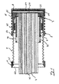
- Figure 1 is an elevation of the holder, sectioned on a vertical plane and mounted on a bundle of optical fibres.
- Figure 2 is an elevation of the holder coupled to the outlet of a light-emitting device; in this Figure, the sleeve is curved, the bundle of optical fibres changing direction at the outlet of the holder.
- Figure 3 is a part-sectioned detail of the main body of the holder.
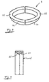
- Figure 4 is a perspective view of any one of the split rings that are to be mounted in the holder in order to hold the optical fibres constituting the bundle.
- Figure 5 is a part-sectioned detail of the rear mouth of the holder.
- Figure 6 is a view of a variant of the holder in longitudinal section, showing all of the integral elements in the mounted position.
- Figure 7 is a section on the plane indicated in Figure 6.
- Figure 8 is a view similar to Figure 6, representing the various component members of the holder in the dismounted state.
- the holder comprises a main body 1, a filter-carrying ring 2, a holding and sealing gasket, for example, in the form of a set of split rings 3, an element 4 for clamping the gasket mounted in the holder, a flexible sleeve 5 and a rear mouth 6.
- the purpose of the holder is to be mounted on the end of a bundle 7 of optical fibres 71 and to enable it to be coupled to the outlet 8 of a light-emitting device.
- the main body 1 has a frustoconical portion 11, a threaded intermediate portion 12, a rear portion 13 having a rough finish in order to improve adhesion, a threaded front portion 14 and a plurality of peripheral channels 15 which define ribs 16 on its outer surface.
- peripheral channels 15 The purpose of the peripheral channels 15 is to enable the holder to be locked by retractable stops 81 defined in the outlet 8 of the light-emitting device, it being possible to introduce the holder into the outlet 8 to a greater or lesser extent in order to vary the efficiency of the installation.
- the ribs 16, defined between the channels 15, facilitate heat dissipation by the holder.
- the filter-carrying ring 2 has a threaded portion 21 enabling it to be mounted on the main body 1 and a stepped configuration 22 for holding an infrared interference filter 23, a filter 24 for absorbing ultraviolet rays and optionally an intermediate filter 25 of gelatin.
- the bundle 7 is secured inside the holder by means of a gasket which in this case is in the form of split rings 3 positioned on the frustoconical portion 11 of the main body and which is pressed at its rear region by means of the clamping element 4.
- a gasket which in this case is in the form of split rings 3 positioned on the frustoconical portion 11 of the main body and which is pressed at its rear region by means of the clamping element 4.
- the rings 31 of the gasket have identical external frustoconical surfaces 32, having the same inclination as the portion 11 of the main body 1; however, they have different inside diameters.
- the gasket whose inside diameter is most suitable for clamping and immobilising the fibres 71 is mounted in the holder.
- the clamping element 4 has a threaded portion 41 which enables it to be mounted on the main body 1 in order to clamp the gasket 3.
- the latter has openings 42 into which a rod, a screwdriver or any other element acting as a lever can be introduced.
- the flexible sleeve 5 which is preferably produced from natural rubber, is pressed into the rear end of the main body 1, being held in the coupling position by the rough finish 13 together with an adhesive.
- the sleeve 5 prevents the optical fibres 71 from being flattened when the bundle 7 changes direction, as shown in Figure 2.
- a mouth 6 which has a rough coupling portion 61 is coupled, likewise with pressure, to the rear end of the sleeve 5.
- the sleeve has a frustoconical internal surface 62.
- the holder forming the subject-matter of the present invention comprises bellows of natural rubber 101 which are to permit transverse bending of the holder and protection of the fibres and which have, at the ends, smooth cylindrical end portions 102 and 103 on which respective collars 104 and 105 are fitted, the collars fitting onto the outside of the end portions 102 and 103, being joined by any suitable adhesive or means, for example, by an epoxy resin.
- the end internal portions of the collars are threaded, as indicated by the threaded region 106 of the collar 104, the collar 105 having an identical threaded region indicated by the numeral 107.
- the body 108 of the holder has a general cylindrical structure having an externally threaded end 109 so that it can fit in the internal thread of the collar 105, and having, at the other end, a narrowed portion which defines the opening 110 and an internal frustoconical region 111 which is to receive the specific means for sealing the cable, which will be explained hereinafter.
- the outside of the body 108 has a number of cooling slots 112 and its inside has a threaded region 113 which is to receive a clamping bush 114, the basic function of which is to act as a seal.
- the larger space between the first two grooves 125 and 126 is used to adjust the holder in such a manner that it can be directed more accurately.
- a gasket in the form of a strip 115 of a silicone profiled section of the self-centring type which has, for example, a stepped profile at its central portion, forming a projecting region 116 at its rear portion and a corresponding recessed region at its internal portion, which recessed region fits the projecting region 116 and is indicated by numeral 117 in Figure 8.
- the sealing tape can be adjusted to the length required inside the conical region 111 of the body 108 of the holder, depending on the final opening 118 which it is desired to obtain, in a manner appropriate to the diameter of the optical fibre cable.
- the silicone profiled unit 115 is fitted to the optical fibre cable by compression in the axial direction of the holder, for which purpose the holder has a pressure ring 119 which, at one face, rests on one side of the profiled unit 115 and, at the other face, receives the compression action of the bush 114.
- the bush 114 has a threaded external region 120 which is to be screwed into the inside of the body 108 of the holder, having means for its gradual clamping, for example, openings 121 for the introduction of a tool for rotating the bush 114.
- the bush 114 has a frustoconical end 122 which is supported on the intermediate ring 119 and exerts on the latter the pressure necessary to fit the silicone tape unit 115 to the end of the optical fibre cable.
- the external end portion 123 of the body 108 of the holder forming the subject-matter of the present invention is threaded so that it can receive the ring 124 which has an internal thread over part of its length and which is to hold different optical filters.
Abstract
Description
- The present invention relates to a holder for holding the ends of optical fibres constituting a bundle and for enabling them to be connected to a light-emitting device.
- Some of the currently known holders have a body in the form of a cap, in the closed end of which an opening is formed for the introduction of the end of the fibres into its interior.
- The diameter of the opening depends on the number of fibres constituting the bundle and therefore it has to be formed "in situ" by the fitter himself or at the factory.
- In that type of holder, the optical fibres are held inside the cap by filling the space between the bundle formed by the optical fibres and the inner surface of the cap with an epoxy resin.
- The holder is connected to the outlet of the light-emitting device by pressing, the holder being kept in the connection position owing to the friction between its outer surface and the wall of the outlet.
- Those holders have a number of problems among which the following should be pointed out:
- the drilling of the cap by the operator involves an increase in the time necessary for setting up the installation and therefore an increase in the cost thereof, especially if it is borne in mind that an installation may include a large number of holders;
- given that the application of epoxy resin in the mentioned region does not provide for any clamping of the optical fibres forming the bundle, those optical fibres which are positioned in cavities defined by adjacent optical fibres may come free from the holder, especially when the bundle includes fibres having different diameters and different degrees of hardness;
- at its rear end, the holder defines a rigid outlet and therefore, if the fibres have to change direction abruptly, some of them may be flattened or come free as mentioned above;
- when the holder is connected to the outlet of the light-emitting device by pressing, the end fibres may be spaced to a greater or lesser extent from the light source in a random manner, which involves an uncontrolled variation in the efficiency of the installation.
- Others of the mentioned holders are composed of a packing gland which, when tightened, brings about the deformation of a gasket having the task of exerting pressure on the optical fibres forming the bundle. Such holders have an advantage over the previous ones since they prevent the accidental release of the optical fibres; however, they have no means of solving the remainder of the problems posed above.
- The holder forming the subject-matter of the present invention was devised in order to solve the problems discussed and comprises a main body having a tubular configuration, a filter-carrying ring, a sealing gasket, an element for clamping the gasket to be used, a flexible sleeve and a rear outlet mouth.
- The main body has, on the inside, a frustoconical front portion for positioning the chosen gasket, a threaded intermediate portion for mounting the element for clamping the gasket and a rear member or portion for holding the front end of the sleeve once pressed into the rear portion.
- The main body has, on the outside, a threaded front portion for mounting the filter-carrying ring and an intermediate portion provided with a plurality of peripheral mutually spaced and parallel channels; the purpose of the channels is to enable retractable stops provided in the outlet of the light-emitting device to be locked in any one of them; thus, the holder is prevented from being accidentally released from the light-emitting device, although it can be introduced to a greater or lesser extent into the outlet of the emitter in order to achieve adjustable control of the efficiency of the installation.
- Those channels define, in the main body, a number of ribs facilitating the dissipation of heat. In order to facilitate heat dissipation, it has been provided that the main body, the clamping element, the filter-carrying ring and the split rings are produced from a material having a high thermal conductivity and sufficient strength, for example aluminium.
- The filter-carrying ring, which is screwed onto the front end of the main body, defines, on the inside, a stepped configuration which enables various filters to be mounted, and, at the front, an opening for the entry of the light coming from the emitter device towards the optical fibres, passing through the mentioned filters beforehand.
- In accordance with the invention, the filters to be used are preferably an infrared interference filter, or a fine-layered dichroic filter, and a filter for absorbing ultraviolet rays; optionally, a thinner, third filter of gelatin may be positioned between them in order to change the colour temperature.
- As mentioned above, the holder includes a sealing gasket which may comprise a set of split rings, each of which is formed by two or more portions.
- All of the rings have, on the outside, a frustoconical surface having an inclination equal to that defined in the main body; however, their inside diameters are different; that feature enables the same holder to be used for bundles having a larger or smaller number of optical fibres and therefore different diameters, it merely being necessary to mount in the holder the split ring whose nominal inside diameter is the one immediately larger than that of the fibre bundle.
- The element for clamping the selected ring has a tubular configuration in order to permit the passage of the bundle through its interior and is provided with a threaded portion enabling it to be mounted in the main body.
- The advance of the clamping element on the main body causes the portions constituting the split ring to be displaced on the frustoconical portion of the main body, thus causing them to approach one another diametrically and causing the optical fibres forming the bundle to be trapped, thus preventing them from being released.
- The gasket may also be constituted by a special form of silicone coil which can be fitted in the inner conical region of the body and on which pressure is exerted by a steel washer, preferably a nickel-plated steel washer, having a central drilled hole with a diameter suitable for the passage of the optical fibre cable.
- The nickel-plated steel washers have inside diameters which are variable within a mounting set and which enable the most suitable washer to be used in each case. In a preferred example, the diameters of the washers are 15, 25 and 35 mm.
- The profiled section in the form of a silicone strip constitutes a continuous tape of relatively small width, for example 15 mm, which has self-centring characteristics, and its fitting, with a variable number of turns, permits the clamping of any optical fibre cable having a diameter of from 3 to 35 mm. As a mounting unit with the holder, the silicone profiled section is given a suitable length, for example 60 cm, in order to enable it to be adapted for the purpose of obtaining the appropriate holder for the smallest size of optical fibre cable for which the holder is intended. The length of the strip or profiled section of silicone is variable in accordance with the diameter of the optical fibre cable to which the holder is fitted.
- The rear region of the clamping element has diametrically opposed openings for the eventual positioning of a through-rod which facilitates its manual operation during mounting or dismounting with respect to the main body.
- In accordance with the invention, the purpose of the flexible sleeve which is to be fitted to the rear region of the main body is to prevent damage to the fibres constituting the bundle if the bundle has to change direction at the outlet of the holder.
- The rear mouth of the holder is composed of an annular member which has, on the inside, a toothed portion for holding the rear end of the flexible sleeve and a frustoconical surface having a diameter which increases towards its rear region in order to facilitate the introduction of the fibres of the bundle into the holder and to prevent their accelerated deterioration once secured.
- In order to complement the description provided and to aid better understanding of the features of the invention, the present description is accompanied, as an integral part thereof, by a set of drawings in which the following has been represented by way of non-limiting example:
- Figure 1 is an elevation of the holder, sectioned on a vertical plane and mounted on a bundle of optical fibres.
- Figure 2 is an elevation of the holder coupled to the outlet of a light-emitting device; in this Figure, the sleeve is curved, the bundle of optical fibres changing direction at the outlet of the holder.
- Figure 3 is a part-sectioned detail of the main body of the holder.
- Figure 4 is a perspective view of any one of the split rings that are to be mounted in the holder in order to hold the optical fibres constituting the bundle.
- Figure 5 is a part-sectioned detail of the rear mouth of the holder.
- Figure 6 is a view of a variant of the holder in longitudinal section, showing all of the integral elements in the mounted position.
- Figure 7 is a section on the plane indicated in Figure 6.
- Figure 8 is a view similar to Figure 6, representing the various component members of the holder in the dismounted state.
- As shown in the Figures referred to, the holder comprises a
main body 1, a filter-carryingring 2, a holding and sealing gasket, for example, in the form of a set ofsplit rings 3, anelement 4 for clamping the gasket mounted in the holder, aflexible sleeve 5 and arear mouth 6. - The purpose of the holder is to be mounted on the end of a
bundle 7 ofoptical fibres 71 and to enable it to be coupled to the outlet 8 of a light-emitting device. - The
main body 1 has a frustoconical portion 11, a threadedintermediate portion 12, arear portion 13 having a rough finish in order to improve adhesion, a threadedfront portion 14 and a plurality ofperipheral channels 15 which defineribs 16 on its outer surface. - The purpose of the
peripheral channels 15 is to enable the holder to be locked by retractable stops 81 defined in the outlet 8 of the light-emitting device, it being possible to introduce the holder into the outlet 8 to a greater or lesser extent in order to vary the efficiency of the installation. - In their turn, the
ribs 16, defined between thechannels 15, facilitate heat dissipation by the holder. - The filter-carrying
ring 2 has a threadedportion 21 enabling it to be mounted on themain body 1 and astepped configuration 22 for holding aninfrared interference filter 23, afilter 24 for absorbing ultraviolet rays and optionally an intermediate filter 25 of gelatin. - The
bundle 7 is secured inside the holder by means of a gasket which in this case is in the form ofsplit rings 3 positioned on the frustoconical portion 11 of the main body and which is pressed at its rear region by means of theclamping element 4. - When the
portions 31 of the ring are displaced towards the front region of the holder, they approach one another owing to the conical shape of the portion 11, thus trapping thefibres 71. - The
rings 31 of the gasket have identical externalfrustoconical surfaces 32, having the same inclination as the portion 11 of themain body 1; however, they have different inside diameters. In accordance with the diameter of thebundle 7, the gasket whose inside diameter is most suitable for clamping and immobilising thefibres 71 is mounted in the holder. - The
clamping element 4 has a threaded portion 41 which enables it to be mounted on themain body 1 in order to clamp thegasket 3. In order to facilitate clamping by theelement 4, the latter has openings 42 into which a rod, a screwdriver or any other element acting as a lever can be introduced. - The
flexible sleeve 5, which is preferably produced from natural rubber, is pressed into the rear end of themain body 1, being held in the coupling position by therough finish 13 together with an adhesive. Thesleeve 5 prevents theoptical fibres 71 from being flattened when thebundle 7 changes direction, as shown in Figure 2. - A
mouth 6 which has arough coupling portion 61 is coupled, likewise with pressure, to the rear end of thesleeve 5. - In order to facilitate the introduction of the
optical fibres 71 into thesleeve 5, the sleeve has a frustoconicalinternal surface 62. - In the variant of Figures 6 to 8, the holder forming the subject-matter of the present invention comprises bellows of
natural rubber 101 which are to permit transverse bending of the holder and protection of the fibres and which have, at the ends, smoothcylindrical end portions respective collars end portions region 106 of thecollar 104, thecollar 105 having an identical threaded region indicated by thenumeral 107. - The
body 108 of the holder has a general cylindrical structure having an externally threadedend 109 so that it can fit in the internal thread of thecollar 105, and having, at the other end, a narrowed portion which defines theopening 110 and an internalfrustoconical region 111 which is to receive the specific means for sealing the cable, which will be explained hereinafter. The outside of thebody 108 has a number ofcooling slots 112 and its inside has a threadedregion 113 which is to receive aclamping bush 114, the basic function of which is to act as a seal. The larger space between the first twogrooves - In order to adapt the outlet opening to different optical fibre cables, a gasket in the form of a
strip 115 of a silicone profiled section of the self-centring type is provided which has, for example, a stepped profile at its central portion, forming aprojecting region 116 at its rear portion and a corresponding recessed region at its internal portion, which recessed region fits theprojecting region 116 and is indicated bynumeral 117 in Figure 8. The sealing tape can be adjusted to the length required inside theconical region 111 of thebody 108 of the holder, depending on thefinal opening 118 which it is desired to obtain, in a manner appropriate to the diameter of the optical fibre cable. - The silicone profiled
unit 115 is fitted to the optical fibre cable by compression in the axial direction of the holder, for which purpose the holder has apressure ring 119 which, at one face, rests on one side of the profiledunit 115 and, at the other face, receives the compression action of thebush 114. - As shown in the Figures, the
bush 114 has a threadedexternal region 120 which is to be screwed into the inside of thebody 108 of the holder, having means for its gradual clamping, for example,openings 121 for the introduction of a tool for rotating thebush 114. For improved coupling, thebush 114 has afrustoconical end 122 which is supported on theintermediate ring 119 and exerts on the latter the pressure necessary to fit thesilicone tape unit 115 to the end of the optical fibre cable. - The
external end portion 123 of thebody 108 of the holder forming the subject-matter of the present invention is threaded so that it can receive thering 124 which has an internal thread over part of its length and which is to hold different optical filters. - Further description is deemed unnecessary for an expert in the art to understand the scope of the invention and the advantages derived therefrom.
- The terms in which this specification has been written are always to be taken in the broad and non-limiting sense.
Claims (18)
- A holder for bundles of optical fibres, of the type that is to be positioned on the end of a bundle of optical fibres in order to couple it to the outlet of a light-emitting device, characterised in that it comprises a main body in which one end of the bundle of optical fibres is accommodated, a filter-carrying ring which is mounted on the front end of the main body, a gasket for holding and sealing the bundle of optical fibres inside the holder, depending on the diameter of the bundle, a clamping element which is mounted on the main body in order to clamp the gasket used, a flexible sleeve which is coupled to the rear end of the main body, and a rear mouth which is coupled to the rear end of the flexible sleeve.
- A holder according to the preceding claim, characterised in that the main body has, on the inside, a frustoconical portion on which the gasket is supported, a threaded intermediate portion for mounting the clamping element, and a rear portion for holding the front end of the flexible sleeve, once coupled to the main body.
- A holder according to the preceding claims, characterised in that the main body has, on the outside, a threaded front portion for mounting the filter-carrying ring, a plurality of peripheral channels for locking, in a variable position, retractable stops defined in the outlet of a light-emitting device, and peripheral ribs for the dissipation of heat.
- A holder according to the preceding claims, characterised in that the filter-carrying ring has a threaded portion enabling it to be mounted on the front end of the main body and an internal stepped configuration for holding an infrared interference filter, a filter for absorbing ultraviolet rays and, optionally, an intermediate filter of gelatin.
- A holder according to claim 1, characterised in that the sealing gasket is constituted by a number of split rings which can be coupled in a selective manner in order to hold and seal the bundle of optical fibres.
- A holder according to claim 5, characterised in that split rings belonging to the same set have, on the outside, identical frustoconical surfaces and, on the inside, different diameters.
- A holder according to claim 6, characterised in that the frustoconical surfaces of the split rings have an inclination identical to that of the portion of the main body.
- A holder according to claim 1, characterised in that the clamping element has, on the outside, a threaded portion that is to enable it to be mounted on the threaded portion of the main body.
- A holder according to claim 1, characterised in that the clamping element has, at the rear region, openings for positioning a rod acting as a lever, thus facilitating the manual clamping of the clamping element.
- A holder according to claim 1, characterised in that the rear mouth has a toothed portion that is to hold the rear end of the flexible sleeve in the coupling position and a frustoconical surface having a diameter which increases towards the rear region of the holder.
- A holder according to claim 1, characterised in that the body of the holder is capable of acting by way of an intermediate flat washer against the sealing gasket arranged in the internally conical end of the body of the holder.
- A holder according to claim 1, characterised in that the sealing gasket is composed of a strip of variable length which is adaptable to the actual diameter desired, and which strip is produced from a silicone material and is provided with a self-centring profile.
- A holder according to claim 1, characterised in that the element for clamping the sealing gasket has a short frustoconical end region directed towards the intermediate pressure washer in order to come into contact therewith.
- A holder according to claim 1, characterised in that end rings which can be coupled to the rubber bellows are identical for both ends of the profiled section.
- A holder according to claims 1 and 14, characterised in that the filter-carrying ring and the rear mouth are secured to the ends of the rubber bellows by means of an adhesive.
- A holder according to claim 15, characterised in that securing is effected by means of epoxy resins.
- A holder according to claim 12, characterised in that the self-centring silicone profiled section has, on its internal face, a recessed region and, on its external face, a projecting region which is capable of fitting in the recessed region of the profiled section.
- A holder according to claim 3, characterised in that the spacing between the first two channels is larger than between the other channels, in order to adjust the holder so that it can be directed more accurately.
Applications Claiming Priority (4)
| Application Number | Priority Date | Filing Date | Title |
|---|---|---|---|
| ES9802187 | 1998-10-20 | ||
| ES9802187A ES2168877B1 (en) | 1998-10-20 | 1998-10-20 | EMBOCADURA FOR DOES OF OPTICAL FIBER. |
| ES9900519A ES2168894B1 (en) | 1999-03-12 | 1999-03-12 | PERFECTED EMBOSSING FOR OPTICAL FIBER CABLES. |
| ES9900519 | 1999-03-12 |
Publications (3)
| Publication Number | Publication Date |
|---|---|
| EP0996013A2 true EP0996013A2 (en) | 2000-04-26 |
| EP0996013A3 EP0996013A3 (en) | 2003-05-14 |
| EP0996013B1 EP0996013B1 (en) | 2005-11-16 |
Family
ID=26155183
Family Applications (1)
| Application Number | Title | Priority Date | Filing Date |
|---|---|---|---|
| EP99500190A Expired - Lifetime EP0996013B1 (en) | 1998-10-20 | 1999-10-19 | A holder for bundles of optical fibres |
Country Status (4)
| Country | Link |
|---|---|
| US (1) | US6275635B1 (en) |
| EP (1) | EP0996013B1 (en) |
| AT (1) | ATE310253T1 (en) |
| DE (1) | DE69928351D1 (en) |
Cited By (3)
| Publication number | Priority date | Publication date | Assignee | Title |
|---|---|---|---|---|
| WO2003021555A2 (en) * | 2001-08-15 | 2003-03-13 | Optica Fibre Technologies Msc Sdn Bhd | Succession of corrected light guides for use in fiber optic display systems |
| GB2508907A (en) * | 2012-12-14 | 2014-06-18 | Gen Electric | Optical fibre alignment between ferrule and housing using tapered surfaces |
| WO2014179411A1 (en) * | 2013-05-03 | 2014-11-06 | Corning Optical Communications LLC | Fiber optic cable crimp assemblies employing integrally connected cable strain relief boots, and related fiber optic connectors, cables, and methods |
Families Citing this family (4)
| Publication number | Priority date | Publication date | Assignee | Title |
|---|---|---|---|---|
| KR20020032576A (en) * | 2000-07-10 | 2002-05-03 | 오카야마 노리오 | Optical fiber wire holder, fused connection device, cutting device, and method of connecting optical fiber |
| JP2005352167A (en) * | 2004-06-10 | 2005-12-22 | Fujikura Ltd | Butting device and fusion splicer equipped with the butting device |
| US20120267495A1 (en) * | 2011-03-21 | 2012-10-25 | Excelitas Technologies LED Solutions, Inc. | System and method for holding an optical rod |
| CN107861205A (en) * | 2017-11-16 | 2018-03-30 | 云南电网有限责任公司电力科学研究院 | A kind of fiber boot |
Citations (4)
| Publication number | Priority date | Publication date | Assignee | Title |
|---|---|---|---|---|
| US4620769A (en) * | 1982-12-29 | 1986-11-04 | Sumitomo Electric Industries, Ltd. | Image observation system |
| DE4003846A1 (en) * | 1989-02-10 | 1990-08-16 | Zelisko Josef Elektro Masch | Holder for optical fibre bunch - with wedge-type entry exerting radial clamping forces on bunch |
| WO1997048997A1 (en) * | 1996-06-18 | 1997-12-24 | Super Vision International, Inc. | Fiber optic light source apparatus and method |
| US5802227A (en) * | 1997-01-15 | 1998-09-01 | Pacfab, Inc. | Fiber optic end coupling for a lighting system |
Family Cites Families (4)
| Publication number | Priority date | Publication date | Assignee | Title |
|---|---|---|---|---|
| US4432602A (en) * | 1981-04-13 | 1984-02-21 | Trw, Inc. | Optical fiber clamp and connector assembly |
| JP2528095B2 (en) * | 1986-03-19 | 1996-08-28 | オリンパス光学工業株式会社 | Welding monitoring equipment |
| US5013125A (en) * | 1989-10-02 | 1991-05-07 | Alcatel Na Cable Systems Inc. | Pulling eye assembly for connectorized optical fiber cables |
| US5418874A (en) * | 1994-01-19 | 1995-05-23 | At&T Corp. | Force transfer system for an optical fiber connector |
-
1999
- 1999-10-19 EP EP99500190A patent/EP0996013B1/en not_active Expired - Lifetime
- 1999-10-19 US US09/420,246 patent/US6275635B1/en not_active Expired - Fee Related
- 1999-10-19 AT AT99500190T patent/ATE310253T1/en not_active IP Right Cessation
- 1999-10-19 DE DE69928351T patent/DE69928351D1/en not_active Expired - Lifetime
Patent Citations (4)
| Publication number | Priority date | Publication date | Assignee | Title |
|---|---|---|---|---|
| US4620769A (en) * | 1982-12-29 | 1986-11-04 | Sumitomo Electric Industries, Ltd. | Image observation system |
| DE4003846A1 (en) * | 1989-02-10 | 1990-08-16 | Zelisko Josef Elektro Masch | Holder for optical fibre bunch - with wedge-type entry exerting radial clamping forces on bunch |
| WO1997048997A1 (en) * | 1996-06-18 | 1997-12-24 | Super Vision International, Inc. | Fiber optic light source apparatus and method |
| US5802227A (en) * | 1997-01-15 | 1998-09-01 | Pacfab, Inc. | Fiber optic end coupling for a lighting system |
Cited By (6)
| Publication number | Priority date | Publication date | Assignee | Title |
|---|---|---|---|---|
| WO2003021555A2 (en) * | 2001-08-15 | 2003-03-13 | Optica Fibre Technologies Msc Sdn Bhd | Succession of corrected light guides for use in fiber optic display systems |
| WO2003021555A3 (en) * | 2001-08-15 | 2004-07-22 | Optica Fibre Technologies Msc | Succession of corrected light guides for use in fiber optic display systems |
| GB2508907A (en) * | 2012-12-14 | 2014-06-18 | Gen Electric | Optical fibre alignment between ferrule and housing using tapered surfaces |
| US9588309B2 (en) | 2012-12-14 | 2017-03-07 | General Electric Compnay | Optical fibre feedthrough assembly |
| WO2014179411A1 (en) * | 2013-05-03 | 2014-11-06 | Corning Optical Communications LLC | Fiber optic cable crimp assemblies employing integrally connected cable strain relief boots, and related fiber optic connectors, cables, and methods |
| US9429732B2 (en) | 2013-05-03 | 2016-08-30 | Corning Cable Systems Llc | Fiber optic cable crimp assemblies employing integrally connected cable strain relief boots, and related fiber optic connectors, cables, and methods |
Also Published As
| Publication number | Publication date |
|---|---|
| EP0996013B1 (en) | 2005-11-16 |
| DE69928351D1 (en) | 2005-12-22 |
| US6275635B1 (en) | 2001-08-14 |
| EP0996013A3 (en) | 2003-05-14 |
| ATE310253T1 (en) | 2005-12-15 |
Similar Documents
| Publication | Publication Date | Title |
|---|---|---|
| US4964685A (en) | Connector with precision fiber optic alignment clamp | |
| AU759995B2 (en) | An optical fiber cable inlet device | |
| US4744622A (en) | Optical fiber splice case | |
| US20180003202A1 (en) | Swagless turnbuckle assembly | |
| US6053639A (en) | Optic fiber inner tube connector | |
| GB2091498A (en) | A device for holding cables | |
| US4378172A (en) | Telescopically adjustable support particularly for a camera tripod | |
| EP0996013B1 (en) | A holder for bundles of optical fibres | |
| JPS6052353B2 (en) | Methods and fittings for protecting the ends of tubular conduits | |
| US6605781B2 (en) | Cable guide for a sealed box, and a sealing assembly including such a guide | |
| US4664471A (en) | Junction box for joining the ends of underwater optical fiber cables by welding | |
| EP1448924B1 (en) | Sleeve of a gland assembly | |
| AU670106B2 (en) | Cable gland | |
| CA2139852C (en) | Fluid line connector fitting | |
| GB2042755A (en) | An optical fibre connector | |
| US3011745A (en) | Clamp for supporting wires or conduits | |
| CA1162176A (en) | Anchoring and sealing coupling for a cable | |
| US2694584A (en) | Coupling | |
| US4178021A (en) | Leak-tight coupling device | |
| AU669374B2 (en) | An arrangement for multiple cable introductions in cable sleeves | |
| GB2085992A (en) | Improvements in or relating to releasable tube couplings | |
| HU212139B (en) | Sealing element for cable bundles laid into cable duct | |
| GB2269710A (en) | Cable gland | |
| GB2333818A (en) | Device for the sealed laying of tubes | |
| KR102155070B1 (en) | Cable gland with heat shrinkable tube |
Legal Events
| Date | Code | Title | Description |
|---|---|---|---|
| PUAI | Public reference made under article 153(3) epc to a published international application that has entered the european phase |
Free format text: ORIGINAL CODE: 0009012 |
|
| AK | Designated contracting states |
Kind code of ref document: A2 Designated state(s): AT BE CH CY DE DK ES FI FR GB GR IE IT LI LU MC NL PT SE |
|
| AX | Request for extension of the european patent |
Free format text: AL;LT;LV;MK;RO;SI |
|
| PUAL | Search report despatched |
Free format text: ORIGINAL CODE: 0009013 |
|
| AK | Designated contracting states |
Designated state(s): AT BE CH CY DE DK ES FI FR GB GR IE IT LI LU MC NL PT SE |
|
| AX | Request for extension of the european patent |
Extension state: AL LT LV MK RO SI |
|
| RIC1 | Information provided on ipc code assigned before grant |
Ipc: 7G 02B 6/36 B Ipc: 7G 02B 6/40 A |
|
| 17P | Request for examination filed |
Effective date: 20031103 |
|
| AKX | Designation fees paid |
Designated state(s): AT BE CH CY DE DK ES FI FR GB GR IE IT LI LU MC NL PT SE |
|
| 17Q | First examination report despatched |
Effective date: 20040114 |
|
| GRAP | Despatch of communication of intention to grant a patent |
Free format text: ORIGINAL CODE: EPIDOSNIGR1 |
|
| GRAS | Grant fee paid |
Free format text: ORIGINAL CODE: EPIDOSNIGR3 |
|
| GRAA | (expected) grant |
Free format text: ORIGINAL CODE: 0009210 |
|
| AK | Designated contracting states |
Kind code of ref document: B1 Designated state(s): AT BE CH CY DE DK ES FI FR GB GR IE IT LI LU MC NL PT SE |
|
| PG25 | Lapsed in a contracting state [announced via postgrant information from national office to epo] |
Ref country code: NL Free format text: LAPSE BECAUSE OF FAILURE TO SUBMIT A TRANSLATION OF THE DESCRIPTION OR TO PAY THE FEE WITHIN THE PRESCRIBED TIME-LIMIT Effective date: 20051116 Ref country code: LI Free format text: LAPSE BECAUSE OF FAILURE TO SUBMIT A TRANSLATION OF THE DESCRIPTION OR TO PAY THE FEE WITHIN THE PRESCRIBED TIME-LIMIT Effective date: 20051116 Ref country code: IT Free format text: LAPSE BECAUSE OF FAILURE TO SUBMIT A TRANSLATION OF THE DESCRIPTION OR TO PAY THE FEE WITHIN THE PRESCRIBED TIME-LIMIT;WARNING: LAPSES OF ITALIAN PATENTS WITH EFFECTIVE DATE BEFORE 2007 MAY HAVE OCCURRED AT ANY TIME BEFORE 2007. THE CORRECT EFFECTIVE DATE MAY BE DIFFERENT FROM THE ONE RECORDED. Effective date: 20051116 Ref country code: FI Free format text: LAPSE BECAUSE OF FAILURE TO SUBMIT A TRANSLATION OF THE DESCRIPTION OR TO PAY THE FEE WITHIN THE PRESCRIBED TIME-LIMIT Effective date: 20051116 Ref country code: CH Free format text: LAPSE BECAUSE OF FAILURE TO SUBMIT A TRANSLATION OF THE DESCRIPTION OR TO PAY THE FEE WITHIN THE PRESCRIBED TIME-LIMIT Effective date: 20051116 Ref country code: BE Free format text: LAPSE BECAUSE OF FAILURE TO SUBMIT A TRANSLATION OF THE DESCRIPTION OR TO PAY THE FEE WITHIN THE PRESCRIBED TIME-LIMIT Effective date: 20051116 Ref country code: AT Free format text: LAPSE BECAUSE OF FAILURE TO SUBMIT A TRANSLATION OF THE DESCRIPTION OR TO PAY THE FEE WITHIN THE PRESCRIBED TIME-LIMIT Effective date: 20051116 |
|
| REG | Reference to a national code |
Ref country code: GB Ref legal event code: FG4D |
|
| REG | Reference to a national code |
Ref country code: CH Ref legal event code: EP |
|
| REG | Reference to a national code |
Ref country code: IE Ref legal event code: FG4D |
|
| REF | Corresponds to: |
Ref document number: 69928351 Country of ref document: DE Date of ref document: 20051222 Kind code of ref document: P |
|
| PG25 | Lapsed in a contracting state [announced via postgrant information from national office to epo] |
Ref country code: SE Free format text: LAPSE BECAUSE OF FAILURE TO SUBMIT A TRANSLATION OF THE DESCRIPTION OR TO PAY THE FEE WITHIN THE PRESCRIBED TIME-LIMIT Effective date: 20060216 Ref country code: GR Free format text: LAPSE BECAUSE OF FAILURE TO SUBMIT A TRANSLATION OF THE DESCRIPTION OR TO PAY THE FEE WITHIN THE PRESCRIBED TIME-LIMIT Effective date: 20060216 Ref country code: DK Free format text: LAPSE BECAUSE OF FAILURE TO SUBMIT A TRANSLATION OF THE DESCRIPTION OR TO PAY THE FEE WITHIN THE PRESCRIBED TIME-LIMIT Effective date: 20060216 |
|
| PG25 | Lapsed in a contracting state [announced via postgrant information from national office to epo] |
Ref country code: DE Free format text: LAPSE BECAUSE OF FAILURE TO SUBMIT A TRANSLATION OF THE DESCRIPTION OR TO PAY THE FEE WITHIN THE PRESCRIBED TIME-LIMIT Effective date: 20060217 |
|
| PG25 | Lapsed in a contracting state [announced via postgrant information from national office to epo] |
Ref country code: ES Free format text: LAPSE BECAUSE OF FAILURE TO SUBMIT A TRANSLATION OF THE DESCRIPTION OR TO PAY THE FEE WITHIN THE PRESCRIBED TIME-LIMIT Effective date: 20060227 |
|
| PG25 | Lapsed in a contracting state [announced via postgrant information from national office to epo] |
Ref country code: PT Free format text: LAPSE BECAUSE OF FAILURE TO SUBMIT A TRANSLATION OF THE DESCRIPTION OR TO PAY THE FEE WITHIN THE PRESCRIBED TIME-LIMIT Effective date: 20060417 |
|
| NLV1 | Nl: lapsed or annulled due to failure to fulfill the requirements of art. 29p and 29m of the patents act | ||
| REG | Reference to a national code |
Ref country code: CH Ref legal event code: PL |
|
| PLBE | No opposition filed within time limit |
Free format text: ORIGINAL CODE: 0009261 |
|
| STAA | Information on the status of an ep patent application or granted ep patent |
Free format text: STATUS: NO OPPOSITION FILED WITHIN TIME LIMIT |
|
| PG25 | Lapsed in a contracting state [announced via postgrant information from national office to epo] |
Ref country code: IE Free format text: LAPSE BECAUSE OF NON-PAYMENT OF DUE FEES Effective date: 20061019 |
|
| 26N | No opposition filed |
Effective date: 20060817 |
|
| PG25 | Lapsed in a contracting state [announced via postgrant information from national office to epo] |
Ref country code: MC Free format text: LAPSE BECAUSE OF NON-PAYMENT OF DUE FEES Effective date: 20061031 |
|
| EN | Fr: translation not filed | ||
| GBPC | Gb: european patent ceased through non-payment of renewal fee |
Effective date: 20061019 |
|
| REG | Reference to a national code |
Ref country code: IE Ref legal event code: MM4A |
|
| PG25 | Lapsed in a contracting state [announced via postgrant information from national office to epo] |
Ref country code: GB Free format text: LAPSE BECAUSE OF NON-PAYMENT OF DUE FEES Effective date: 20061019 |
|
| PG25 | Lapsed in a contracting state [announced via postgrant information from national office to epo] |
Ref country code: FR Free format text: LAPSE BECAUSE OF FAILURE TO SUBMIT A TRANSLATION OF THE DESCRIPTION OR TO PAY THE FEE WITHIN THE PRESCRIBED TIME-LIMIT Effective date: 20070105 |
|
| PG25 | Lapsed in a contracting state [announced via postgrant information from national office to epo] |
Ref country code: LU Free format text: LAPSE BECAUSE OF NON-PAYMENT OF DUE FEES Effective date: 20061019 |
|
| PG25 | Lapsed in a contracting state [announced via postgrant information from national office to epo] |
Ref country code: FR Free format text: LAPSE BECAUSE OF FAILURE TO SUBMIT A TRANSLATION OF THE DESCRIPTION OR TO PAY THE FEE WITHIN THE PRESCRIBED TIME-LIMIT Effective date: 20051116 Ref country code: CY Free format text: LAPSE BECAUSE OF FAILURE TO SUBMIT A TRANSLATION OF THE DESCRIPTION OR TO PAY THE FEE WITHIN THE PRESCRIBED TIME-LIMIT Effective date: 20051116 |