EP0995115B1 - Dispositif de surveillance de la qualite de l'air - Google Patents
Dispositif de surveillance de la qualite de l'air Download PDFInfo
- Publication number
- EP0995115B1 EP0995115B1 EP97933668A EP97933668A EP0995115B1 EP 0995115 B1 EP0995115 B1 EP 0995115B1 EP 97933668 A EP97933668 A EP 97933668A EP 97933668 A EP97933668 A EP 97933668A EP 0995115 B1 EP0995115 B1 EP 0995115B1
- Authority
- EP
- European Patent Office
- Prior art keywords
- sensor
- sensor arrangement
- measuring
- air quality
- measured values
- Prior art date
- Legal status (The legal status is an assumption and is not a legal conclusion. Google has not performed a legal analysis and makes no representation as to the accuracy of the status listed.)
- Expired - Lifetime
Links
- 238000012544 monitoring process Methods 0.000 title claims description 14
- 239000007789 gas Substances 0.000 claims description 28
- 238000005259 measurement Methods 0.000 claims description 12
- 239000012855 volatile organic compound Substances 0.000 claims description 11
- CURLTUGMZLYLDI-UHFFFAOYSA-N Carbon dioxide Chemical compound O=C=O CURLTUGMZLYLDI-UHFFFAOYSA-N 0.000 claims description 9
- 229910002092 carbon dioxide Inorganic materials 0.000 claims description 6
- 230000015654 memory Effects 0.000 claims description 6
- 229910002091 carbon monoxide Inorganic materials 0.000 claims description 5
- 230000009471 action Effects 0.000 claims description 4
- 230000001590 oxidative effect Effects 0.000 claims description 4
- 230000008447 perception Effects 0.000 claims description 4
- 239000000126 substance Substances 0.000 claims description 4
- 239000001569 carbon dioxide Substances 0.000 claims description 3
- 239000000203 mixture Substances 0.000 claims 2
- 238000005070 sampling Methods 0.000 description 7
- 230000006870 function Effects 0.000 description 5
- UGFAIRIUMAVXCW-UHFFFAOYSA-N Carbon monoxide Chemical compound [O+]#[C-] UGFAIRIUMAVXCW-UHFFFAOYSA-N 0.000 description 4
- 230000008859 change Effects 0.000 description 4
- VNWKTOKETHGBQD-UHFFFAOYSA-N methane Chemical compound C VNWKTOKETHGBQD-UHFFFAOYSA-N 0.000 description 4
- 238000009423 ventilation Methods 0.000 description 4
- 238000000034 method Methods 0.000 description 3
- CSCPPACGZOOCGX-UHFFFAOYSA-N Acetone Chemical compound CC(C)=O CSCPPACGZOOCGX-UHFFFAOYSA-N 0.000 description 2
- 239000001273 butane Substances 0.000 description 2
- 238000001514 detection method Methods 0.000 description 2
- 238000010586 diagram Methods 0.000 description 2
- IJDNQMDRQITEOD-UHFFFAOYSA-N n-butane Chemical compound CCCC IJDNQMDRQITEOD-UHFFFAOYSA-N 0.000 description 2
- OFBQJSOFQDEBGM-UHFFFAOYSA-N n-pentane Natural products CCCCC OFBQJSOFQDEBGM-UHFFFAOYSA-N 0.000 description 2
- ZKATWMILCYLAPD-UHFFFAOYSA-N niobium pentoxide Chemical compound O=[Nb](=O)O[Nb](=O)=O ZKATWMILCYLAPD-UHFFFAOYSA-N 0.000 description 2
- XOLBLPGZBRYERU-UHFFFAOYSA-N tin dioxide Chemical compound O=[Sn]=O XOLBLPGZBRYERU-UHFFFAOYSA-N 0.000 description 2
- 230000002159 abnormal effect Effects 0.000 description 1
- 230000001476 alcoholic effect Effects 0.000 description 1
- 230000003321 amplification Effects 0.000 description 1
- QVGXLLKOCUKJST-UHFFFAOYSA-N atomic oxygen Chemical compound [O] QVGXLLKOCUKJST-UHFFFAOYSA-N 0.000 description 1
- 238000009795 derivation Methods 0.000 description 1
- 230000000694 effects Effects 0.000 description 1
- 239000001257 hydrogen Substances 0.000 description 1
- 229910052739 hydrogen Inorganic materials 0.000 description 1
- 125000004435 hydrogen atom Chemical class [H]* 0.000 description 1
- 238000003199 nucleic acid amplification method Methods 0.000 description 1
- 239000001301 oxygen Substances 0.000 description 1
- 229910052760 oxygen Inorganic materials 0.000 description 1
- 230000008569 process Effects 0.000 description 1
- 230000002441 reversible effect Effects 0.000 description 1
- 230000035945 sensitivity Effects 0.000 description 1
- 239000000779 smoke Substances 0.000 description 1
- 239000002341 toxic gas Substances 0.000 description 1
Images

Classifications
-
- G—PHYSICS
- G01—MEASURING; TESTING
- G01N—INVESTIGATING OR ANALYSING MATERIALS BY DETERMINING THEIR CHEMICAL OR PHYSICAL PROPERTIES
- G01N33/00—Investigating or analysing materials by specific methods not covered by groups G01N1/00 - G01N31/00
- G01N33/0004—Gaseous mixtures, e.g. polluted air
- G01N33/0009—General constructional details of gas analysers, e.g. portable test equipment
- G01N33/0062—General constructional details of gas analysers, e.g. portable test equipment concerning the measuring method or the display, e.g. intermittent measurement or digital display
-
- G—PHYSICS
- G01—MEASURING; TESTING
- G01D—MEASURING NOT SPECIALLY ADAPTED FOR A SPECIFIC VARIABLE; ARRANGEMENTS FOR MEASURING TWO OR MORE VARIABLES NOT COVERED IN A SINGLE OTHER SUBCLASS; TARIFF METERING APPARATUS; MEASURING OR TESTING NOT OTHERWISE PROVIDED FOR
- G01D7/00—Indicating measured values
- G01D7/02—Indicating value of two or more variables simultaneously
Definitions
- This invention concerns a device in accordance with Claim 1.
- the invention as claimed aims at solving the above described problems with state of the art devices and to allow indication of air quality history which allows the user to take appropriate measures for improving air quality or to avoid uncomfortable or dangerous situations.
- the present invention provides a device for monitoring the air quality as defined in Claim 1.
- the device 1 for monitoring the air quality is illustrated in Figs. 2, 3, 7 - 9.
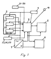
- the function of the device 1 can best be described having reference to the block circuit diagram represented in detail in Figure 1.
- It contains a sensor arrangement 2 for measuring a variety of chemical gases and of meteorological parameters which play an influential part in perception of air quality comfort.
- Said arrangement 2 comprises at least one of the following gas sensors:
- Gas sensors of the above type are commercially available and well known in the art.
- Gas sensors for reducing and oxidizing gases are based on reversible conductivity change of the sensing elements and are able to detect a variety of gases.
- Sensors with SnO 2 sensitive layers are able to detect most reducing gases, e.g. combustible gases (hydrogen, methane, butane a.s.o.), toxic gases (CO, NO x ), alcoholic and cetonic vapours.
- Sensors with Nb 2 O 5 sensitive layers are able to detect most oxidizing gases, e.g. oxygen and NO 2 .
- Sensors for VOC gases are based on thermal conductivity.
- VOC gases volatile organic compounds
- VOC gases may comprise butane, methane, ethanolic vapours, smelling gases generated by smoke and other burning processes.
- Additional sensors for meteorological data may be used in the device, such as a temperature sensor 27, a barometric pressure sensor 28 and/or a relative air humidity sensor 29.
- the outputs from the sensors 21-29 are fed to a computer 3 which is connected to an electronic clock 4, a memory 5 and indicating arrangements 6.
- a current supply system 7 supplies all the parts of the device with power.
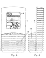
- the indicating arrangements 6 consist basically of four displays.
- Display 61 indicates current temperature
- display 62 indicates relative humidity
- display 63 indicates the air quality in form of a bar chart distinguishing between "very poor”, “poor”, “fair” and “good” air quality.
- Display 64 indicates symbols for proposed or recommended actions/measures to be taken by the user. From left to right the following symbols are available:
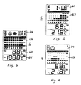
- a condition of "very poor” air quality is indicated on the indicating arrangements 6.
- Display 64 shows the fan turning and the window open.
- the bar chart indicates the actual "very poor” condition in the bar column at the extreme right in display 63.
- the bar column left from the extreme right column indicates the air condition 1 minute ago, which was “poor”. Further left the next column shows the air condition 2 minutes ago which was “fair”. The next columns to the left show the air condition 3 minutes, 4 minutes and 6 minutes ago which was still “fair”. The next columns to the left show the air condition 8, 10 and 15 minutes ago which was "good”.
- the above measurement intervals are indicated only as an example. They are, however, small compared with the said period of time (1 to 10 % thereof) and typically in the range of 0,5 to 2,0 minutes, preferably of 0,9 to 1,1 minutes, for measuring short term events.
- a condition of "good” air quality is indicated on the indicating arrangements 6.
- Display 64 shows the face smiling only.
- the bar chart indicates the actual "good” air quality condition in the bar column at the extreme right in display 63.
- the bar column left from the extreme right column indicates the air condition 1/4 of an hour ago, which was still "good”. Further left the next column shows the air condition 1/2 hour ago which was still "good”. The next columns to the left show the air condition 3/4, 1, 1,5 and 2 hours ago which was “fair”. The next columns to the left show the air condition 4 and 6 hours ago which was "good”.
- the display 64 in Fig. 6 shows therefore - when the measured values remain constant for a certain time period - that the measurement mode is automatically switched to longer intervals in the range of 10 to 20 minutes, preferably of 14 to 16 minutes, for measuring medium term events. This procedure helps to minimize power consumption which is particularly important when the device is battery operated. As soon as measured values are significantly changing - or alternatively by acting on an appropriate button 10 (Fig. 8) of the device 1 - the operation mode of the device is again switched to the short term event measurement.
- the history bargraphs display in display 64 of the indicating arrangements 6 may comprise the following:
- Part of the computer 3 is set up as an algorithm producer which deduces symbols for the level of air quality from measured values and/or measured values trends fed into the computer 3. Said symbols can be displayed for the level of air quality at the indicating arrangements 6 which are shown in detail in Figs. 4 to 6.
- the sensor arrangement 2 may comprise two sensors for each parameter (chemical gas or meteorological data) to be measured, one sensor for indoor measurement and one sensor for outdoor measurement.
- one sensor for indoor measurement may use an indoor sensor 24 for the detection of carbon monoxide CO and an outdoor sensor 34 for the detection of carbon monoxide CO.
- This double measurement allows to give the user indications about opportunity of opening the window in order to enhance air quality.
- By appropriate symbols on the indicating arrangements 6 the user may be alerted not to open the window because outdoor conditions are not recommending such an action.
- the device 1 allows therefore useful indication, at the indicating arrangements 6, whether comfortable and/or safe conditions prevail indoor in the room in which the device 1 is set up, compared to the outdoor conditions.
- the device 1 generates by means of algorithms and displays on the indicating arrangements 6 by means of symbols or icons recommended actions to be performed by the user of the device, e.g.
- the indication of air quality comfort and its numerical or symbolic display on the indicating arrangements 6 can be adjusted to individual perception by lowering or increasing threshold-values triggering changes in the display. This additional feature is of great importance since the human nose is recognized universally to be the best sensor. The device is able by this means to match individual perception of air quality comfort which may vary tremendously from one person to the other ("user accepted level").
- the device according to the invention may comprise different combinations of sensors according to the intended use of the device.
- a very simple device may consist of an indoor sensor 21 for VOC an indoor temperature sensor 27 and an outdoor temperature sensor 37.
- a more sophisticated device may consist of indoor sensors 21 for VOC, 22 for measuring carbon dioxide CO 2 , 23 for measuring nitric oxides NO x and 27 for measuring indoor temperature, as well as of outdoor sensors 37 for measuring outdoor temperature and 33 for measuring outdoor concentration of nitric oxides NO x .
- the device 1 may consist of indoor sensors 23 for measuring nitric oxides NO x , 24 for carbon monoxide and 27 for measuring indoor temperature, as well as of outdoor sensors 37 for outdoor temperature, 33 for outdoor concentration of nitric oxides NO x and 34 for outdoor monoxide concentration.
- the device 1 can be designed in several ways. One embodiment is shown in Figs. 2, 3, 7 - 9. Its front with the indicating arrangements 6 is explained above in detail as represented in Fig. 2.
- Fig. 3 shows a lateral view of device 1 with a number of ventilation slots 11 for allowing circulation of air within the device 1 and allowing in particular access of the air to the sensors 21-26.
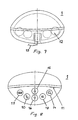
- Fig. 7 shows a bottom view of device 1 with four cavities 12 for receiving batteries and a DC power jack 13 for attachment to an electric source 7.
- Fig. 8 shows a top view of device 1 with ventilation slots 11 and a number of function keys which are explained from right to left:
- Fig. 9 shows a back view of the device 1 with the DC power jack 13 for attachment to an electric source 7, the four cavities 12 for receiving batteries, and a number of ventilation slots 11.
- the rear key panel 65 four buttons can be distinguished from right to left:
Landscapes
- Chemical & Material Sciences (AREA)
- Physics & Mathematics (AREA)
- Engineering & Computer Science (AREA)
- General Physics & Mathematics (AREA)
- Health & Medical Sciences (AREA)
- Life Sciences & Earth Sciences (AREA)
- Analytical Chemistry (AREA)
- Medicinal Chemistry (AREA)
- Food Science & Technology (AREA)
- Biochemistry (AREA)
- General Health & Medical Sciences (AREA)
- Combustion & Propulsion (AREA)
- Immunology (AREA)
- Pathology (AREA)
- Air Conditioning Control Device (AREA)
- Investigating Or Analyzing Materials By The Use Of Electric Means (AREA)
- Indicating Measured Values (AREA)
Claims (21)
- Dispositif (1) de contrôle de la qualité de l'air, comprenant
A) un ensemble de capteurs (2) avec au moins un capteur (21-26) pour mesurer au moins un gaz chimique ou un mélange gazeux qui joue un rôle déterminant dans la qualité de l'air,
B) un ordinateur (3),
C) une horloge électronique (4),
D) une mémoire (5); et
E) des éléments indicateurs (6)
caractérisé en ce que
F) ladite mesure d'au moins un gaz chimique ou un mélange gazeux par ledit ensemble de capteurs (2) est réalisable automatiquement à intervalles donnés, au moyen dudit ordinateur (3) et de ladite horloge électronique (4); et en ce que
G) lesdits éléments indicateurs (6) permettent, à l'aide desdits ordinateur (3), horloge électronique (4) et mémoire (5), d'indiquer simultanément les valeurs mesurées actuelles et celles qui ont été mesurées par l'ensemble de capteurs (2) à intervalles donnés au cours d'une période passée donnée, fournissant ainsi un historique des valeurs mesurées. - Dispositif (1) selon la revendication 1, caractérisé en ce qu'une tendance dudit historique des valeurs mesurées peut s'afficher sur les éléments indicateurs (6).
- Dispositif (1) selon la revendication 1 ou 2, caractérisé en ce que l'indication du degré de qualité de l'air et son affichage numérique ou symbolique sur les éléments indicateurs (6) peuvent être adaptés à la perception individuelle en abaissant ou en élevant les valeurs seuils, déclenchant des modifications de l'affichage.
- Dispositif (1) selon une des revendications 1 à 3, caractérisé en ce que la durée desdits intervalles donnés se situe entre 1 et 10% de la durée de ladite période passée donnée.
- Dispositif (1) selon une des revendications 1 à 4, caractérisé en ce que les intervalles sont des intervalles de 0,5 à 2,0 minutes, de préférence de 0,9 à 1,1 minute, pour la mesure d'événements à court terme.
- Dispositif (1) selon une des revendications 1 à 4, caractérisé en ce que les intervalles sont des intervalles de 10 à 20 minutes, de préférence de 14 à 16 minutes, pour la mesure d'événements à moyen terme.
- Dispositif (1) selon une des revendications 1 à 6, caractérisé en ce que lesdites valeurs mesurées et/ou lesdites tendances des valeurs mesurées s'affichent sous forme numérique sur les éléments indicateurs (6), de préférence au moyen d'un graphique en bâtons.
- Dispositif (1) selon une des revendications 1 à 7, caractérisé en ce qu'une partie de l'ordinateur (3) est réglée comme émetteur d'algorithmes qui déduit les symboles du niveau de qualité de l'air à partir des valeurs mesurées et/ou des tendances des valeurs mesurées fournies à l'ordinateur (3), et en ce que lesdits symboles du niveau de qualité de l'air peuvent s'afficher sur les éléments indicateurs (6).
- Dispositif (1) selon une des revendications 1 à 8, caractérisé en ce que ledit ensemble de capteurs (2) comprend un capteur (21) pour mesurer les composés organiques volatils COV.
- Dispositif (1) selon une des revendications 1 à 9, caractérisé en ce que ledit ensemble de capteurs (2) comprend un capteur (22) pour mesurer le dioxyde de carbone CO2.
- Dispositif (1) selon une des revendications 1 à 10, caractérisé en ce que ledit ensemble de capteurs (2) comprend un capteur (23) pour mesurer les oxydes nitriques NOx.
- Dispositif (1) selon une des revendications 1 à 11, caractérisé en ce que ledit ensemble de capteurs (2) comprend un capteur (24) pour mesurer le monoxyde de carbone CO.
- Dispositif (1) selon une des revendications 1 à 12, caractérisé en ce que ledit ensemble de capteurs (2) comprend un capteur (25) pour mesurer les gaz réducteurs.
- Dispositif (1) selon une des revendications 1 à 13, caractérisé en ce que ledit ensemble de capteurs (2) comprend un capteur (26) pour mesurer les gaz oxydants.
- Dispositif (1) selon une des revendications 1 à 14, caractérisé en ce que ledit ensemble de capteurs (2) comprend en plus un capteur de température (27).
- Dispositif (1) selon une des revendications 1 à 15, caractérisé en ce que ledit ensemble de capteurs (2) comprend en plus un capteur de hauteur barométrique (28).
- Dispositif (1) selon une des revendications 1 à 16, caractérisé en ce que ledit ensemble de capteurs (2) comprend en plus un capteur d'humidité relative de l'air (29).
- Dispositif (1) selon une des revendications 1 à 17, caractérisé en ce que ledit ensemble de capteurs (2) comprend deux capteurs (21-29) pour chaque paramètre devant être mesuré, un capteur (21-29) pour la mesure à l'intérieur et un capteur (31-39) pour la mesure du même paramètre à l'extérieur.
- Dispositif (1) selon la revendication 18, caractérisé en ce que ledit dispositif (1) permet d'indiquer, sur les éléments indicateurs (6), si les conditions qui règnent dans la pièce où est installé le dispositif (1) sont agréables et/ou saines par rapport aux conditions régnant à l'extérieur.
- Dispositif (1) selon une des revendications 1 à 19, caractérisé en ce que le dispositif crée, à l'aide d'algorithmes et d'affichages sur les éléments indicateurs (6), des symboles qui conseillent les mesures à prendre par l'utilisateur du dispositif.
- Dispositif (1) selon une des revendications 1 à 20, caractérisé en ce que ledit ensemble de capteurs (2) comprend trois capteurs (21-29) ou plus pour chaque paramètre devant être mesuré, un capteur (21-29) ou plus pour la mesure à l'intérieur et un capteur (31-39) ou plus pour la mesure du même paramètre à l'extérieur.
Applications Claiming Priority (1)
| Application Number | Priority Date | Filing Date | Title |
|---|---|---|---|
| PCT/EP1997/003732 WO1999002987A1 (fr) | 1997-07-12 | 1997-07-12 | Dispositif de surveillance de la qualite de l'air |
Publications (2)
| Publication Number | Publication Date |
|---|---|
| EP0995115A1 EP0995115A1 (fr) | 2000-04-26 |
| EP0995115B1 true EP0995115B1 (fr) | 2004-05-19 |
Family
ID=8166687
Family Applications (1)
| Application Number | Title | Priority Date | Filing Date |
|---|---|---|---|
| EP97933668A Expired - Lifetime EP0995115B1 (fr) | 1997-07-12 | 1997-07-12 | Dispositif de surveillance de la qualite de l'air |
Country Status (5)
| Country | Link |
|---|---|
| EP (1) | EP0995115B1 (fr) |
| JP (1) | JP2001509603A (fr) |
| AU (1) | AU3694297A (fr) |
| DE (1) | DE69729222T2 (fr) |
| WO (1) | WO1999002987A1 (fr) |
Cited By (1)
| Publication number | Priority date | Publication date | Assignee | Title |
|---|---|---|---|---|
| DE102004039794A1 (de) * | 2004-08-16 | 2006-02-23 | Endress & Hauser Wetzer Gmbh + Co. Kg | Vorrichtung zur Darstellung und/oder Anzeige von verschiedenen Prozess- und/oder Regelgrössen |
Families Citing this family (8)
| Publication number | Priority date | Publication date | Assignee | Title |
|---|---|---|---|---|
| US9311805B2 (en) | 2007-07-26 | 2016-04-12 | Faiz Zishaan | Responsive units |
| KR20100040302A (ko) | 2007-07-26 | 2010-04-19 | 페이즈 지샨 | 응답 유니트들에 대한 개선 방법 및 장치 |
| FR2952184B1 (fr) * | 2009-10-30 | 2012-10-12 | Cap Environnement | Procede et systeme de determination de la qualite de l'atmosphere d'un environnement interieur |
| US20170154517A1 (en) * | 2014-07-04 | 2017-06-01 | Koninklijke Philips N.V. | Air quality alert system and method |
| CN104640082B (zh) * | 2015-01-15 | 2019-02-12 | 小米科技有限责任公司 | 提醒信息生成方法及装置 |
| FR3097300A1 (fr) * | 2019-06-11 | 2020-12-18 | Xavier De Gouttes | Dispositif permettant d’améliorer la qualité de l’air interieur |
| CN111398534A (zh) * | 2020-04-13 | 2020-07-10 | 金创建设集团有限公司 | 一种室内外装饰装修工程环保监测装置 |
| CN112362806A (zh) * | 2020-11-02 | 2021-02-12 | 孙霄 | 一种带有报警功能的室内有害气体检测装置及使用方法 |
Family Cites Families (5)
| Publication number | Priority date | Publication date | Assignee | Title |
|---|---|---|---|---|
| US4562723A (en) * | 1984-07-27 | 1986-01-07 | Hubner Hans J | Method of and apparatus for the measurement of subterranean atmospheric parameters |
| DE59104259D1 (de) * | 1991-05-17 | 1995-02-23 | Idt International Ltd | Wettermelder. |
| DE9217465U1 (de) * | 1992-12-21 | 1994-05-26 | Sueddeutsche Etna Werk Gmbh | Meßgerät zum Bestimmen der Luftqualität |
| US5539638A (en) * | 1993-08-05 | 1996-07-23 | Pavilion Technologies, Inc. | Virtual emissions monitor for automobile |
| DE29500705U1 (de) * | 1995-01-18 | 1995-03-02 | Future Technics Medizin Und Te | Gerät zur Bestimmung eines bestimmten Gasanteils der Luft |
-
1997
- 1997-07-12 DE DE69729222T patent/DE69729222T2/de not_active Expired - Fee Related
- 1997-07-12 WO PCT/EP1997/003732 patent/WO1999002987A1/fr active IP Right Grant
- 1997-07-12 AU AU36942/97A patent/AU3694297A/en not_active Abandoned
- 1997-07-12 EP EP97933668A patent/EP0995115B1/fr not_active Expired - Lifetime
- 1997-07-12 JP JP2000502418A patent/JP2001509603A/ja active Pending
Cited By (1)
| Publication number | Priority date | Publication date | Assignee | Title |
|---|---|---|---|---|
| DE102004039794A1 (de) * | 2004-08-16 | 2006-02-23 | Endress & Hauser Wetzer Gmbh + Co. Kg | Vorrichtung zur Darstellung und/oder Anzeige von verschiedenen Prozess- und/oder Regelgrössen |
Also Published As
| Publication number | Publication date |
|---|---|
| DE69729222D1 (de) | 2004-06-24 |
| DE69729222T2 (de) | 2005-05-04 |
| JP2001509603A (ja) | 2001-07-24 |
| WO1999002987A1 (fr) | 1999-01-21 |
| AU3694297A (en) | 1999-02-08 |
| EP0995115A1 (fr) | 2000-04-26 |
Similar Documents
| Publication | Publication Date | Title |
|---|---|---|
| US9121837B2 (en) | Method and device for environmental monitoring | |
| EP0995115B1 (fr) | Dispositif de surveillance de la qualite de l'air | |
| US5501231A (en) | Patient operated system for testing and recording a biological condition of the patient | |
| EP0310233B1 (fr) | Système de régulation combustible | |
| US20090043515A1 (en) | Digital gas detector and noise reduction techniques | |
| US20040145485A1 (en) | Portable combustible gas detector | |
| US20050151656A1 (en) | Weather sensing station and associated methods | |
| CN102929809A (zh) | 用于将机械通气信息可视化的方法和系统 | |
| CA2463343A1 (fr) | Indicateur de niveau de carburant pour outils de combustion | |
| JP2008524591A (ja) | 傾向表示ディスプレイを有する装置 | |
| US6687005B2 (en) | Combustible gas detector and method for operating same | |
| AU662613B2 (en) | Multiple K factor, selectable gas detector | |
| JP2001061814A (ja) | 無呼吸検出装置 | |
| KR970002289Y1 (ko) | 계측기의 표시장치 | |
| KR102458575B1 (ko) | 시그널의 선택적 분석을 통한 유해 가스 모니터링 시스템 | |
| JP3866390B2 (ja) | ガス漏れ警報器 | |
| KR100197796B1 (ko) | 화재감지기 주변의 환경데이터 검출장치와 그 방법 | |
| US20220365048A1 (en) | Co2 sensor and method of sensing co2 | |
| EP3465357B1 (fr) | Dispositif pouvant être porté ayant un capteur de qualité de l'air | |
| JP3132155U (ja) | メーターリレー | |
| CN111487369A (zh) | 一种有毒、可燃气体及氧含量连续监测的无线监测仪 | |
| JPH08101151A (ja) | ニオイモニタ | |
| JPH073290Y2 (ja) | 計測デ−タ収集表示システム | |
| JPH08101153A (ja) | ニオイモニタ | |
| KR20220114829A (ko) | 반도체 가스 센서를 이용한 휴대용 가스 측정 장치의 동작방법 |
Legal Events
| Date | Code | Title | Description |
|---|---|---|---|
| PUAI | Public reference made under article 153(3) epc to a published international application that has entered the european phase |
Free format text: ORIGINAL CODE: 0009012 |
|
| 17P | Request for examination filed |
Effective date: 20000112 |
|
| AK | Designated contracting states |
Kind code of ref document: A1 Designated state(s): DE FR GB IT |
|
| GRAP | Despatch of communication of intention to grant a patent |
Free format text: ORIGINAL CODE: EPIDOSNIGR1 |
|
| GRAS | Grant fee paid |
Free format text: ORIGINAL CODE: EPIDOSNIGR3 |
|
| GRAA | (expected) grant |
Free format text: ORIGINAL CODE: 0009210 |
|
| RAP1 | Party data changed (applicant data changed or rights of an application transferred) |
Owner name: IDT TECHNOLOGY LIMITED |
|
| AK | Designated contracting states |
Kind code of ref document: B1 Designated state(s): DE FR GB IT |
|
| REG | Reference to a national code |
Ref country code: GB Ref legal event code: FG4D |
|
| REF | Corresponds to: |
Ref document number: 69729222 Country of ref document: DE Date of ref document: 20040624 Kind code of ref document: P |
|
| ET | Fr: translation filed | ||
| PLBE | No opposition filed within time limit |
Free format text: ORIGINAL CODE: 0009261 |
|
| STAA | Information on the status of an ep patent application or granted ep patent |
Free format text: STATUS: NO OPPOSITION FILED WITHIN TIME LIMIT |
|
| 26N | No opposition filed |
Effective date: 20050222 |
|
| PGFP | Annual fee paid to national office [announced via postgrant information from national office to epo] |
Ref country code: FR Payment date: 20050623 Year of fee payment: 9 |
|
| PGFP | Annual fee paid to national office [announced via postgrant information from national office to epo] |
Ref country code: GB Payment date: 20050627 Year of fee payment: 9 Ref country code: DE Payment date: 20050627 Year of fee payment: 9 |
|
| PG25 | Lapsed in a contracting state [announced via postgrant information from national office to epo] |
Ref country code: GB Free format text: LAPSE BECAUSE OF NON-PAYMENT OF DUE FEES Effective date: 20060712 |
|
| PGFP | Annual fee paid to national office [announced via postgrant information from national office to epo] |
Ref country code: IT Payment date: 20060731 Year of fee payment: 10 |
|
| PG25 | Lapsed in a contracting state [announced via postgrant information from national office to epo] |
Ref country code: DE Free format text: LAPSE BECAUSE OF NON-PAYMENT OF DUE FEES Effective date: 20070201 |
|
| GBPC | Gb: european patent ceased through non-payment of renewal fee |
Effective date: 20060712 |
|
| REG | Reference to a national code |
Ref country code: FR Ref legal event code: ST Effective date: 20070330 |
|
| PG25 | Lapsed in a contracting state [announced via postgrant information from national office to epo] |
Ref country code: FR Free format text: LAPSE BECAUSE OF NON-PAYMENT OF DUE FEES Effective date: 20060731 |
|
| PG25 | Lapsed in a contracting state [announced via postgrant information from national office to epo] |
Ref country code: IT Free format text: LAPSE BECAUSE OF NON-PAYMENT OF DUE FEES Effective date: 20070712 |