EP0994972B1 - Stahlwerkskonverter mit hutkühlung - Google Patents
Stahlwerkskonverter mit hutkühlung Download PDFInfo
- Publication number
- EP0994972B1 EP0994972B1 EP98936179A EP98936179A EP0994972B1 EP 0994972 B1 EP0994972 B1 EP 0994972B1 EP 98936179 A EP98936179 A EP 98936179A EP 98936179 A EP98936179 A EP 98936179A EP 0994972 B1 EP0994972 B1 EP 0994972B1
- Authority
- EP
- European Patent Office
- Prior art keywords
- collector
- converter according
- coolant
- collecting pipe
- steelworks converter
- Prior art date
- Legal status (The legal status is an assumption and is not a legal conclusion. Google has not performed a legal analysis and makes no representation as to the accuracy of the status listed.)
- Expired - Lifetime
Links
- 238000001816 cooling Methods 0.000 title claims abstract description 20
- 239000002826 coolant Substances 0.000 claims abstract description 39
- XLYOFNOQVPJJNP-UHFFFAOYSA-N water Substances O XLYOFNOQVPJJNP-UHFFFAOYSA-N 0.000 claims description 9
- 239000000498 cooling water Substances 0.000 claims description 2
- 238000005273 aeration Methods 0.000 claims 1
- 230000002441 reversible effect Effects 0.000 claims 1
- 238000004804 winding Methods 0.000 claims 1
- 230000005465 channeling Effects 0.000 abstract 1
- 229910000831 Steel Inorganic materials 0.000 description 3
- 238000010586 diagram Methods 0.000 description 3
- 239000010959 steel Substances 0.000 description 3
- 230000015572 biosynthetic process Effects 0.000 description 2
- 238000009423 ventilation Methods 0.000 description 2
- 238000011161 development Methods 0.000 description 1
- 230000018109 developmental process Effects 0.000 description 1
- 238000005553 drilling Methods 0.000 description 1
- 239000013505 freshwater Substances 0.000 description 1
- JEGUKCSWCFPDGT-UHFFFAOYSA-N h2o hydrate Chemical compound O.O JEGUKCSWCFPDGT-UHFFFAOYSA-N 0.000 description 1
- 239000002893 slag Substances 0.000 description 1
- 230000002792 vascular Effects 0.000 description 1
- 238000013022 venting Methods 0.000 description 1
Images



Classifications
-
- F—MECHANICAL ENGINEERING; LIGHTING; HEATING; WEAPONS; BLASTING
- F27—FURNACES; KILNS; OVENS; RETORTS
- F27D—DETAILS OR ACCESSORIES OF FURNACES, KILNS, OVENS OR RETORTS, IN SO FAR AS THEY ARE OF KINDS OCCURRING IN MORE THAN ONE KIND OF FURNACE
- F27D9/00—Cooling of furnaces or of charges therein
-
- C—CHEMISTRY; METALLURGY
- C21—METALLURGY OF IRON
- C21C—PROCESSING OF PIG-IRON, e.g. REFINING, MANUFACTURE OF WROUGHT-IRON OR STEEL; TREATMENT IN MOLTEN STATE OF FERROUS ALLOYS
- C21C5/00—Manufacture of carbon-steel, e.g. plain mild steel, medium carbon steel or cast steel or stainless steel
- C21C5/28—Manufacture of steel in the converter
- C21C5/42—Constructional features of converters
-
- C—CHEMISTRY; METALLURGY
- C21—METALLURGY OF IRON
- C21C—PROCESSING OF PIG-IRON, e.g. REFINING, MANUFACTURE OF WROUGHT-IRON OR STEEL; TREATMENT IN MOLTEN STATE OF FERROUS ALLOYS
- C21C5/00—Manufacture of carbon-steel, e.g. plain mild steel, medium carbon steel or cast steel or stainless steel
- C21C5/28—Manufacture of steel in the converter
- C21C5/42—Constructional features of converters
- C21C5/46—Details or accessories
- C21C5/4646—Cooling arrangements
-
- F—MECHANICAL ENGINEERING; LIGHTING; HEATING; WEAPONS; BLASTING
- F27—FURNACES; KILNS; OVENS; RETORTS
- F27D—DETAILS OR ACCESSORIES OF FURNACES, KILNS, OVENS OR RETORTS, IN SO FAR AS THEY ARE OF KINDS OCCURRING IN MORE THAN ONE KIND OF FURNACE
- F27D9/00—Cooling of furnaces or of charges therein
- F27D2009/0002—Cooling of furnaces
- F27D2009/0018—Cooling of furnaces the cooling medium passing through a pattern of tubes
- F27D2009/0021—Cooling of furnaces the cooling medium passing through a pattern of tubes with the parallel tube parts close to each other, e.g. a serpentine
- F27D2009/0027—Cooling of furnaces the cooling medium passing through a pattern of tubes with the parallel tube parts close to each other, e.g. a serpentine linked by elements
Definitions
- the invention relates to a steelworks converter, on the vessel hat of which hat cooling is provided, which consists of a plurality of coolant guides, which in channel-like collectors open out, with at least one cooling medium inlet and outlet is provided.
- DE 33 30 237 C2 describes a metallurgical reaction vessel, in particular a Steel mill converter known, the vessel hat with a so-called hat cooling is provided.
- the hat cooling consists of meandering pipes, regularly several - in the present example, regularly three tubes in parallel conveyed the coolant in the same direction.
- the individual essentials Pipes routed parallel to the central axis of the converter end in Gutter pieces.
- vascular hat cooling system which consists of a spiral shape the converter hat pipeline.
- the invention has therefore set itself the goal of using simple constructional means to create a drain for the coolant of the hat cooling with which the coolant in can be drained from the cooling system for a short time without the cooling elements being too high Damage due to inadmissible vapor formation.
- the collecting tube at least one lockable drain.
- This arrangement according to the invention means that the coolant runs off quickly the cooling elements of the hat cooling are possible especially in emergency situations.
- Hat cooling systems usually consist of meandering arrangements Cooling elements. This arrangement makes emptying the cooling system complex and takes a relatively long time, because of fluidic reasons the individual segments not or only over a deliberately low one Diameter connecting tubes are interconnected. That long continuous drainage of the coolant contains the risk of steam formation, which can lead to significant damage, especially with hot converters.
- the manifold proposed according to the invention forms a self-contained Ring on which any number of drains are provided.
- the ring can be shut off by fittings in ring sections, so that there is the possibility of also individual segments in an emergency - e.g. if damaged quickly to let idle alone.
- the manifold arranged in the collector are as a slot or as Bores designed openings are provided through which the coolant into the Manifold enters.
- these are the individual ones Pipe sections connecting converter hat segments are provided with compensators, see above that tensions on the hat as well as on the manifold are avoided.
- the collecting pipe is outside the collector as a ring line led around the hat and connected to the collector via connecting pipes.
- a partial flow through the manifold to ensure fresh water during operation.
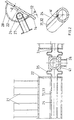
- FIG 1 is a section of the converter vessel 11, namely the Converter hat 12 including the end flange 15 shown with segments 13, which have meandering tubes 21.
- the tubes 21 open at the top a collector 23 and at the bottom in a collector 22.
- a collecting tube 24 is provided, in Figure 1b, this collecting tube 24 is outside the Collector 22 arranged and in Figure 1c, this manifold 24 is a half pipe the converter hat 12, located within the collector 22, attached.
- an outlet 27 is attached, which is blocked by shut-off elements 42 is lockable.
- the header pipe 24 provided in the collector 22 is between the segments Pipe pieces 34 connected.
- the one shown in FIG. 1b outside the outer wall 28 arranged collecting pipe 24 is connected to the collector 22 via connecting pipes 37 connected.
- FIGS. 1a and 1c show a section through the converter hat 12 with a tube 21, the collector 22 and the inner collecting tube 24.
- the collecting pipe 24 lies outside the collector 22, the collecting pipe 24 being connected to the collector 22 via connecting pipes 37.
- a cooling medium outlet 26 is connected to the collector 22.
- a drain 27 is provided on both the inside and outside manifolds 24 in FIGS.
- At least one openable vent (29) is provided in the header-side collector (23).
- the collecting pipe 24 is shown in detail, which is in the foot side Collector 22 with approximately the same distance to the wall 14 of the converter hat 12 and is spaced from the bottom of the outer wall 28 of the collector 22. On manifold 24 the drain 27 is connected.
- a section through the collector 22 is shown with a Collecting tube 24, which has openings 31, in the lower part of the picture in shape of holes 33 and in the middle of Figure 2 in the form of slots 32.
- the slots are arranged so that the flow of the cooling medium W on the way to Interior of the manifold 24 is resisted, here as opening wedge towards the inside of the pipe.
- the lower part of the image shows pipe sections 34 which extend over compensators 35 are connected to the collector 22. Furthermore, the pipe pieces 34 are through a Shut-off device 41 can be shut off, here in the form of a three-way valve which is connected to the Coolant outlet 26 is connected.
- Figure 3 shows the diagram of the segments 13 with the meandering tubes 21, the head end of the collector 23 and the base end of the collector 22 are connected.
- the collector 23 is connected to the cooling medium supply 25 and to the cooling medium outlet 26 connected and also connected to the manifold 24.
- the Collecting pipe 24 is connected to a water supply 36.
- the cooling medium supply 25 and the water supply 36 are via a changeover valve 51 switchable. Here, the direction of the cooling medium supply 25 and the Water supply 36 supplied flow direction reversed.
- This diagram also shows that the coolant supply 25 with a pump 45 for the main stream, that is about 90% of the amount of water Water supply 36 with a pump 46 for the secondary flow, that is about 10% of the Amount of water, and the cooling medium outlet 26 after its idle for ventilation of the other segments via the connector 43 is used.
Landscapes
- Engineering & Computer Science (AREA)
- Chemical & Material Sciences (AREA)
- Mechanical Engineering (AREA)
- Materials Engineering (AREA)
- Metallurgy (AREA)
- Organic Chemistry (AREA)
- Manufacturing & Machinery (AREA)
- General Engineering & Computer Science (AREA)
- Waste-Gas Treatment And Other Accessory Devices For Furnaces (AREA)
- Carbon Steel Or Casting Steel Manufacturing (AREA)
- Heat Treatment Of Strip Materials And Filament Materials (AREA)
- Furnace Details (AREA)
- Processing Of Solid Wastes (AREA)
Description
- Figur 1
- ein Schema der Hutkühlung
- Figur 2
- Detail der Sammelleitung und des Sammlers
- Figur 3
- Schaltbild der Entwässerung
In dem kopfseitigen Sammler (23) ist mindestens eine öffenbare Entlüftung (29) vorgesehen.
- 11
- Konvertergefäß
- 12
- Konverterhut
- 13
- Segment
- 14
- Wandung Hutsegment
- 15
- Flansch
- 21
- Rohr (mäanderförmig)
- 22
- Sammler fußseitig
- 23
- Sammler kopfseitig
- 24
- Sammlerrohr
- 25
- Kühlmedienzufuhr
- 26
- Kühlmedienablauf
- 27
- Ablaß
- 28
- Außenwand
- 29
- Entlüftung
- 31
- Öffnung
- 32
- Schlitz
- 33
- Bohrung
- 34
- Rohrstück
- 35
- Kompensator
- 36
- Wasserversorgung
- 37
- Verbindungsrohr
- 41,42
- Absperrorgan
- 43
- Verbindungsstück
- 44
- Auffangbehälter
- 45
- Pumpe Hauptzufuhr
- 46
- Pumpe Nebenzufuhr
- W
- Kühlmittel
- a
- Distanz
- 51
- Umschaltventil
Claims (14)
- Stahlwerkskonverter, an dessen Gefäßhut eine Hutkühlung vorgesehen ist, mit mäanderförmig angeordneten Leitungen (21) zur Führung des Kühlmediums, die im Fuß- und im Kopfbereich des Konverterhutes (12) in mindestens einem ringförmigen, rinnenartigen Sammler (22 bzw. 23) münden, und mit mindestens einem Zulauf (25) und einem Ablauf (26) für das Kühlmedium, wobei im Bereich des fußseitigen Sammlers (22) ein Sammelrohr (24 ) in Abstand von mindestens einer der Seitenwände des fußseitigen Sammlers (22) angeordnet ist, welches mindestens einen verschließbaren Ablaß (27) aufweist und mit dem fußseitigen Sammler (22) in der Weise in Verbindung steht, daß das in dem fußseitigen Sammler (22) befindliche Kühlmedium bei im Zulauf abgeschalteter Zufuhr des Kühlmediums rasch in das Sammelrohr (24) läuft.
- Stahlwerkskonverter nach Anspruch 1,
dadurch gekennzeichnet,daß das Sammelrohr (24) zu beiden Seiten und dem Grund des fußseitigen Sammlers (22) in etwa gleicher Distanz (a) beabstandet angeordnet ist, unddaß in der Wandung des Sammelrohres (24) Öffnungen (31) eingebracht sind, über die das Kühlmittel (W) vom fußseitigen Sammler (22) in das Rohrinnere des Sammelrohres (24) führbar ist. - Stahlwerkskonverter nach Anspruch 2,
dadurch gekennzeichnet,
daß die Öffnungen (31) als Schlitz (32) ausgestaltet sind. - Stahlwerkskonverter nach Anspruch 2,
dadurch gekennzeichnet,
daß die Öffnungen (31) Bohrungen (33) sind. - Stahlwerkskonverter nach den Ansprüchen 3 oder 4,
dadurch gekennzeichnet,
daß die Öffnungen (31) des Sammelrohres (24) eine das Einströmen des Kühlmediums (W) während des Betriebes behindernde Form aufweisen, z.B. eine konische Gestalt mit in Strömungsrichtung sich öffnenden Seitenwänden besitzen. - Stahlwerkskonverter nach einem der vorgenannten Ansprüche,
dadurch gekennzeichnet,
daß die gesamte Freifläche der Öffnungen (31) bis zum 5-fachen der Austrittsfläche des zugehörigen Kühlmedienablaufs (26) entspricht. - Stahlwerkskonverter nach einem der vorgenannten Ansprüche,
dadurch gekennzeichnet,
daß bei segmentförmiger Aufteilung der Konverterhutkühlung geschlossene Rohrstücke (34) vorgesehen sind, die die in den Segmenten (13) angeordneten mit Öffnungen (31) versehenen Sammelrohre (24) verbinden. - Stahlwerkskonverter nach Anspruch 7,
dadurch gekennzeichnet,
daß die einzelnen Rohrstücke (34) über Kompensatoren (35) mit der Wandung (14) der Konverterhutsegmente (13) verbunden sind. - Stahlwerkskonverter nach Anspruch 7,
dadurch gekennzeichnet,daß die Rohrstücke (34) als T-Stücke ausgestaltet sind unddaß je Ablaß (27) ein Absperrorgan (41) vorgesehen ist. - Stahlwerkskonverter nach Anspruch 1,
dadurch gekennzeichnet,
daß das Sammelrohr (24) zur Außenwand (28) des fußseitigen Sammlers (22) beabstandet ist und mit diesem über Verbindungsrohre (37) verbunden ist. - Stahiwerkskonverter nach Anspruch 10,
dadurch gekennzeichnet,daß das Sammelrohr (24) durch Absperrorgane (41, 42) absperrbar ist unddaß jeweils zwischen zwei Absperrorganen (41, 42) mindestens ein Kühimedienablauf (26) vorgesehen ist. - Stahlwerkskonverter nach Anspruch 11,
dadurch gekennzeichnet,
daß das Sammelrohr (24) an einer Wasserversorgung (36) angeschlossen ist, über die eine Teilmenge QT von QT = 5 bis 15 % x Q führbar ist, wobei Q die Gesamtmenge des dem Konverterhut (12) zugeführten Kühwassers ist. - Stahlwerkskonverter nach einem der vorgenannten Ansprüche,
dadurch gekennzeichnet,
daß in dem kopfseitigen Sammler (23) mindestens eine öffenbare Entlüftung (29) vorgesehen ist. - Stahlwerkskonverter nach einem der vorgenannten Ansprüche,
dadurch gekennzeichnet,
daß Umschaltventile (51) vorgesehen sind, mit denen die Kühtmedienzufuhr (25) und gegebenenfalls die Wasserversorgung (36) umschaltbar und der Kühlmedienablauf (26) abschaltbar ist.
Applications Claiming Priority (3)
| Application Number | Priority Date | Filing Date | Title |
|---|---|---|---|
| DE19730250 | 1997-07-08 | ||
| DE19730250A DE19730250C1 (de) | 1997-07-08 | 1997-07-08 | Stahlwerkskonverter mit Hutkühlung |
| PCT/DE1998/001634 WO1999002740A1 (de) | 1997-07-08 | 1998-06-15 | Stahlwerkskonverter mit hutkühlung |
Publications (2)
| Publication Number | Publication Date |
|---|---|
| EP0994972A1 EP0994972A1 (de) | 2000-04-26 |
| EP0994972B1 true EP0994972B1 (de) | 2001-08-16 |
Family
ID=7835742
Family Applications (1)
| Application Number | Title | Priority Date | Filing Date |
|---|---|---|---|
| EP98936179A Expired - Lifetime EP0994972B1 (de) | 1997-07-08 | 1998-06-15 | Stahlwerkskonverter mit hutkühlung |
Country Status (9)
| Country | Link |
|---|---|
| US (1) | US6277325B1 (de) |
| EP (1) | EP0994972B1 (de) |
| CN (1) | CN1082547C (de) |
| AT (1) | ATE204340T1 (de) |
| AU (1) | AU8532098A (de) |
| BR (1) | BR9810553A (de) |
| DE (2) | DE19730250C1 (de) |
| ES (1) | ES2159437T3 (de) |
| WO (1) | WO1999002740A1 (de) |
Families Citing this family (1)
| Publication number | Priority date | Publication date | Assignee | Title |
|---|---|---|---|---|
| US7452499B2 (en) * | 2004-10-29 | 2008-11-18 | Systems Spray-Cooled, Inc. | Furnace cooling system and method |
Family Cites Families (11)
| Publication number | Priority date | Publication date | Assignee | Title |
|---|---|---|---|---|
| US427841A (en) * | 1890-05-13 | John e | ||
| FR2144547B1 (de) * | 1971-07-05 | 1974-03-29 | Fives Lille Cail | |
| DE2151629A1 (de) * | 1971-10-16 | 1973-04-26 | Demag Ag | Kuehlvorrichtung fuer ein warmgaengiges gefaess, insbesondere fuer einen stahlwerkskonverter |
| AT338307B (de) * | 1973-07-23 | 1977-08-25 | Voest Ag | Metallurgisches gefass, insbesondere konverter |
| AT337741B (de) * | 1974-09-12 | 1977-07-11 | Voest Ag | Konverter mit einem konverterhut |
| US4128232A (en) * | 1977-06-30 | 1978-12-05 | Pennsylvania Engineering Corporation | Cooling assembly for metallurgical vessels |
| US4085924A (en) * | 1977-07-15 | 1978-04-25 | Pennsylvania Engineering Corporation | Cooling assembly for metallurgical vessels |
| AT357582B (de) * | 1978-04-04 | 1980-07-25 | Voest Alpine Ag | Kuehlsystem fuer ein metallurgisches gefaess |
| US4278241A (en) * | 1980-07-18 | 1981-07-14 | Chicago Bridge & Iron Company | Top cone cooling system for basic oxygen furnace |
| DE3048199C2 (de) * | 1980-12-20 | 1983-01-13 | Mannesmann AG, 4000 Düsseldorf | Metallurgisches Gefäß, insbesondere Stahlwerkskonverter |
| DE3330237C2 (de) * | 1983-08-22 | 1985-07-04 | Mannesmann AG, 4000 Düsseldorf | Metallurgisches Reaktionsgefäß, insbesondere Stahlwerkskonverter |
-
1997
- 1997-07-08 DE DE19730250A patent/DE19730250C1/de not_active Expired - Fee Related
-
1998
- 1998-06-15 AT AT98936179T patent/ATE204340T1/de active
- 1998-06-15 EP EP98936179A patent/EP0994972B1/de not_active Expired - Lifetime
- 1998-06-15 CN CN988070049A patent/CN1082547C/zh not_active Expired - Fee Related
- 1998-06-15 WO PCT/DE1998/001634 patent/WO1999002740A1/de not_active Ceased
- 1998-06-15 AU AU85320/98A patent/AU8532098A/en not_active Abandoned
- 1998-06-15 DE DE59801223T patent/DE59801223D1/de not_active Expired - Lifetime
- 1998-06-15 BR BR9810553-1A patent/BR9810553A/pt active Search and Examination
- 1998-06-15 US US09/462,668 patent/US6277325B1/en not_active Expired - Fee Related
- 1998-06-15 ES ES98936179T patent/ES2159437T3/es not_active Expired - Lifetime
Also Published As
| Publication number | Publication date |
|---|---|
| ATE204340T1 (de) | 2001-09-15 |
| EP0994972A1 (de) | 2000-04-26 |
| ES2159437T3 (es) | 2001-10-01 |
| AU8532098A (en) | 1999-02-08 |
| DE59801223D1 (de) | 2001-09-20 |
| WO1999002740A1 (de) | 1999-01-21 |
| BR9810553A (pt) | 2000-08-15 |
| CN1082547C (zh) | 2002-04-10 |
| US6277325B1 (en) | 2001-08-21 |
| DE19730250C1 (de) | 1998-08-06 |
| CN1262708A (zh) | 2000-08-09 |
Similar Documents
| Publication | Publication Date | Title |
|---|---|---|
| DE2135762A1 (de) | Fermentierungsverfahren sowie Vorrichtung zu dessen Durchführung | |
| DE19501547A1 (de) | Modularer Wärmeaustauscher | |
| DE102004040974A1 (de) | Gewickelter Wärmetauscher | |
| DE2517693C2 (de) | Als Längsgegenstromapparat ausgebildeter Wärmeaustauscher | |
| DE1461395A1 (de) | Steuereinrichtung fuer die Fluessigkeitsstroeme in einer Filteranlage | |
| DE3009850C2 (de) | Reaktorbehälter | |
| DE19730250C1 (de) | Stahlwerkskonverter mit Hutkühlung | |
| DE2316066C2 (de) | Kernreaktor, insbes. Druckwasserreaktor | |
| DE102008051819A1 (de) | Vorrichtung zur Verrohrung von Prozessanlagen der Nahrungsmittel- und Getränkeindustrie und Verfahren zum Betrieb einer Vorrichtung | |
| DE2003339B2 (de) | Vorrichtung zur speisung der blasoeffnungen im boden eines stahlkonverters | |
| EP2281132A1 (de) | Vorrichtung zur verrohrung von prozessanlagen der nahrungsmittel- und getränkeindustrie | |
| DE202019102229U1 (de) | Wärmeübertrageranordnung mit wenigstens einen Mehrpass-Wärmeübertrager | |
| DE1783165A1 (de) | Vorrichtung zur speisung der blasoeffnungen im boden eines konverters | |
| EP1126227A1 (de) | Dampfkondensator | |
| AT391877B (de) | Metallurgisches gefaess, insbesondere stationaerer oder auswechselbarer stahlwerkskonverter | |
| EP0760395A1 (de) | Vorrichtung zum Flüssigmetall-Transport in der Giesshalle eines Schachtofens und Verfahren zum Betrieb dieser Vorrichtung | |
| EP1742006A1 (de) | Verfahren und Anordnung zur Strömungsführung in Rohrbündel-Wärmeaustauschern zur thermischen Behandlung von Suspensionen | |
| DE4221130C2 (de) | Wasserrohr-Dampferzeuger mit vertikal angeordneten Fieldrohren | |
| EP0104326A2 (de) | Zweikreislanze zum frischen von metallschmelzen | |
| DE29823740U1 (de) | Vorrichtung zur vertikalen Temperaturschichtung eines Fluids in einem Speicherbehälter | |
| DE2323378A1 (de) | Notkuehlsystem fuer einen kernreaktor | |
| DE2751942C2 (de) | Gaserzeuger mit Schlackenaustrag in eine Löschkammer | |
| DE2917755A1 (de) | Wassergekuehlter deckel fuer industrieoefen | |
| DE2030944A1 (de) | Tiegel oder Konverter, der eine Wasserkühlung des Blechmantels auf weist | |
| DE102005031660A1 (de) | Schüttgut-Temperier-Anlage |
Legal Events
| Date | Code | Title | Description |
|---|---|---|---|
| PUAI | Public reference made under article 153(3) epc to a published international application that has entered the european phase |
Free format text: ORIGINAL CODE: 0009012 |
|
| 17P | Request for examination filed |
Effective date: 20000106 |
|
| AK | Designated contracting states |
Kind code of ref document: A1 Designated state(s): AT DE ES FR GB IT |
|
| GRAG | Despatch of communication of intention to grant |
Free format text: ORIGINAL CODE: EPIDOS AGRA |
|
| GRAG | Despatch of communication of intention to grant |
Free format text: ORIGINAL CODE: EPIDOS AGRA |
|
| GRAH | Despatch of communication of intention to grant a patent |
Free format text: ORIGINAL CODE: EPIDOS IGRA |
|
| 17Q | First examination report despatched |
Effective date: 20010110 |
|
| GRAH | Despatch of communication of intention to grant a patent |
Free format text: ORIGINAL CODE: EPIDOS IGRA |
|
| GRAA | (expected) grant |
Free format text: ORIGINAL CODE: 0009210 |
|
| AK | Designated contracting states |
Kind code of ref document: B1 Designated state(s): AT DE ES FR GB IT |
|
| REF | Corresponds to: |
Ref document number: 204340 Country of ref document: AT Date of ref document: 20010915 Kind code of ref document: T |
|
| GBT | Gb: translation of ep patent filed (gb section 77(6)(a)/1977) |
Effective date: 20010816 |
|
| REF | Corresponds to: |
Ref document number: 59801223 Country of ref document: DE Date of ref document: 20010920 |
|
| REG | Reference to a national code |
Ref country code: ES Ref legal event code: FG2A Ref document number: 2159437 Country of ref document: ES Kind code of ref document: T3 |
|
| REG | Reference to a national code |
Ref country code: GB Ref legal event code: IF02 |
|
| ET | Fr: translation filed | ||
| PGFP | Annual fee paid to national office [announced via postgrant information from national office to epo] |
Ref country code: FR Payment date: 20020611 Year of fee payment: 5 |
|
| PGFP | Annual fee paid to national office [announced via postgrant information from national office to epo] |
Ref country code: ES Payment date: 20020613 Year of fee payment: 5 |
|
| PLBE | No opposition filed within time limit |
Free format text: ORIGINAL CODE: 0009261 |
|
| STAA | Information on the status of an ep patent application or granted ep patent |
Free format text: STATUS: NO OPPOSITION FILED WITHIN TIME LIMIT |
|
| 26N | No opposition filed | ||
| PG25 | Lapsed in a contracting state [announced via postgrant information from national office to epo] |
Ref country code: ES Free format text: LAPSE BECAUSE OF NON-PAYMENT OF DUE FEES Effective date: 20030616 |
|
| PG25 | Lapsed in a contracting state [announced via postgrant information from national office to epo] |
Ref country code: FR Free format text: LAPSE BECAUSE OF NON-PAYMENT OF DUE FEES Effective date: 20040227 |
|
| REG | Reference to a national code |
Ref country code: FR Ref legal event code: ST |
|
| REG | Reference to a national code |
Ref country code: ES Ref legal event code: FD2A Effective date: 20030616 |
|
| REG | Reference to a national code |
Ref country code: DE Ref legal event code: R082 Ref document number: 59801223 Country of ref document: DE Representative=s name: ANWALTSKANZLEI MEISSNER & MEISSNER, DE Ref country code: DE Ref legal event code: R081 Ref document number: 59801223 Country of ref document: DE Owner name: SMS GROUP GMBH, DE Free format text: FORMER OWNER: SMS SIEMAG AKTIENGESELLSCHAFT, 40237 DUESSELDORF, DE |
|
| PGFP | Annual fee paid to national office [announced via postgrant information from national office to epo] |
Ref country code: DE Payment date: 20170621 Year of fee payment: 20 Ref country code: GB Payment date: 20170620 Year of fee payment: 20 |
|
| PGFP | Annual fee paid to national office [announced via postgrant information from national office to epo] |
Ref country code: IT Payment date: 20170622 Year of fee payment: 20 Ref country code: AT Payment date: 20170622 Year of fee payment: 20 |
|
| REG | Reference to a national code |
Ref country code: DE Ref legal event code: R071 Ref document number: 59801223 Country of ref document: DE |
|
| REG | Reference to a national code |
Ref country code: GB Ref legal event code: PE20 Expiry date: 20180614 |
|
| PG25 | Lapsed in a contracting state [announced via postgrant information from national office to epo] |
Ref country code: GB Free format text: LAPSE BECAUSE OF EXPIRATION OF PROTECTION Effective date: 20180614 |
|
| REG | Reference to a national code |
Ref country code: AT Ref legal event code: MK07 Ref document number: 204340 Country of ref document: AT Kind code of ref document: T Effective date: 20180615 |