EP0994811B1 - Fermeture de conteneur contenant un cadeau publicitaire - Google Patents
Fermeture de conteneur contenant un cadeau publicitaire Download PDFInfo
- Publication number
- EP0994811B1 EP0994811B1 EP98934271A EP98934271A EP0994811B1 EP 0994811 B1 EP0994811 B1 EP 0994811B1 EP 98934271 A EP98934271 A EP 98934271A EP 98934271 A EP98934271 A EP 98934271A EP 0994811 B1 EP0994811 B1 EP 0994811B1
- Authority
- EP
- European Patent Office
- Prior art keywords
- compartment
- closure
- side wall
- flange
- container
- Prior art date
- Legal status (The legal status is an assumption and is not a legal conclusion. Google has not performed a legal analysis and makes no representation as to the accuracy of the status listed.)
- Expired - Lifetime
Links
Images


Classifications
-
- B—PERFORMING OPERATIONS; TRANSPORTING
- B65—CONVEYING; PACKING; STORING; HANDLING THIN OR FILAMENTARY MATERIAL
- B65D—CONTAINERS FOR STORAGE OR TRANSPORT OF ARTICLES OR MATERIALS, e.g. BAGS, BARRELS, BOTTLES, BOXES, CANS, CARTONS, CRATES, DRUMS, JARS, TANKS, HOPPERS, FORWARDING CONTAINERS; ACCESSORIES, CLOSURES, OR FITTINGS THEREFOR; PACKAGING ELEMENTS; PACKAGES
- B65D51/00—Closures not otherwise provided for
- B65D51/24—Closures not otherwise provided for combined or co-operating with auxiliary devices for non-closing purposes
- B65D51/28—Closures not otherwise provided for combined or co-operating with auxiliary devices for non-closing purposes with auxiliary containers for additional articles or materials
Definitions
- the present invention relates generally to promotional closures for containers configured for use in connection with a sales promotion or game, and more particularly to a promotion-receiving compartment for a closure which is configured to facilitate easy-opening by consumers for removal of a promotional element from within the compartment.
- Promotions and games which are associated with the sale of products have shown enduring popularity with consumers.
- a wide variety of such promotions and games are known, and may include gaming systems where game elements are collected to receive an award, or receipt by a consumer of a promotional element which can be redeemed for an award, or which may have intrinsic value for the consumer.
- Promotional systems for use with container closures have heretofore taken various forms. For example, it has been known to provide the liner portion of a closure in the form of a gaming piece, whereby collection of certain ones of the liners permits prize redemption, or the liners themselves can be individually redeemed for cash or other awards. It has also been known to provide container closures with a compartment element positionable generally within the closure so that a promotional element can be positioned within the compartment for removal upon opening of the container. Closure/compartment arrangements of this nature are disclosed in U.S. Patent No. 5,056,659, to Howes et al. The preamble of claim 1 is based on this prior art.
- the present invention is directed to an easy-open promotion-receiving member for a promotional closure which is configured to facilitate convenient manipulation and opening by consumers for use in a promotional or gaming system.
- a closure for a container including a cap having a top wall and a depending skirt, a compartment having a bottom wall and a surrounding side wall extending therefrom defining a circumference, said compartment arranged to be held within said cap and removable therefrom, characterized by said side wall having a circumferentially arranged frangible portion extending at least partially about the circumference of said side wall, said frangible portion being at least partially separable from remaining portions of said side wall to open said compartment.
- a method of accessing a prize from a bottle including the steps of removing a closure from the bottle, removing a prize-containing compartment having a bottom wall and a surrounding side wall from within said closure, accessing said prize from within said compartment by tearing open said compartment by at least partially separating a frangible portion of said compartment which extends at least partially circumferentially of the side wall of said compartment, and removing said prize from within said compartment.
- the promotion compartment of the present invention is positionable beneath the top wall portion of the outer closure cap, and inwardly of the annular skirt portion of the cap for disposition generally within an associated container.
- the cup-shaped promotion compartment includes a circular bottom wall, and an upstanding, generally cylindrical side wall extending upwardly therefrom.
- the compartment includes a annular flange extending outwardly from the side wall.
- the cap includes a seal covering an inside of the top wall thereof and having an annular radially inwardly extending flange or lip. The annular flange of the compartment is captured between the top wall and the lip to be held within the cap. When the cap is removed from the bottle, the compartment can be removed from the cap by manipulating the compartment to cause the flange to disengage from the lip.
- the side wall of the compartment comprises a frangible portion which can be opened after the closure is removed from the associated container and the promotion compartment is removed from within the closure cap. Opening of the frangible portion of the compartment facilitates removal of a promotional element, such as a coupon, currency, or other promotional item, from within the promotion compartment.
- the frangible portion of the side wall comprises a side wall with a circumferentially extending band which extends at least partially about the circumference of the side wall and is defined by tear lines of weakened side wall, e.g., molded relatively thin wall sections, score lines, perforations, etc. Fracture along the weakened lines permits opening of the compartment such as by a hinging movement of the circular bottom wall about a remaining side wall portion which joins the bottom wall to the remainder of the compartment.
- the annular flange acts in the nature of a finger grip to facilitate opening of the compartment.
- a bottom flange is also included which provides a finger grip for removing the compartment from the cap and for manipulating the compartment during opening thereof.
- the bottom flange also protects the pull tab affixed to the frangible portion during handling, assembly, and high speed application of closures to containers.
- the promotion compartment is thus split or opened circumferentially from its cup-shaped configuration, facilitating convenient access to a promotional element carried within the compartment.
- a preferred fabrication of the compartment from low density polyethylene further facilitates convenient opening of the compartment.
- the promotional closure embodying the principles of the present invention thus provides a method for accessing a prize or like promotional piece from a bottle.
- the method comprises the steps of removing a closure from the associated bottle, and thereafter removing a prize-container compartment from within the closure.
- the prize is accessed from within the compartment by tearing open the compartment by at least partially separating a frangible portion of the compartment, which extends at least partially circumferentially of the compartment. By this opening of the compartment, the prize can thereafter be accessed by removing the prize from within the compartment.
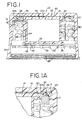
- FIGURE 1 therein is illustrated a promotional closure 10 including a easy-open promotion-receiving member embodying the principles of the present invention.
- Promotional closure 10 is particularly configured for use with an associated container, a portion of which is illustrated and is designated C shown in FIGURE 1 a.
- the container such as a bottle, can be closed by the closure such as by threaded application to a neck portion of the container.
- Closures of the type illustrated in FIGURE 1 can be formed in accordance with the teachings of U.S. Patent No. 4,497,765.
- Closure 10 is in the form of an assembly that includes a molded plastic outer closure cap 12 having a circular top wall portion 14 and a depending annular skirt portion 16.
- the annular skirt portion 16 includes an internal helical thread formation 18 configured for cooperating threaded engagement with the associated container C.
- a sealing liner 20 positioned adjacent the top wall portion 14 of the closure facilitates sealing engagement of the closure with an associated container, and permits the closure to be configured for use with containers having carbonated contents.
- the illustrated closure 10 is of the so-called tamper-indicating type, and includes a detachable pilfer bad 22 depending from the annular skirt portion 16.
- the pilfer band 22 is distinguished from the upper closure cap 12 by a circumferentially extending score line 24, with a plurality of circumferentially spaced frangible ribs 26 extending between the inside surfaces of the closure cap and the pilfer band.
- a plurality of circumferentially spaced container-engaging flexible projections 28 extend inwardly of the pilfer band, for cooperating engagement with the locking portion of the associated container.
- the frangible ribs 26 split and fracture during removal of the closure from the container, thereby separating the pilfer band from the skirt portion 16 of the closure cap for the desired tamper-evidence.
- the illustrated embodiment of the pilfer band is configured in accordance with U.S. Patent No. 4,938,370, but may alternately be configured in accordance with the teachings of U.S. Patent No. 4,418,828.
- the closure 10 is intended for use in connection with consumer promotions or games, and to this end, the closure includes a promotion-receiving member positioned generally within the closure cap 12.
- the promotion-receiving member is provided in the form of a promotion compartment 30 having a generally cup-shaped configuration including a circular bottom wall 32, and a generally cylindrical upstanding side wall 34 extending upwardly from the bottom wall 32.
- the promotion compartment 30 includes a depending annular bottom flange 36 which facilitates finger grasping for removal of the compartment from within the closure cap 12.
- the bottom flange 36 also desirably protects the pull tab (as will be described) of the compartment 30.
- the compartment 30 is preferably of unitary construction apart from its cover member, and preferably molded from low density polyethylene plastic material which, as will be further described, facilitates tearing, opening, or splitting of the compartment so that a promotional element positioned within the compartment can be easily removed by consumers.
- Positioning of the compartment 30 within the closure cap 12 is facilitated by the provision of a annular compartment flange 38 which extends generally outwardly from the upper edge of the side wall 34.
- the annular compartment flange 38 is interengaged with a portion of the sealing liner 20 of closure 10, by the provision of a annular liner flange or lip 39 on the liner which fits between the container C and the compartment flange 38.
- the flange 39 extends from an annular liner bead 20b.
- the compartment flange 38 is preferably held in generally captive relationship between the liner flange 39 and the liner bead 20b within closure cap 12.
- a closure prize compartment embodying the principles of the present invention can be otherwise retained within the associated outer closure cap.
- the closure assembly can be configured such that the upper annular flange 38 of the compartment effects sealing engagement with the associated container, with the closure liner 20 having no lip 39 or the like.
- a preformed disc liner can be provided in the outer cap (rather than the illustrated molded in place liner 20) to provide a so-called secondary seal, that is, an arrangement for sealing the container after removal of the compartment 30 from within the outer cap.
- the compartment may be configured for self-venting. Such venting can be desirable in view of the elevated gas pressure which can exist within the compartment from use of the closure assembly on a container having carbonated contents.
- a self-venting compartment can be provided by configuring the seal of cover member 40 to delaminate or open in a predetermined fashion.
- a suitable self-venting seal arrangement is described in commonly assigned U.S. Patent Application Serial No. 08/746,710, filed November 15, 1996.
- the installation of the compartment 30 into the cap 12 includes the bending of the compartment flange 38 upwardly into a cone shape for passing an outer edge of the compartment flange between the lip 39 and the liner bead 20b.
- the bending is done by a tool which then releases the compartment flange 38 allowing the compartment flange to snap back to its planar configuration fully inserted between the lip 39 ad the bead 20b.
- FIGURE 1 also illustrates that in the preferred form, the tab 48 extends radially outwardly no further than the bottom flange 36, and the top flange 38. This protects the tab 48 from damage during handling and assembly, and facilitates highspeed application of closures to containers.
- a suitable promotional element can be positioned within the interior of the compartment 30.
- a promotional element can be provided in the form of a coupon redeemable for an award or the like, folded currency (i.e., cash), or some other suitable promotional article.
- Retention of the promotional element within the compartment is desirably enhanced by the optional provision of a cover member 40 in the form of a membrane fitted to the flange 38, which cover member 40 can be provided in the form of a suitable plastic film or the like heat-sealed or otherwise secured to the flange 38 of the compartment.
- the cover 40 acts to desirably isolate the contents of the compartment from the contents of the associated container C, and to desirably enhance the structural integrity of the compartment 30 without impairing easy-opening of the compartment.
- the cover member can be a laminate of low density polyethylene with PET (polyethylene terephthalate) with a polyurethane bonding agent.
- a substantially rigid reinforcing disc 41 is carried in a recessed annular step 42 (see FIGURE 1) of the flange 38 and is sealed to the cover member 40.
- the disc 41 is sufficiently thick to substantially prevent "doming” which prevents pressing of a top of the cover member 40 to the inside surface 20a.
- the disc 41 is preferably composed of high density polyethylene. As an alternative arrangement the disc 41 can have a snap engagement to positively lock to the annular step 42. The disc can also be provided with a vent hole beneath the cover member for venting if the cover member is peeled off, or if a removable membrane-like cover member is contemplated.
- One size of closure commonly used for containers for carbonated beverages has a diameter of 28 millimeters, with a promotion compartment embodying the principles of the present invention sized for disposition within an associated container when a closure of this size is applied thereto. While a promotion compartment in accordance with this invention can be configured for use with closures of many different sizes, use in connection with a 28 millimeter closure necessarily requires that the promotion compartment be relatively small in size. As such, removal of a promotional element from within the compartment should be as easy as possible to permit removal by consumers without resort to use of a tool or other implement.
- the promotion compartment 30 in accordance with the present invention is configured for easy-opening, that is, is configured to split or open in a fashion which permits the contents of the compartment to be easily removed without the use of an associated implement.
- the promotion compartment 30 is sized for use with 28 millimeter closures, consumers can very easily gain access to the contents of the compartment.
- the sidewall has an upper annular L-shaped (in cross-section) rim 44 which provides the stepped recess 42 for holding the disc 41.
- the depending annular bottom flange 36 is also L-shaped in cross-section, forming a bottom recess 45.
- the flange 36 can be used for finger gripping to remove the compartment from the cap.
- an outer surface 32a of the bottom wall 32 is exposed.
- the outer surface 32a can carry indicia such as advertising, game information, or an announcement of a winning compartment, i.e., that the compartment contains a prize.
- a handle or tab 46 is provided having an elongate body 48 with finger-gripping ribs 50 provided thereon on a front side and ribs 52 optionally provided on a back side.
- the elongate body 48 is connected to a pull portion 54 which is molded to a side wall region 58 having a reduced thickness.
- the pull portion 54 has a height in a direction parallel to an axis of the cylindrical wall 34.
- Two sets of intermittently weakened lines, preferably formed by molding relatively thin regions in the sidewall 34, are arranged in parallel around a partial circumference of the wall 34, spaced apart a distance approximating the height of the pull portion.
- the circumferentially extending tear lines preferably extend 270°-300° around the circumference, in substantially parallel relationship to each other.
- a top weakened or tear line 60 has intermittent bridges or residual regions 62.
- a lower weakened or tear line 64 has residual regions 66.
- the upper and lower tear lines 60, 64 are spaced apart to define a frangible band-shaped portion 68 therebetween extending from the pull portion 54 around a partial circumference of the wall 34.
- the upper tear line 60 terminates in a first substantially circular recess 70 while the lower tear line 64 terminates in a second substantially circular recess 72.
- a last region 74 of the tear line 60 which is contiguous with the recess 70, has a depth decreasing into the recess 70.
- a last region 76 of the tear line 64 contiguous with the second recess 72 has a depth decreasing into the circular recess 72. The decreasing depth of the tear lines and the circular recesses tend to slow down and terminate ripping of the side wall at the recesses.
- the first circular recess 70 terminates around the circumference of the wall 34 at a position A, while the second circular recess 72 extends further and terminates at the position B.
- the difference C between these two positions tends to cause the frangible portion 68, if ripped past the recesses 70, 72, to be removed along offset paths 80, 82 shown dashed, which are offset at an end region thereof toward the rim 44 rather than to continue across the side wall circumferentially.
- the frangible portion 68 is forcibly removed, a region 90 substantially remains intact to retain the flange 38 connected to the wall 34 at this position.
- the residuals 62, 66 can be formed by relatively thick regions of the thinly molded tear lines 60, 64 or by using overlying bridge pieces similar to the bridge pieces 26 spanning across the score line 24 of the pilfer band.
- FIGURE 5 illustrates the promotion compartment 30 removed from the cap and in a partial stage of opening.
- the tab or handle 46 has been pulled from the region of reduced thickness 58 along a tear line 92 and the tear lines 60, 64.
- the residuals 62, 66 have been broken into half pieces or fragmentary pieces 62a, 62b and 66a, 66b.
- the frangible portion or band 68 is sufficiently opened, the promotion piece held within the container 30 can be removed. If the frangible band-shaped portion 68 is continuously torn from the wall 34, the offset terminations A and B will cause an angular rip toward the flange 38 preventing a complete circumferential rip of the band and separation of the compartment 30 into top and bottom pieces. It is preferable to retain the entire opened compartment 30 as a single piece, or to allow only the band 68 to be removed while retaining the remainder of the container 30 as a single piece.
- FIGURES 6 and 7 illustrates a alternate embodiment promotion-receiving compartment 100 having a wide band 102 across its side wall 106 defined by two continuous tear lines 108, 110.
- a tangentially extending handle 116 connects to the band 102 at a rectangular depression 118 which form a reduced thickness wall region.
- the vertical line 120 at the inner face between the handle 116 ad the recess 118 separates and the band 102 can be peeled open along the tear lines 108, 110 circumferentially around the wall 106 to terminations A, B shown in FIGURE 7.
- no circular enlarged recesses are used at the termination positions A, B, and the termination positions are not offset circumferentially.
- the depth of the tear lines 108, 110 decreases gradually throughout the regions 126, 128 which are adjacent the terminal positions A, B. This decrease in depth at the terminal regions effectively slows the speed of peeling or tearing of the panel 102 from the wall 106 to prevent unwanted tearing throughout the wall region 130 between the terminal positions A, B and the recess 118.
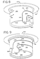
- FIGURE 8 illustrates a further alternate promotion-receiving compartment 200.
- stepped annular top and bottom flanges as in the previous embodiments, are not used but optionally could be used. Instead, a reinforced planar annular flange 201 and a recessed bottom 202 are used.
- a frangible portion in the form of a band 204 is formed by a first tear line 206 and a second tear line 208 formed into an annular side wall 210 of the container 200.
- the tear lines 206, 208 extend substantially circumferentially around a portion of the circumference of the side wall 210 and turn down arcuately at positions 212, 214 into axially arranged tear line portions 216, 218 which extend to a bottom edge 220 of the wall 210. Additionally, an overhang portion 224 is provided contiguous with the band 204 and which extends outwardly of the edge 220 to provide a finger grip or pull tab.
- the tear lines 206, 208 wrap around the circumference of the wall 210 and terminate at positions A, B which can, for example, be configured and shaped as positions A, B shown in FIGURE 7 with decreasing depth contiguous to the positions A, B; or configured and shaped as the terminations A, B shown in FIGURE 3 with offset circular recesses and decreasing depth. Although no residuals are shown in the tear lines 206, 208 in the embodiment of FIGURE 8, it is also possible to use residuals to strengthen the container.
- FIGURE 9 shows a still further alternate embodiment promotion-receiving compartment 300, somewhat similar to the compartment shown in FIGURE 8.
- a frangible portion comprising band 304 defined by a first tear line 306 and a tear line 308 formed into an annular wall 310 of the container, extends circumferentially around the annular wall 310.
- the tear lines are arcuately turned down toward a bottom edge 320 of the wall 310.
- a recessed bottom wall 346 is provided.
- the tear lines 306, 308 extend downwardly into expanded tear lines 322, 324 diverging from each other. The tear lines 322, 324 then are turned downwardly into tear lines 326, 328 to the bottom edge 320 of the wall 310.
- the band 304 extends further outwardly of the bottom edge 320 with an overhanging portion 330.
- the overhanging portion 330 as well as the tear lines 322, 324, 326, 328 define a pull tab, easily gripped and manipulated for removing the band along the tear lines 326, 328, 322, 324, 306 and 304 around the partial circumference of the wall 310.
- the tear lines 306, 308 terminate at positions A, B, (not shown) in a fashion such as that shown in FIGURE 3 or FIGURE 7, or combination of the two methods.
- residuals can be used optionally to increase the strength of the container 300, spaced intermittently along the tear lines.
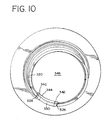
- FIGURE 10 illustrates in a bottom view the tab 330 having on a back side thereof reinforcing gussets 340, 342, which are molded into a recess region 344 of the bottom wall 346.
Landscapes
- Engineering & Computer Science (AREA)
- Mechanical Engineering (AREA)
- Closures For Containers (AREA)
- Packages (AREA)
Claims (32)
- Bouchon (10) de récipient, comprenant :un capuchon (12) ayant une paroi supérieure (14) et une jupe descendante (16),un compartiment (30) ayant une paroi inférieure (32) et une paroi latérale périphérique (34) qui s'étend de la paroi de fond et délimitant une circonférence, le compartiment (30) étant destiné à être retenu dans le capuchon (12) et à en être retiré, caractérisé en ce quela paroi latérale (34) a une partie cassable (68) disposée circonférentiellement et s'étendant au moins en partie autour de la circonférence de la paroi latérale (34), la partie cassable (68) étant séparable au moins partiellement des parties restantes de la paroi latérale (34) afin que le compartiment (30) soit ouvert.
- Bouchon (10) selon la revendication 1, caractérisé en ce que le compartiment (30) a un flasque supérieur (38) qui s'étend radialement vers l'extérieur de la paroi latérale (34), et
le capuchon (12) comporte une partie annulaire d'étanchéité (20) disposée contre la paroi supérieure (14), le flasque supérieur (38) étant disposé afin qu'il soit capturé contre la partie annulaire d'étanchéité (20) par le compartiment (30) lorsque le capuchon (12) est installé sur le récipient. - Bouchon (10) selon la revendication 2, caractérisé en ce que la partie annulaire d'étanchéité (20) comporte une lèvre (39) qui s'étend radialement vers l'intérieur, et le flasque supérieur (38) est capturé entre la lèvre (39) et la paroi supérieure (14).
- Bouchon (10) selon la revendication 1, caractérisé en ce que la partie cassable (68) comprend une partie en forme de bande qui s'étend circonférentiellement et appartenant à la paroi latérale délimitée par une ligne supérieure (60) de déchirure qui s'étend circonférentiellement et une ligne inférieure (66) de déchirure qui s'étend circonférentiellement, et une partie (46) de patte qui peut être saisie par un doigt et qui s'étend depuis une extrémité de la partie en forme de bande.
- Bouchon (10) selon la revendication 4, caractérisé en ce que la partie de patte (46) s'étend radialement vers l'extérieur depuis la partie en forme de bande.
- Bouchon (10) selon la revendication 4, caractérisé en ce que la partie de patte (46) s'étend tangentiellement depuis la partie en forme de bande.
- Bouchon (10) selon la revendication 4, caractérisé en ce que la partie de patte (46) s'étend axialement depuis la partie en forme de bande.
- Bouchon (10) selon la revendication 4, caractérisé en ce que la première ligne de déchirure (60) s'étend depuis ladite extrémité de la partie en forme de bande en direction circonférentielle vers une première partie terminale (70) et la seconde ligne de déchirure (66) s'étend circonférentiellement vers une seconde position terminale (72) qui est plus éloignée autour de la circonférence que la première position terminale.
- Bouchon (10) selon la revendication 4, caractérisé en ce que les première et seconde lignes de déchirure (60, 66) se terminent par des cavités circulaires élargies.
- Bouchon (10) selon la revendication 4, caractérisé en ce que les première et seconde lignes de déchirure (60, 66) sont discontinues sur leur longueur et forment des régions distantes de renforcement.
- Bouchon (10) selon la revendication 4, caractérisé en ce que les première et seconde lignes de déchirure (60, 66) ont chacune une première profondeur dans la paroi latérale dans une première partie des longueurs circonférentielles (62, 64) des première et seconde lignes de déchirure (60, 66), et une profondeur réduite dans des régions terminales adjacentes à une seconde partie (74, 76) de leur longueur circonférentielle.
- Bouchon (10) selon la revendication 1, caractérisé en ce que le compartiment comprend en outre un organe de couvercle (40) disposé afin qu'il recouvre une extrémité supérieure du récipient pour fermer le récipient de manière étanche.
- Bouchon (10) selon la revendication 12, caractérisé en ce que ledit compartiment (30) comporte en outre un disque de renforcement (91) supporté sur le récipient et recouvrant l'extrémité supérieure.
- Bouchon (10) selon la revendication 13, caractérisé en ce que le compartiment (30) comporte un flasque annulaire supérieur (38) qui s'étend radialement vers l'extérieur de l'extrémité supérieure et le disque de renforcement (41) est supporté sur le flasque (38), et l'organe de couvercle (40) est scellé au flasque (38) en recouvrant le disque de renforcement (41).
- Bouchon (10) selon la revendication 1, caractérisé en ce que le compartiment (30) comporte en outre un flasque supérieur (38) qui s'étend radialement depuis une extrémité supérieure de la paroi latérale (34), et un flasque inférieur (36) qui s'étend vers le bas de la paroi inférieure, le flasque supérieur (38) étant disposé afin qu'il soit capturé entre le capuchon (12) et le récipient lorsque le capuchon (12) est installé sur le récipient.
- Bouchon (10) selon la revendication 1, caractérisé en ce que le compartiment (30) comporte une patte (46) qui peut être saisie et qui s'étend depuis un bord terminal initial (58) de la partie cassable (68), et la paroi latérale possède une région disposée axialement avec une épaisseur réduite sur une largeur de la partie cassable au bord terminal initial (58) de la partie cassable.
- Bouchon (10) selon la revendication 16, caractérisé en ce que le compartiment (30) comporte un flasque inférieur (36) qui s'étend vers l'extérieur de la paroi latérale (34), et la patte (46) qui peut être saisie dépasse radialement de la paroi latérale (34) mais pas au-delà du flasque inférieur (36).
- Bouchon (10) selon la revendication 1, caractérisé en ce quela paroi latérale (34) délimite une extrémité supérieure ouverte, et comprenant en outreun disque pratiquement rigide (40) supporté sur la paroi latérale (39) et recouvrant pratiquement l'extrémité supérieure ouverte.
- Bouchon (10) selon la revendication 18, caractérisé en ce que le compartiment (30) comporte en outre un flasque annulaire (38) qui entoure l'extrémité supérieure ouverte, et le disque (40) est supporté sur le flasque annulaire (38).
- Bouchon (10) selon la revendication 19, caractérisé en ce que le flasque annulaire (38) comprend une cavité annulaire (42) à gradin destinée à maintenir le disque (40).
- Bouchon (10) selon la revendication 19, caractérisé en ce que le capuchon (12) comporte une lèvre annulaire (39) adjacente à la paroi supérieure (14) et s'étendant radialement vers l'intérieur, et en ce que le flasque annulaire (38) est capturé entre la paroi supérieure (14) et la lèvre (39) afin que le compartiment (30) soit retenu dans le capuchon (12).
- Bouchon (10) selon la revendication 19, comprenant en outre un film de scellement (41) qui est scellé sur le flasque annulaire (38).
- Bouchon (10) selon la revendication 22, caractérisé en ce que la paroi latérale (34) comporte une bande (68) qui peut être retirée par cassure et qui s'étend autour d'une partie importante de la circonférence de la paroi latérale (34).
- Bouchon (10) selon la revendication 1, caractérisé en ce quele capuchon (12) comprend un organe à filet interne conformé destiné à coopérer par vissage avec le récipient, et en ce quele compartiment (30) peut être disposé de façon générale à l'intérieur du capuchon (12) du bouchon, le compartiment ayant une paroi inférieure circulaire (32), une paroi latérale (34) de forme générale cylindrique qui remonte et s'étend depuis la paroi de fond pour délimiter une circonférence, un flasque annulaire supérieur (38) qui s'étend vers l'extérieur de la paroi latérale (34), le compartiment (30) ayant une configuration permettant la disposition dans le capuchon (12) du bouchon afin que le flasque supérieur (38) soit disposé de façon générale entre la paroi supérieure (14) du capuchon (12) du bouchon et le récipient, le compartiment (30) pouvant être retiré de l'intérieur du capuchon (12) du bouchon après enlèvement de l'ensemble (10) à bouchon du récipient,le compartiment (30) comprenant une partie cassable (68) destinée à ouvrir le compartiment (30) et comprenant une partie en forme de bande disposée dans la paroi latérale (34) délimitée par une paire de lignes espacées de déchirure (60, 66) qui s'étendent circonférentiellement et sont disposées au moins partiellement autour de la circonférence de la paroi latérale (34), la partie cassable (68) ayant une patte (46) à tirer raccordée à la partie en forme de bande pour assurer la déchirure de la partie en forme de bande le long des lignes de déchirure (60, 66).
- Ensemble à bouchon (10) selon la revendication 24, caractérisé en ce que le compartiment (30) comprend un dispositif à couvercle (40) disposé près du flasque annulaire supérieur (38) afin qu'il ferme l'intérieur du compartiment (30).
- Ensemble à bouchon (10) selon la revendication 25, caractérisé en ce que le dispositif à couvercle (40) comporte un organe de couvercle (41) en forme de membrane scellé sur le flasque annulaire (38).
- Ensemble à bouchon (10) selon la revendication 25, caractérisé en ce que le dispositif à couvercle (40) comporte un disque circulaire.
- Ensemble à bouchon (10) selon la revendication 24, caractérisé en ce que la patte à tirer (46) est disposée radialement à l'extérieur de la paroi latérale (34) du compartiment (30).
- Ensemble à bouchon (10) selon la revendication 24, caractérisé en ce que la patte à tirer (46) s'étend vers le bas depuis la partie en forme de bande.
- Ensemble à bouchon (10) selon la revendication 24, caractérisé en ce que le compartiment (30) comprend un flasque inférieur (36) qui descend depuis la paroi circulaire de fond (32).
- Ensemble à bouchon (10) selon la revendication 24, caractérisé en ce que les lignes de déchirure (60, 66) sont délimitées par des régions relativement minces affaiblies de manière intermittente et appartenant à la paroi latérale.
- Procédé d'accès à un lot depuis une bouteille, comprenant les étapes suivantes :l'enlèvement d'un bouchon (10) de la bouteille,l'enlèvement d'un compartiment destiné à contenir un lot (30) ayant une paroi inférieure (32) et une paroi latérale périphérique (34) de l'intérieur du bouchon, avec accès au lot depuis l'intérieur du compartiment par ouverture par déchirure du compartiment par séparation au moins partielle d'une partie cassable (68) du compartiment qui s'étend au moins partiellement en direction circonférentielle de la paroi latérale du compartiment, etl'enlèvement du lot de l'intérieur du compartiment.
Applications Claiming Priority (3)
| Application Number | Priority Date | Filing Date | Title |
|---|---|---|---|
| US08/882,395 US5915585A (en) | 1997-07-10 | 1997-07-10 | Easy-open promotion compartment |
| US882395 | 1997-07-10 | ||
| PCT/US1998/013946 WO1999002417A1 (fr) | 1997-07-10 | 1998-07-09 | Fermeture de conteneur contenant un cadeau publicitaire |
Publications (2)
| Publication Number | Publication Date |
|---|---|
| EP0994811A1 EP0994811A1 (fr) | 2000-04-26 |
| EP0994811B1 true EP0994811B1 (fr) | 2004-04-14 |
Family
ID=25380480
Family Applications (1)
| Application Number | Title | Priority Date | Filing Date |
|---|---|---|---|
| EP98934271A Expired - Lifetime EP0994811B1 (fr) | 1997-07-10 | 1998-07-09 | Fermeture de conteneur contenant un cadeau publicitaire |
Country Status (8)
| Country | Link |
|---|---|
| US (2) | US5915585A (fr) |
| EP (1) | EP0994811B1 (fr) |
| CN (1) | CN1268932A (fr) |
| AT (1) | ATE264230T1 (fr) |
| AU (1) | AU747256B2 (fr) |
| DE (1) | DE69823199T2 (fr) |
| ES (1) | ES2218841T3 (fr) |
| WO (1) | WO1999002417A1 (fr) |
Families Citing this family (28)
| Publication number | Priority date | Publication date | Assignee | Title |
|---|---|---|---|---|
| US6415936B1 (en) * | 1998-10-27 | 2002-07-09 | Michael S. Gzybowski | Easy opening closure with strippable core member |
| AU5163200A (en) * | 1999-05-28 | 2000-12-18 | Alcoa Closure Systems International, Inc. | Prize holding container closure and method of concealment |
| MXPA01013109A (es) * | 1999-07-14 | 2002-06-04 | Coca Cola Co | Compartimiento promocional ventilado. |
| US6298990B1 (en) | 2000-09-06 | 2001-10-09 | Kraft Foods Holdings, Inc. | Container with sound chip |
| WO2002060774A1 (fr) * | 2001-02-01 | 2002-08-08 | Gzybowski Michael S | Fermeture a ouverture facile |
| US20040238480A1 (en) * | 2001-02-06 | 2004-12-02 | Gzybowski Michael S | Easy opening closure |
| WO2004058172A2 (fr) * | 2002-12-23 | 2004-07-15 | Gametech International, Inc. | Systeme de jeu ameliore |
| GB2408258B (en) * | 2003-10-31 | 2006-12-06 | Leigh Smith | Closure for a drinks container having a separate compartment |
| US20050150805A1 (en) * | 2004-01-13 | 2005-07-14 | Michael Burchell | Pill container having a visual indicator |
| US20050178688A1 (en) * | 2004-02-17 | 2005-08-18 | Ami Hasson | Method for promoting product sales |
| EP1600396A1 (fr) * | 2004-05-24 | 2005-11-30 | Dolci Preziosi S.R.L. | Fermeture pour récipient |
| US7740927B2 (en) * | 2004-12-09 | 2010-06-22 | Tech-Seal Products, Inc. | Container seal with integral promotional token and method |
| US7819266B2 (en) * | 2004-12-09 | 2010-10-26 | Tech-Seal Products, Inc. | Container sealing material having a heat-releasable interlayer |
| US7713605B2 (en) * | 2004-12-09 | 2010-05-11 | Tech-Seal Products, Inc. | Container seal with integral, heat-releasable promotional token and method |
| US20060213862A1 (en) * | 2005-03-24 | 2006-09-28 | Leigh Smith | Top for a drinks container |
| WO2007009076A2 (fr) * | 2005-07-12 | 2007-01-18 | Nottingham Spirk Design Associates, Inc. | Contenant polymere pour cereales ainsi que systeme et procede d'utilisation de celui-ci |
| US20080000898A1 (en) * | 2006-06-28 | 2008-01-03 | Christopher Edward Ramsden | Methods and apparatus for providing edible substances with a beverage |
| US7772986B2 (en) * | 2006-09-18 | 2010-08-10 | Vesstech, Inc. | Verbal warning systems and other audible warning systems for use with various types of devices, containers, products and other things |
| US20090020535A1 (en) * | 2007-07-19 | 2009-01-22 | Joubert Brad T | Capsule For An Item |
| US8757408B2 (en) * | 2007-07-19 | 2014-06-24 | Brad T. Joubert | Bottle closure with chamber for holding an item |
| US20100051576A1 (en) * | 2008-09-04 | 2010-03-04 | Tran Quoc A | Container cap with aqua tissue |
| US8727149B1 (en) * | 2009-01-28 | 2014-05-20 | Innovative Molding | Container with stored scoop |
| US8960466B2 (en) * | 2009-08-08 | 2015-02-24 | Andrew P. Golden | Novelty associated with stoppers for beverages |
| US8376161B2 (en) * | 2009-08-08 | 2013-02-19 | Andrew P Golden | Novelty associated with beverages |
| JP5390370B2 (ja) * | 2009-12-22 | 2014-01-15 | 日本クロージャー株式会社 | 合成樹脂製注出口栓 |
| CA3040246A1 (fr) | 2015-10-16 | 2017-04-20 | Zipz, Inc. | Fermeture pour boisson gazeuse |
| KR101889790B1 (ko) * | 2016-11-03 | 2018-09-28 | 제이씨텍(주) | 내열용기마개 |
| US10442573B1 (en) * | 2018-09-25 | 2019-10-15 | Menashe Battat | Coupon cup |
Family Cites Families (32)
| Publication number | Priority date | Publication date | Assignee | Title |
|---|---|---|---|---|
| GB252937A (en) * | 1925-08-10 | 1926-06-10 | British Kork N Seal Agency Ltd | Improvements in or relating to lids for bottles, jars, and similar containers |
| US2891713A (en) * | 1954-10-06 | 1959-06-23 | Safe Pack Container Co | Container |
| FR1591349A (fr) * | 1968-11-07 | 1970-04-27 | ||
| US3613955A (en) * | 1969-07-15 | 1971-10-19 | Monsanto Co | Compartmentalized container package |
| US3746158A (en) * | 1971-05-07 | 1973-07-17 | Swift & Co | Container attachment |
| FR2225355A1 (en) * | 1973-04-14 | 1974-11-08 | Henkel & Cie Gmbh | Plastic cover for buckets, barrels etc. - has bowl which can contain additive for main product and transparent lid |
| DE2356138A1 (de) * | 1973-11-09 | 1975-05-15 | Unilever Gmbh Deutsche | Aufreissbarer becher |
| NL7413077A (nl) * | 1974-10-03 | 1976-04-06 | Leer Koninklijke Emballage | Houder met schroefdop. |
| US4531650A (en) * | 1978-05-30 | 1985-07-30 | The Continental Group, Inc. | Plastic cap with pressure seal |
| US4475654A (en) * | 1979-08-22 | 1984-10-09 | Fruchter Lawrence C | Storage and individualized dosage container |
| US4418828A (en) | 1981-07-24 | 1983-12-06 | H-C Industries, Inc. | Plastic closure with mechanical pilfer band |
| DK460081A (da) * | 1981-10-19 | 1983-04-20 | Martin Baram | Blandingsaggregat |
| US4497795A (en) | 1982-12-13 | 1985-02-05 | The Texas A&M University System | Method of regulating appetite and efficiency of food utilization employing interferon |
| US4636328A (en) * | 1984-04-05 | 1987-01-13 | Purex Corporation | Multi functional laundry product and employment of same during fabric laundering |
| US4557393A (en) * | 1984-04-17 | 1985-12-10 | Continental White Cap, Inc. | Snap-on cap with tethering strap |
| US4667818A (en) * | 1985-10-25 | 1987-05-26 | Purex Corporation | Fitment adapter for use with container |
| FR2623477B1 (fr) * | 1987-11-20 | 1990-03-23 | Sah Participations Proced Indl | Bouchon comportant un godet de matiere absorbante fixe de facon definitive au bouchon |
| US4795028A (en) * | 1987-11-25 | 1989-01-03 | Erie Plastics Corp. | Combination beverage package |
| US4903865A (en) * | 1988-09-19 | 1990-02-27 | Janowitz C Michael | Push button cap containing an additive for containers |
| US5056681A (en) * | 1988-09-28 | 1991-10-15 | Howes James P | Prize holding container assemblies |
| US5056659A (en) * | 1988-09-28 | 1991-10-15 | Howes James P | Prize holding container assemblies |
| US4919949A (en) * | 1988-10-06 | 1990-04-24 | The Pillsbury Co. | Refrigerated dough container |
| US4938370B1 (en) | 1989-04-26 | 2000-10-17 | Hc Ind | Tamper-indicating plastic closure |
| US5114011A (en) * | 1990-08-31 | 1992-05-19 | Robbins Edward S Iii | Container assemblies with additive cups |
| EP0636093B1 (fr) * | 1992-04-20 | 1999-08-04 | LEE, Jung Min | Capsule en resine synthetique |
| US5356021A (en) * | 1993-09-30 | 1994-10-18 | H-C Industries, Inc. | Container closure with multiple liner seals |
| US5439103A (en) * | 1994-05-03 | 1995-08-08 | Howes; James P. | Prize holding container assemblies |
| US5524788A (en) * | 1994-06-10 | 1996-06-11 | The Coca-Cola Company | Closure with hidden-gift compartment |
| US5749460A (en) * | 1995-06-06 | 1998-05-12 | The Pillsbury Company | Undercup assembly |
| US5813563A (en) * | 1996-11-15 | 1998-09-29 | Alcoa Closure Systems International, Inc. | Closure having easy-open promotion compartment |
| US5819976A (en) * | 1996-11-15 | 1998-10-13 | Alcoa Closure Systems International | Closure having self-venting, sealed promotion compartment |
| US5806707A (en) * | 1996-11-15 | 1998-09-15 | Alcoa Closure Systems International, Inc. | Removable inner promotional compartment closure and promotional gaming system |
-
1997
- 1997-07-10 US US08/882,395 patent/US5915585A/en not_active Expired - Fee Related
-
1998
- 1998-07-09 ES ES98934271T patent/ES2218841T3/es not_active Expired - Lifetime
- 1998-07-09 AU AU83836/98A patent/AU747256B2/en not_active Ceased
- 1998-07-09 AT AT98934271T patent/ATE264230T1/de not_active IP Right Cessation
- 1998-07-09 WO PCT/US1998/013946 patent/WO1999002417A1/fr active IP Right Grant
- 1998-07-09 CN CN98808755.3A patent/CN1268932A/zh active Pending
- 1998-07-09 DE DE1998623199 patent/DE69823199T2/de not_active Expired - Fee Related
- 1998-07-09 EP EP98934271A patent/EP0994811B1/fr not_active Expired - Lifetime
-
1999
- 1999-03-30 US US09/281,037 patent/US6032820A/en not_active Expired - Fee Related
Also Published As
| Publication number | Publication date |
|---|---|
| AU8383698A (en) | 1999-02-08 |
| EP0994811A1 (fr) | 2000-04-26 |
| ATE264230T1 (de) | 2004-04-15 |
| ES2218841T3 (es) | 2004-11-16 |
| AU747256B2 (en) | 2002-05-09 |
| US6032820A (en) | 2000-03-07 |
| CN1268932A (zh) | 2000-10-04 |
| WO1999002417A1 (fr) | 1999-01-21 |
| DE69823199D1 (de) | 2004-05-19 |
| US5915585A (en) | 1999-06-29 |
| DE69823199T2 (de) | 2004-11-18 |
Similar Documents
| Publication | Publication Date | Title |
|---|---|---|
| EP0994811B1 (fr) | Fermeture de conteneur contenant un cadeau publicitaire | |
| AU701983B2 (en) | Tamper-evident closure with captive band | |
| US5813563A (en) | Closure having easy-open promotion compartment | |
| US4111329A (en) | Container with tamperproof and stackable lid | |
| US4815617A (en) | Tamper-evident container cap having sealed disc retention means | |
| US5320233A (en) | Tamper evident lug cap | |
| US5806707A (en) | Removable inner promotional compartment closure and promotional gaming system | |
| US4643329A (en) | Tamper evident container | |
| US4465205A (en) | Fragile opening means for a container lid | |
| US5875906A (en) | Tamper evident sleeves and method of forming them | |
| US4432466A (en) | Container having closure panel including integrally formed scoop rupturable therefrom | |
| US20040060892A1 (en) | Closure having taper-evidencing label | |
| US5819976A (en) | Closure having self-venting, sealed promotion compartment | |
| JP3492007B2 (ja) | キャップ | |
| GB2247231A (en) | Tamper-proof seals | |
| JPH1135054A (ja) | 中身抜き取り防止用カバー | |
| MXPA00000335A (en) | Prize holding container closure | |
| GB2319019A (en) | Tamper Proof Seal | |
| JPH0120298Y2 (fr) | ||
| JP3776617B2 (ja) | 開口仮封止栓付缶 | |
| JP2000191020A (ja) | 開口仮封止栓付缶 | |
| JPH0442252B2 (fr) | ||
| MXPA97007176A (en) | Inviolable closure with band caut |
Legal Events
| Date | Code | Title | Description |
|---|---|---|---|
| PUAI | Public reference made under article 153(3) epc to a published international application that has entered the european phase |
Free format text: ORIGINAL CODE: 0009012 |
|
| 17P | Request for examination filed |
Effective date: 20000204 |
|
| AK | Designated contracting states |
Kind code of ref document: A1 Designated state(s): AT BE CH CY DE DK ES FI FR GB GR IE IT LI LU MC NL PT SE |
|
| 17Q | First examination report despatched |
Effective date: 20021129 |
|
| GRAP | Despatch of communication of intention to grant a patent |
Free format text: ORIGINAL CODE: EPIDOSNIGR1 |
|
| GRAS | Grant fee paid |
Free format text: ORIGINAL CODE: EPIDOSNIGR3 |
|
| GRAA | (expected) grant |
Free format text: ORIGINAL CODE: 0009210 |
|
| AK | Designated contracting states |
Kind code of ref document: B1 Designated state(s): AT BE CH CY DE DK ES FI FR GB GR IE IT LI LU MC NL PT SE |
|
| PG25 | Lapsed in a contracting state [announced via postgrant information from national office to epo] |
Ref country code: NL Free format text: LAPSE BECAUSE OF FAILURE TO SUBMIT A TRANSLATION OF THE DESCRIPTION OR TO PAY THE FEE WITHIN THE PRESCRIBED TIME-LIMIT Effective date: 20040414 Ref country code: FI Free format text: LAPSE BECAUSE OF FAILURE TO SUBMIT A TRANSLATION OF THE DESCRIPTION OR TO PAY THE FEE WITHIN THE PRESCRIBED TIME-LIMIT Effective date: 20040414 Ref country code: CY Free format text: LAPSE BECAUSE OF FAILURE TO SUBMIT A TRANSLATION OF THE DESCRIPTION OR TO PAY THE FEE WITHIN THE PRESCRIBED TIME-LIMIT Effective date: 20040414 Ref country code: AT Free format text: LAPSE BECAUSE OF FAILURE TO SUBMIT A TRANSLATION OF THE DESCRIPTION OR TO PAY THE FEE WITHIN THE PRESCRIBED TIME-LIMIT Effective date: 20040414 |
|
| REG | Reference to a national code |
Ref country code: GB Ref legal event code: FG4D |
|
| REG | Reference to a national code |
Ref country code: CH Ref legal event code: EP |
|
| REG | Reference to a national code |
Ref country code: CH Ref legal event code: NV Representative=s name: KIRKER & CIE SA |
|
| REF | Corresponds to: |
Ref document number: 69823199 Country of ref document: DE Date of ref document: 20040519 Kind code of ref document: P |
|
| REG | Reference to a national code |
Ref country code: IE Ref legal event code: FG4D |
|
| PG25 | Lapsed in a contracting state [announced via postgrant information from national office to epo] |
Ref country code: LU Free format text: LAPSE BECAUSE OF NON-PAYMENT OF DUE FEES Effective date: 20040709 |
|
| PG25 | Lapsed in a contracting state [announced via postgrant information from national office to epo] |
Ref country code: SE Free format text: LAPSE BECAUSE OF FAILURE TO SUBMIT A TRANSLATION OF THE DESCRIPTION OR TO PAY THE FEE WITHIN THE PRESCRIBED TIME-LIMIT Effective date: 20040714 Ref country code: DK Free format text: LAPSE BECAUSE OF FAILURE TO SUBMIT A TRANSLATION OF THE DESCRIPTION OR TO PAY THE FEE WITHIN THE PRESCRIBED TIME-LIMIT Effective date: 20040714 |
|
| PG25 | Lapsed in a contracting state [announced via postgrant information from national office to epo] |
Ref country code: MC Free format text: LAPSE BECAUSE OF NON-PAYMENT OF DUE FEES Effective date: 20040731 |
|
| REG | Reference to a national code |
Ref country code: GR Ref legal event code: EP Ref document number: 20040402341 Country of ref document: GR |
|
| NLV1 | Nl: lapsed or annulled due to failure to fulfill the requirements of art. 29p and 29m of the patents act | ||
| REG | Reference to a national code |
Ref country code: ES Ref legal event code: FG2A Ref document number: 2218841 Country of ref document: ES Kind code of ref document: T3 |
|
| ET | Fr: translation filed | ||
| PLBE | No opposition filed within time limit |
Free format text: ORIGINAL CODE: 0009261 |
|
| STAA | Information on the status of an ep patent application or granted ep patent |
Free format text: STATUS: NO OPPOSITION FILED WITHIN TIME LIMIT |
|
| 26N | No opposition filed |
Effective date: 20050117 |
|
| PGFP | Annual fee paid to national office [announced via postgrant information from national office to epo] |
Ref country code: GB Payment date: 20050614 Year of fee payment: 8 |
|
| PGFP | Annual fee paid to national office [announced via postgrant information from national office to epo] |
Ref country code: IE Payment date: 20050630 Year of fee payment: 8 |
|
| PGFP | Annual fee paid to national office [announced via postgrant information from national office to epo] |
Ref country code: FR Payment date: 20050706 Year of fee payment: 8 |
|
| PGFP | Annual fee paid to national office [announced via postgrant information from national office to epo] |
Ref country code: ES Payment date: 20050721 Year of fee payment: 8 |
|
| PGFP | Annual fee paid to national office [announced via postgrant information from national office to epo] |
Ref country code: GR Payment date: 20050726 Year of fee payment: 8 |
|
| PGFP | Annual fee paid to national office [announced via postgrant information from national office to epo] |
Ref country code: BE Payment date: 20050728 Year of fee payment: 8 |
|
| PGFP | Annual fee paid to national office [announced via postgrant information from national office to epo] |
Ref country code: DE Payment date: 20050729 Year of fee payment: 8 |
|
| PGFP | Annual fee paid to national office [announced via postgrant information from national office to epo] |
Ref country code: CH Payment date: 20050927 Year of fee payment: 8 |
|
| PG25 | Lapsed in a contracting state [announced via postgrant information from national office to epo] |
Ref country code: GB Free format text: LAPSE BECAUSE OF NON-PAYMENT OF DUE FEES Effective date: 20060709 |
|
| PG25 | Lapsed in a contracting state [announced via postgrant information from national office to epo] |
Ref country code: IE Free format text: LAPSE BECAUSE OF NON-PAYMENT OF DUE FEES Effective date: 20060710 |
|
| PG25 | Lapsed in a contracting state [announced via postgrant information from national office to epo] |
Ref country code: LI Free format text: LAPSE BECAUSE OF NON-PAYMENT OF DUE FEES Effective date: 20060731 Ref country code: CH Free format text: LAPSE BECAUSE OF NON-PAYMENT OF DUE FEES Effective date: 20060731 Ref country code: BE Free format text: LAPSE BECAUSE OF NON-PAYMENT OF DUE FEES Effective date: 20060731 |
|
| PGFP | Annual fee paid to national office [announced via postgrant information from national office to epo] |
Ref country code: IT Payment date: 20060731 Year of fee payment: 9 |
|
| PG25 | Lapsed in a contracting state [announced via postgrant information from national office to epo] |
Ref country code: DE Free format text: LAPSE BECAUSE OF NON-PAYMENT OF DUE FEES Effective date: 20070201 |
|
| REG | Reference to a national code |
Ref country code: CH Ref legal event code: PL |
|
| GBPC | Gb: european patent ceased through non-payment of renewal fee |
Effective date: 20060709 |
|
| REG | Reference to a national code |
Ref country code: IE Ref legal event code: MM4A |
|
| REG | Reference to a national code |
Ref country code: FR Ref legal event code: ST Effective date: 20070330 |
|
| REG | Reference to a national code |
Ref country code: ES Ref legal event code: FD2A Effective date: 20060710 |
|
| BERE | Be: lapsed |
Owner name: *ALCOA CLOSURE SYSTEMS INTERNATIONAL INC. Effective date: 20060731 |
|
| PG25 | Lapsed in a contracting state [announced via postgrant information from national office to epo] |
Ref country code: PT Free format text: LAPSE BECAUSE OF NON-PAYMENT OF DUE FEES Effective date: 20040914 |
|
| PG25 | Lapsed in a contracting state [announced via postgrant information from national office to epo] |
Ref country code: ES Free format text: LAPSE BECAUSE OF NON-PAYMENT OF DUE FEES Effective date: 20060710 |
|
| PG25 | Lapsed in a contracting state [announced via postgrant information from national office to epo] |
Ref country code: FR Free format text: LAPSE BECAUSE OF NON-PAYMENT OF DUE FEES Effective date: 20060731 |
|
| PG25 | Lapsed in a contracting state [announced via postgrant information from national office to epo] |
Ref country code: GR Free format text: LAPSE BECAUSE OF NON-PAYMENT OF DUE FEES Effective date: 20070202 |
|
| PG25 | Lapsed in a contracting state [announced via postgrant information from national office to epo] |
Ref country code: IT Free format text: LAPSE BECAUSE OF NON-PAYMENT OF DUE FEES Effective date: 20070709 |