EP0994299B1 - Verdampfereinheit - Google Patents
Verdampfereinheit Download PDFInfo
- Publication number
- EP0994299B1 EP0994299B1 EP99118142A EP99118142A EP0994299B1 EP 0994299 B1 EP0994299 B1 EP 0994299B1 EP 99118142 A EP99118142 A EP 99118142A EP 99118142 A EP99118142 A EP 99118142A EP 0994299 B1 EP0994299 B1 EP 0994299B1
- Authority
- EP
- European Patent Office
- Prior art keywords
- heat transfer
- medium
- evaporated
- plates
- lines
- Prior art date
- Legal status (The legal status is an assumption and is not a legal conclusion. Google has not performed a legal analysis and makes no representation as to the accuracy of the status listed.)
- Expired - Lifetime
Links
- 238000001704 evaporation Methods 0.000 claims abstract description 15
- 230000008020 evaporation Effects 0.000 claims abstract description 13
- 238000010276 construction Methods 0.000 claims abstract description 5
- 239000002737 fuel gas Substances 0.000 claims description 9
- 230000003197 catalytic effect Effects 0.000 claims description 3
- 238000010438 heat treatment Methods 0.000 claims description 3
- OKKJLVBELUTLKV-UHFFFAOYSA-N Methanol Chemical compound OC OKKJLVBELUTLKV-UHFFFAOYSA-N 0.000 description 12
- 238000006243 chemical reaction Methods 0.000 description 5
- 125000006850 spacer group Chemical group 0.000 description 4
- 239000000446 fuel Substances 0.000 description 3
- 239000007789 gas Substances 0.000 description 3
- 229910000679 solder Inorganic materials 0.000 description 3
- 230000015572 biosynthetic process Effects 0.000 description 2
- 238000004891 communication Methods 0.000 description 2
- 230000007423 decrease Effects 0.000 description 2
- 239000007788 liquid Substances 0.000 description 2
- 238000013021 overheating Methods 0.000 description 2
- 230000003647 oxidation Effects 0.000 description 2
- 238000007254 oxidation reaction Methods 0.000 description 2
- 238000000629 steam reforming Methods 0.000 description 2
- 230000007704 transition Effects 0.000 description 2
- XLYOFNOQVPJJNP-UHFFFAOYSA-N water Substances O XLYOFNOQVPJJNP-UHFFFAOYSA-N 0.000 description 2
- UFHFLCQGNIYNRP-UHFFFAOYSA-N Hydrogen Chemical compound [H][H] UFHFLCQGNIYNRP-UHFFFAOYSA-N 0.000 description 1
- QVGXLLKOCUKJST-UHFFFAOYSA-N atomic oxygen Chemical compound [O] QVGXLLKOCUKJST-UHFFFAOYSA-N 0.000 description 1
- 239000003054 catalyst Substances 0.000 description 1
- 238000007084 catalytic combustion reaction Methods 0.000 description 1
- 239000011248 coating agent Substances 0.000 description 1
- 238000000576 coating method Methods 0.000 description 1
- 238000001816 cooling Methods 0.000 description 1
- 230000001419 dependent effect Effects 0.000 description 1
- 239000001257 hydrogen Substances 0.000 description 1
- 229910052739 hydrogen Inorganic materials 0.000 description 1
- 239000000463 material Substances 0.000 description 1
- 239000012528 membrane Substances 0.000 description 1
- 238000000034 method Methods 0.000 description 1
- 239000000203 mixture Substances 0.000 description 1
- 229910000510 noble metal Inorganic materials 0.000 description 1
- 239000007800 oxidant agent Substances 0.000 description 1
- 239000001301 oxygen Substances 0.000 description 1
- 229910052760 oxygen Inorganic materials 0.000 description 1
- 239000012078 proton-conducting electrolyte Substances 0.000 description 1
- 238000005476 soldering Methods 0.000 description 1
- 230000000930 thermomechanical effect Effects 0.000 description 1
Images

Classifications
-
- F—MECHANICAL ENGINEERING; LIGHTING; HEATING; WEAPONS; BLASTING
- F28—HEAT EXCHANGE IN GENERAL
- F28D—HEAT-EXCHANGE APPARATUS, NOT PROVIDED FOR IN ANOTHER SUBCLASS, IN WHICH THE HEAT-EXCHANGE MEDIA DO NOT COME INTO DIRECT CONTACT
- F28D9/00—Heat-exchange apparatus having stationary plate-like or laminated conduit assemblies for both heat-exchange media, the media being in contact with different sides of a conduit wall
- F28D9/0062—Heat-exchange apparatus having stationary plate-like or laminated conduit assemblies for both heat-exchange media, the media being in contact with different sides of a conduit wall the conduits for one heat-exchange medium being formed by spaced plates with inserted elements
- F28D9/0075—Heat-exchange apparatus having stationary plate-like or laminated conduit assemblies for both heat-exchange media, the media being in contact with different sides of a conduit wall the conduits for one heat-exchange medium being formed by spaced plates with inserted elements the plates having openings therein for circulation of the heat-exchange medium from one conduit to another
-
- B—PERFORMING OPERATIONS; TRANSPORTING
- B01—PHYSICAL OR CHEMICAL PROCESSES OR APPARATUS IN GENERAL
- B01D—SEPARATION
- B01D1/00—Evaporating
- B01D1/22—Evaporating by bringing a thin layer of the liquid into contact with a heated surface
- B01D1/221—Composite plate evaporators
-
- F—MECHANICAL ENGINEERING; LIGHTING; HEATING; WEAPONS; BLASTING
- F28—HEAT EXCHANGE IN GENERAL
- F28D—HEAT-EXCHANGE APPARATUS, NOT PROVIDED FOR IN ANOTHER SUBCLASS, IN WHICH THE HEAT-EXCHANGE MEDIA DO NOT COME INTO DIRECT CONTACT
- F28D9/00—Heat-exchange apparatus having stationary plate-like or laminated conduit assemblies for both heat-exchange media, the media being in contact with different sides of a conduit wall
- F28D9/0012—Heat-exchange apparatus having stationary plate-like or laminated conduit assemblies for both heat-exchange media, the media being in contact with different sides of a conduit wall the apparatus having an annular form
Definitions
- the invention relates to an evaporator unit in plate construction according to the preamble of patent claim 1.
- an evaporator unit with rectangular plates for evaporating and overheating a liquid medium is known.
- the supply and discharge lines for the medium to be evaporated and for a heat transfer medium, each extending along the stacking direction through the plate stack, are arranged in the corner regions of the plates.
- the object of the invention is to provide an evaporator with lower pressure drop and higher conversion rate.
- a fuel gas for direct catalytic heating of the heat transfer medium so leads the radial flow guidance of the fuel gas to the fact that although the fuel gas depleted to the periphery, but at the same time also increases the residence time, so that overall higher conversion rates can be achieved.
- an inflow line for the heat transfer medium exactly between the inflow line and the outflow line for the gas to be evaporated leads to an optimal heat transfer, since the medium to be evaporated after flowing into the evaporation space, the inflow line for the heat transfer medium must flow. In the area of the inflow line for the heat transfer medium, the amount of heat available is the greatest. At the same time, the heat requirement in the medium to be evaporated is greatest directly after entry, since the energy for the phase transition is converted there. This is where the most heat is made available where it is needed.
- the evaporator unit generally designated 1 in the drawing consists of a plurality of substantially circular plates 2.
- the plate stack is usually closed by two end plates, not shown.
- the plate stack is limited to the outside by a housing 3.
- the housing 3 is indicated for clarity in Fig. 1 only by dashed lines.
- Evaporating spaces 4 or heat transfer spaces 5 are formed between adjacent plates 2.
- the evaporation and heat transfer chambers 4, 5 alternately arranged.
- inlet and outlet lines 6-9 are provided which extend in the stacking direction through the evaporator unit 1.
- 2 identical recesses are arranged in all plates.
- a recess for forming the inflow line 6 is provided for the medium to be evaporated in the region of the center.
- a recess for forming the discharge lines 7 is provided for the evaporated medium.
- a recess for forming the inflow line 8 for the heat transfer medium is provided between the inflow and the outflow line 6, 7 for the medium to be evaporated and at a radial distance from the inflow line 6.
- the discharge lines 9 for the heat carrier medium are finally formed by the spaces between the plates 2 and the housing 3.
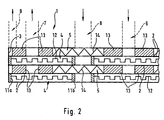
- Fig. 2 the basic structure of such an evaporator unit 1 is shown.
- two plates 2 are connected to each other, preferably by soldering.
- a solder joint 11a extends along the entire circumference of the plates 2.
- all the recesses for the inflow lines 8 for the heat transfer medium are completely surrounded by a further solder joint 11b.
- a closed evaporation chamber 4 is formed between the two plates 2, which is in flow communication only via the recesses for the inflow or outflow line 6, 7 for the medium to be evaporated.
- channel structures for distribution of the medium can be provided.
- such a channel structure 12 is shown schematically. But it is not mandatory. In practice, moreover, the channels would preferably extend in the radial direction.
- the plate pairs 2 soldered together are now stacked with the interposition of annular spacers 13.
- the spacers 13 each surround the recesses for the inflow and outflow lines 6, 7 for the medium to be evaporated and are thus part of the inflow and outflow lines 6, 7.
- structures 14 for distributing the heat transfer medium can additionally be inserted.
- FIG. 2 shows schematically such structures 14. But they are also not mandatory.
- the medium to be evaporated is now introduced into the evaporator unit 1 through the inflow line 6, which extends substantially along the center of the circular plates 2.
- the medium flows in each case via the corresponding recesses in the evaporation chambers 4.
- the spacers 13 between the plate pairs 2 prevent the medium can also flow into the heat transfer chambers 5.
- the medium flows from the inside to the outside and is vaporized by the transferred from the heat transfer chambers 5 thermal energy.
- the volume of the medium increases.
- the flow volume available in the axial direction also increases, so that the flow rate is made uniform despite temperature increase and evaporation, which results in a reduction of the pressure loss.
- the thermal energy required for evaporation and optionally overheating is provided by the heat transfer chambers 5.
- the provision of heat can hereby be accomplished in different ways.
- the heat carrier chambers 5 can be flowed through by a hot heat transfer medium, for example a thermal oil.
- a hot heat transfer medium for example a thermal oil.
- the heat transfer medium through the inflow 8 introduced into the evaporator unit 1 and then flows through the corresponding recesses in the heat transfer chambers 5.
- the heat transfer medium also flows through the heat transfer chambers in the radial direction from the inside to the outside and is then discharged via the corresponding outflow line 9.
- the heat can also be generated directly in the heat transfer chambers 5.
- a fuel gas is introduced as heat transfer medium in the heat transfer chambers 5 and burned directly there catalytically.
- a suitable, for example noble metal-containing catalyst material in the form of a bed or a coating is provided in the heat transfer chambers 5.
- the necessary for the catalytic combustion oxidizing agent, preferably atmospheric oxygen, can be added to the fuel gas or fed directly into the heat transfer chamber 5.
- the maximum thermal energy is provided in the region of the inflow lines 8, while it decreases radially outwards.
- this results from the cooling over the radial run length.
- the fuel gas is depleted according to the radial run length, so that the reaction rate and thus the thermal energy provided decreases.
- the residence time of the depleted fuel gas also increases due to the increase in volume, so that overall better energy utilization and thus a higher conversion rate can be achieved.
- this arrangement has the advantage that exactly where the largest amount of energy is provided, where it is needed.
- the largest energy requirement occurs during the phase transition of the medium to be evaporated, ie in the inlet region. But there is also the largest amount of energy available, as the Thermal oil when entering the heat transfer chamber 5 still has the highest temperature or the fuel gas supplied is still highly enriched.
- a preferred example of application for such an evaporator unit is the evaporation of water and / or methanol in fuel cell systems for mobile applications, for example for use in motor vehicles.
- fuel cells with proton-conducting electrolyte membranes so-called PEM fuel cells
- PEM fuel cells proton-conducting electrolyte membranes
- the hydrogen required for this purpose being generated in the vehicle by steam reforming or partial oxidation.
- steam reforming water and methanol vapor are typically required in a molar ratio of 1: 1 to 2: 1, while pure methanol vapor is used in partial oxidation.
- a gas mixture having a molar ratio of 0-2 parts of steam to a part of methanol gas must generally be prepared.
Landscapes
- Engineering & Computer Science (AREA)
- Physics & Mathematics (AREA)
- Thermal Sciences (AREA)
- Mechanical Engineering (AREA)
- General Engineering & Computer Science (AREA)
- Chemical Kinetics & Catalysis (AREA)
- Chemical & Material Sciences (AREA)
- Fuel Cell (AREA)
- Heat-Exchange Devices With Radiators And Conduit Assemblies (AREA)
- Hydrogen, Water And Hydrids (AREA)
- Ticket-Dispensing Machines (AREA)
- Crystals, And After-Treatments Of Crystals (AREA)
- Polarising Elements (AREA)
Description
- Die Erfindung betrifft eine Verdampfereinheit in Plattenbauweise gemäß dem Oberbegriff des Patentanspruchs 1.
- Aus der DE 44 26 692 C1 ist eine Verdampfereinheit mit rechteckförmigen Platten zum Verdampfen und Überhitzen eines flüssigen Mediums bekannt. Die Zu- und Abströmleitungen für das zu verdampfende Medium und für ein Wärmeträgermedium, die sich jeweils entlang der Stapelrichtung durch den Plattenstapel erstrecken, sind in den Eckbereichen der Platten angeordnet.
- Aus US 4,731,159 ist eine Verdampfereinheit mit kreisförmigen Platten gemäß dem Oberbegriff des Patentanspruchs 1 bekannt.
- Die Aufgabe der Erfindung besteht darin, einen Verdampfer mit geringerem Druckverlust und höherer Umsatzrate zu schaffen.
- Die Aufgabe wird erfindungsgemäß durch die kennzeichnenden Merkmale des Patentanspruchs 1 gelöst.
- Die kreisförmige Ausbildung der Platten und die Anordnung der Zuströmleitungen für das zu verdampfende Medium und für das Wärmeträgermedium im Bereich des Mittelpunktes der Platten und der zugehörigen Abströmleitungen im Bereich des Plattenumfanges führt zu einer Durchströmung der jeweiligen Räume von innen nach außen. Dies ergibt eine Volumenzunahme in radialer Strömungsrichtung und somit eine Vergleichmäßigung der Strömungsgeschwindigkeit trotz Volumenzunahme und somit eine Verringerung des Druckverlusts.
- Wird als Wärmeträgermedium ein Brenngas zur direkten katalytischen Beheizung des wärmeträgerraumes verwendet, so führt die radiale Strömungsführung des Brenngases dazu, daß sich das Brenngas zwar zum Umfang hin abreichert, daß sich gleichzeitig aber auch die Verweilzeit erhöht, so daß insgesamt höhere Umsatzraten erreicht werden können.
- Die Anordnung jeweils einer Zuströmleitung für das Wärmeträgermedium genau zwischen der Zuströmleitung und der Abströmleitung für das zu verdampfende Gas führt zu einer optimalen Wärmeübertragung, da das zu verdampfende Medium nach dem Eintritt in den Verdampfungsraum die Zuströmleitung für das Wärmeträgermedium unströmen muß. Im Bereich der Zuströmleitung für das Wärmeträgermedium ist die zur Verfügung stehende Wärmemenge am größten. Gleichzeitig ist auch der Wärmebedarf im zu verdampfenden Medium direkt nach Eintritt am größten, da dort die Energie für den Phasenübergang umgesetzt wird. Somit wird genau dort am meisten Wärme bereitgestellt, wo sie auch benötigt wird.
- Weitere Vorteile und Ausgestaltungen gehen aus den Unteransprüchen und der Beschreibung hervor. Die Erfindung ist nachstehend anhand einer Prinzipzeichnung näher beschrieben, wobei
- Fig. 1
- den Plattenaufbau einer Verdampfereinheit und
- Fig. 2
- einen vertikalen Schnitt durch die Verdampfereinheit entlang der Linie A-F zeigt.
- Die in der Zeichnung insgesamt mit 1 bezeichnete Verdampfereinheit besteht aus einer Vielzahl von im wesentlichen kreisförmigen Platten 2. Der Plattenstapel wird üblicherweise durch zwei nicht dargestellte Endplatten abgeschlossen. Außerdem wird der Plattenstapel nach außen durch ein Gehäuse 3 begrenzt. Das Gehäuse 3 ist jedoch aus Gründen der Übersichtlichkeit in Fig. 1 nur gestrichelt angedeutet.
- Zwischen benachbarten Platten 2 werden jeweils Verdampfungsräume 4 beziehungsweise Wärmeträgerräume 5 gebildet. Vorzugsweise werden die Verdampfungs- und Wärmeträgerräume 4, 5 abwechselnd angeordnet. Zum Zu- und Abführen des zu verdampfenden Mediums und des Wärmeträgermediums sind entsprechende Zu- und Abströmleitungen 6-9 vorgesehen, die sich in Stapelrichtung durch die Verdampfereinheit 1 erstrecken. Hierzu sind in allen Platten 2 identische Ausnehmungen angeordnet.
- In jeder im wesentlichen kreisförmigen Platte 2 ist im Bereich des Mittelpunktes eine Ausnehmung zur Ausbildung der Zuströmleitung 6 für das zu verdampfende Medium vorgesehen. Am Umfang der Platten sind weiterhin mehrere Vorsprünge 10, vorzugsweise kreissymmetrisch angeordnet. In jedem dieser Vorsprünge 10 ist eine Ausnehmung zur Ausbildung der Abströmleitungen 7 für das verdampfte Medium vorgesehen. Weiterhin ist zwischen der Zuström- und der Abströmleitung 6, 7 für das zu verdampfende Medium und mit radialem Abstand von der Zuströmleitung 6 jeweils eine Ausnehmung zur Ausbildung der Zuströmleitung 8 für das Wärmeträgermedium vorgesehen. Die Abströmleitungen 9 für das Wärmeträgertmedium werden schließlich durch die Räume zwischen den Platten 2 und dem Gehäuse 3 gebildet.
- In Fig. 2 ist der prinzipielle Aufbau einer solchen Verdampfereinheit 1 gezeigt. Beim Zusammenbau der Verdampfereinheit 1 werden jeweils zwei Platten 2 miteinander verbunden, vorzugsweise durch Löten. Eine Lötverbindung 11a erstreckt sich entlang des gesamten Umfanges der Platten 2. Zusätzlich sind alle Ausnehmungen für die Zuströmleitungen 8 für das Wärmeträgermedium mit einer weiteren Lötverbindung 11b vollständig umgeben. Somit wird zwischen den beiden Platten 2 ein abgeschlossener Verdampfungsraum 4 gebildet, der nur über die Ausnehmungen für die Zu- beziehungsweise Abströmleitung 6, 7 für das zu verdampfende Medium in Strömungsverbindung steht. Im den Verdampfungsräumen 4 können Kanalstrukturen zur Verteilung des Mediums vorgesehen werden. In Fig. 2 ist eine solche Kanalstruktur 12 schematisch eingezeichnet. Sie ist aber nicht zwingend erforderlich. In der Praxis würden sich die Kanäle außerdem vorzugsweise in radialer Richtung erstrecken.
- Die so zusammen gelöteten Plattenpaare 2 werden nun unter Zwischenfügen von ringförmigen Abstandshaltern 13 aufeinander gestapelt. Die Abstandshalter 13 umgeben jeweils die Ausnehmungen für die Zu- und Abströmleitungen 6, 7 für das zu verdampfende Medium und sind somit Bestandteil der Zu- und Abströmleitungen 6, 7. Neben den Abstandshaltern können zusätzlich noch Strukturen 14 zur Verteilung des Wärmeträgermediums eingefügt werden. In Fig. 2 sind solche Strukturen 14 schematisch eingezeichnet. Sie sind aber ebenfalls nicht zwingend erforderlich. Beim Stapeln bilden sich somit zwischen den Plattenpaare 2 Wärmeträgerräume 5 aus, die mit den Zubeziehungsweise Abströmleitungen 6, 7 für das zu verdampfende Medium nicht in Strömungsverbindung stehen.
- Im Betrieb wird nun das zu verdampfende Medium durch die Zuströmleitung 6, die sich im wesentlichen entlang des Mittelpunktes der kreisförmigen Platten 2 erstreckt, in die Verdampfereinheit 1 eingeleitet. Das Medium strömt jeweils über die entsprechenden Ausnehmungen in die Verdampfungsräume 4. Die Abstandshalter 13 zwischen den Plattenpaaren 2 verhindern, daß das Medium auch in die Wärmeträgerräume 5 einströmen kann. Innerhalb der Verdampfungsräume 4 strömt das Medium von innen nach außen und wird dabei durch die aus den Wärmeträgerräumen 5 übertragene thermische Energie verdampft. Beim Verdampfen nimmt das Volumen des Mediums zu. Gleichzeitig nimmt aber auch das zur Verfügung stehende Strömungsvolumen in axialer Richtung zu, so daß die Strömungsgeschwindigkeit trotz Temperaturerhöhung und Verdampfung vergleichmäßigt wird, was zu eine Verringerung des Druckverlustes bewirkt.
- Die zur Verdampfung und gegebenenfalls Überhitzung benötigte thermische Energie wird durch die Wärmeträgerräume 5 zur Verfügung gestellt. Die Bereitstellung der Wärme kann hierbei auf unterschiedliche Art und Weise bewerkstelligt werden. Zum einen können die Wärmeträgerräume 5 von einem heißen Wärmeträgermedium, beispielsweise einem Thermoöl, durchströmt werden. Hierzu wird das Wärmeträgermedium durch die Zuströmleitungen 8 in die Verdampfereinheit 1 eingebracht und strömt dann über die entsprechenden Ausnehmungen in die Wärmeträgerräume 5. Durch die Lötverbindungen 11b im Bereich dieser Ausnehmungen wird verhindert, daß das Wärmeträgermedium in die Verdampfungsräume 4 strömen kann. Das Wärmeträgermedium durchströmt die Wärmeträgerräume ebenfalls in radialer Richtung von innen nach außen und wird anschließend über die entsprechende Abströmleitung 9 abgeführt.
- Die Wärme kann jedoch auch direkt in den Wärmeträgerräumen 5 erzeugt werden. Hierzu wird anstelle des Thermoöls ein Brenngas als Wärmeträgermedium in die Wärmeträgerräume 5 eingeleitet und dort direkt katalytisch verbrannt. Hierzu wird in den Wärmeträgerräumen 5 ein geeignetes, beispielsweise edelmetallhaltiges Katalysatormaterial in Form einer Schüttung oder einer Beschichtung vorgesehen. Das für die katalytische Verbrennung notwendige Oxidationsmittel, vorzugsweise Luftsauerstoff, kann dem Brenngas beigemischt oder aber direkt in den Wärmeträgerraum 5 zugeführt werden.
- In beiden Fällen wird die maximale thermische Energie im Bereich der Zuströmleitungen 8 zur Verfügung gestellt, während sie radial nach außen abnimmt. Bei Verwendung eines Thermoöls resultiert dies durch die Abkühlung über die radiale Lauflänge. Bei der direkten katalytischen Beheizung wird das Brenngas entsprechend über die radiale Lauflänge abgereichert, so daß die Reaktionsrate und damit die bereitgestellte thermische Energie abnimmt. Gleichzeitig nimmt aber die Verweilzeit des abgereicherten Brenngases durch die Volumenzunahme ebenfalls zu, so daß insgesamt eine bessere Energieausnutzung und somit eine höhere Umsatzrate erreicht werden kann.
- Weiterhin bietet diese Anordnung den Vorteil, daß genau dort die größte Energiemenge bereitgestellt wird, wo sie auch benötigt wird. Der größte Energiebedarf tritt beim Phasenübergang des zu verdampfenden Mediums, also im Eintrittsbereich auf. Dort wird aber auch die größte Energiemenge zur Verfügung gestellt, da das Thermoöl beim Eintritt in den Wärmeträgerraum 5 noch die höchste Temperatur hat beziehungsweise das zugeführte Brenngas noch hoch angereichert ist.
- Durch die Anordnung der Zuströmleitungen 8 für das Wärmeträgermedium genau zwischen der Zu- und den Abströmleitungen 7 für das zu verdampfende Medium werden Bypasströme und somit Tröpfchenbildung im verdampften Medium verhindert. Das zu verdampfende Medium muß zwangsläufig auf seinem Weg von der Zu- zur Abströmleitung 6, 7 in Kontakt mit dem Wärmeträgermedium kommen, da der direkte radiale Strömungsweg durch die Zuströmleitung 8 für das Wärmeträgermedium versperrt wird. Ein weiterer Vorteil dieser Anordnung besteht schließlich noch in der thermomechanischen Entkopplung des Plattenstapels in Richtung der Plattennormalen.
- Ein bevorzugtes Anwendungsbeispiel für eine solche Verdampfereinheit ist die Verdampfung von Wasser und/oder Methanol in Brennstoffzellensystemen für mobile Anwendungen, beispielsweise für den Einsatz in Kraftfahrzeugen. Hierzu werden vorzugsweise Brennstoffzellen mit protonenleitenden Elektrolytmembranen, sogenannte PEM-Brennstoffzellen, verwendet, wobei der hierfür benötigte Wasserstoff im Fahrzeug durch Wasserdampfreformierung oder partielle Oxidation erzeugt wird. Bei beiden Prozessen ist es notwendig, die Flüssigkeit vor dem Eintritt in den Reformer zu verdampfen und auf ungefähr 250° C zu überhitzen. Bei der Wasserdampfreformierung werden Wasser- und Methanoldampf typischerweise im Molverhältnis 1:1 bis 2:1 benötigt, während bei der partiellen Oxidation reiner Methanoldampf verwendet wird. Da jedoch Mischformen aus beiden Reaktionen realisiert werden können, muß generell ein Gasgemisch mit einem Molverhältnis von 0-2 Teilen Wasserdampf zu einem Teil Methanolgas hergestellt werden.
Claims (6)
- Verdampfereinheit (1) in Plattenbauweise, wobei zwischen aufeinanderfolgenden Platten (2) jeweils Verdampfungsräume (4) beziehungsweise Wärmeträgerräume (5) ausgebildet sind, mit im wesentlichen senkrecht zu den Platten (2) verlaufenden Zuströmleitung und Abströmleitungen (6, 7) für ein zu verdampfendes Medium beziehungsweise für ein Wärmeträgermedium,
wobei die Platten (2) im wesentlichen kreisförmig ausgebildet sind, wobei die Zuströmleitung (6) für das zu verdampfende Medium im Bereich des Mittelpunktes der kreisförmigen Platten (2) angeordnet ist, dadurch gekennzeichnet, daß mehrere Zuströmleitungen (8) für das Wärmeträgermedium vorgesehen sind, die mit radialem Abstand vom Mittelpunkt der kreisförmigen Platten (2) angeordnet sind, und daß die Abströmleitungen (7, 9) für das verdampfte Medium und für das Wärmeträgermedium im Bereich des Umfanges der kreisförmigen Platten (2) angeordnet sind. - Verdampfereinheit nach Anspruch 1,
dadurch gekennzeichnet,
daß das Wärmeträgermedium ein Thermoöl oder ein Brenngas zur direkten katalytischen Beheizung der Wärmeträgerräume (5) ist. - Verdampfereinheit nach Anspruch 1,
dadurch gekennzeichnet,
daß die Zuströmleitungen (8) für das Wärmeträgermedium kreissymmetrisch zum Mittelpunkt der im wesentlichen kreisförmigen Platten (2) angeordnet sind. - Verdampfereinheit nach Anspruch 1,
dadurch gekennzeichnet,
daß mehrere Abströmleitungen (7) für das verdampfte Medium vorgesehen sind, die kreissymmetrisch im Bereich des Plattenumfangs angeordnet sind. - Verdampfereinheit nach Anspruch 1,
dadurch gekennzeichnet,
daß eine identische Zahl von Zuströmleitungen (8) für das Wärmeträgermedium und von Abströmleitungen (7) für das verdampfte Medium vorgesehen sind und daß jeweils zwischen der Zuströmleitung (6) für das zu verdampfende Medium und einer Abströmleitung (7) für das verdampfte Medium eine Zuströmleitung (8) für das Wärmeträgermedium angeordnet ist. - Verdampfereinheit nach Anspruch 1,
dadurch gekennzeichnet,
daß der Plattenstapel in einem zylindrischen Gehäuse (3) angeordnet ist und daß der Plattenstapel zumindest in Teilbereichen des Umfanges nicht am Gehäuse (3) anliegt und daß diese Aussparungen zwischen Plattenumfang und Gehäuse (3) als Abströmleitung (9) für das Wärmeträgermedium ausgeführt sind.
Applications Claiming Priority (2)
| Application Number | Priority Date | Filing Date | Title |
|---|---|---|---|
| DE19847213A DE19847213C1 (de) | 1998-10-13 | 1998-10-13 | Verdampfereinheit |
| DE19847213 | 1998-10-13 |
Publications (3)
| Publication Number | Publication Date |
|---|---|
| EP0994299A2 EP0994299A2 (de) | 2000-04-19 |
| EP0994299A3 EP0994299A3 (de) | 2004-03-03 |
| EP0994299B1 true EP0994299B1 (de) | 2007-05-23 |
Family
ID=7884351
Family Applications (1)
| Application Number | Title | Priority Date | Filing Date |
|---|---|---|---|
| EP99118142A Expired - Lifetime EP0994299B1 (de) | 1998-10-13 | 1999-09-11 | Verdampfereinheit |
Country Status (4)
| Country | Link |
|---|---|
| US (1) | US6152216A (de) |
| EP (1) | EP0994299B1 (de) |
| AT (1) | ATE363054T1 (de) |
| DE (2) | DE19847213C1 (de) |
Families Citing this family (13)
| Publication number | Priority date | Publication date | Assignee | Title |
|---|---|---|---|---|
| EP1085260A1 (de) | 1999-09-15 | 2001-03-21 | XCELLSIS GmbH | Verdampfer |
| DE19947923B4 (de) * | 1999-09-15 | 2005-10-27 | Ballard Power Systems Ag | Plattenreaktor eines Gaserzeugungssystems für ein Brennstoffzellensystem |
| DE10009179C2 (de) * | 2000-02-26 | 2002-07-18 | Xcellsis Gmbh | Wärmeübertrager in Plattenbauweise |
| US6811592B2 (en) * | 2002-03-01 | 2004-11-02 | Johnson & Johnson Vision Care, Inc. | Thin film in-line degasser |
| US7717982B2 (en) * | 2003-02-26 | 2010-05-18 | Johnson & Johnson Vision Care, Inc. | Thin film in-line degasser |
| US20050205215A1 (en) * | 2004-03-17 | 2005-09-22 | General Electric Company | Apparatus for the evaporation of aqueous organic liquids and the production of powder pre-forms in flame hydrolysis processes |
| DE102005017452B4 (de) * | 2005-04-15 | 2008-01-31 | INSTITUT FüR MIKROTECHNIK MAINZ GMBH | Mikroverdampfer |
| DE102005044291A1 (de) * | 2005-09-16 | 2007-03-29 | Behr Industry Gmbh & Co. Kg | Stapelscheiben-Wärmeübertrager, insbesondere Ladeluftkühler |
| FR2914409A1 (fr) * | 2007-03-26 | 2008-10-03 | Bousquet Adrien Laude | Disque refrigerant pour installation de stockage et de regeneration d'un fluide frigo-porteur |
| GB2459480B8 (en) * | 2008-04-23 | 2013-07-24 | Denso Corp | A heat exchanger, a method of making a heat exchanger and a kit of parts for making a heat exchanger |
| EP2719984A1 (de) * | 2012-10-09 | 2014-04-16 | ABB Technology Ltd | Dampfphasentrocknungsgerät |
| CN104896986B (zh) * | 2015-06-09 | 2017-03-22 | 江苏科技大学 | 一种高效紧凑式lng汽化器 |
| CN111974014B (zh) * | 2020-08-18 | 2021-06-11 | 无锡化工装备股份有限公司 | 一种降膜式再沸器的多层液体分布装置及方法 |
Family Cites Families (9)
| Publication number | Priority date | Publication date | Assignee | Title |
|---|---|---|---|---|
| GB8305595D0 (en) * | 1983-03-01 | 1983-03-30 | Ici Plc | Evaporator |
| CA1265289A (en) * | 1985-12-16 | 1990-01-30 | Viney Pal Aneja | Method and apparatus for devolatilizing polymer solutions |
| US5470431A (en) * | 1990-08-20 | 1995-11-28 | Showa Aluminum Corp. | Stack type evaporator |
| US5152337A (en) * | 1989-08-30 | 1992-10-06 | Honda Giken Kogyo | Stack type evaporator |
| US5514248A (en) * | 1990-08-20 | 1996-05-07 | Showa Aluminum Corporation | Stack type evaporator |
| US5453158A (en) * | 1994-03-10 | 1995-09-26 | The Dow Chemical Company | Polymer devolatilizer |
| DE4426692C1 (de) * | 1994-07-28 | 1995-09-14 | Daimler Benz Ag | Zweistufige Verdampfereinheit für einen Reaktant-Massenstrom und Verfahren zur Herstellung desselben |
| DE19510847C2 (de) * | 1995-03-17 | 2002-11-21 | Michael Rehberg | Plattenwärmetauscher |
| US5937935A (en) * | 1997-12-17 | 1999-08-17 | Ford Motor Company | Heat exchanger and method of making the same |
-
1998
- 1998-10-13 DE DE19847213A patent/DE19847213C1/de not_active Expired - Fee Related
-
1999
- 1999-09-11 AT AT99118142T patent/ATE363054T1/de not_active IP Right Cessation
- 1999-09-11 DE DE59914343T patent/DE59914343D1/de not_active Expired - Lifetime
- 1999-09-11 EP EP99118142A patent/EP0994299B1/de not_active Expired - Lifetime
- 1999-10-13 US US09/417,309 patent/US6152216A/en not_active Expired - Fee Related
Also Published As
| Publication number | Publication date |
|---|---|
| DE19847213C1 (de) | 2000-02-10 |
| ATE363054T1 (de) | 2007-06-15 |
| DE59914343D1 (de) | 2007-07-05 |
| US6152216A (en) | 2000-11-28 |
| EP0994299A2 (de) | 2000-04-19 |
| EP0994299A3 (de) | 2004-03-03 |
Similar Documents
| Publication | Publication Date | Title |
|---|---|---|
| DE69806658T2 (de) | Vorrichtung für die Reformierung von Kraftstoffen | |
| DE69709348T2 (de) | Thermisch verbesserte kompakte reformieranlage | |
| DE60128159T2 (de) | Vorrichtung zur reformierung von Brennstoff | |
| DE19847213C1 (de) | Verdampfereinheit | |
| DE69217132T2 (de) | Brennstoffzellenstapel mit vollständig im Innern angeordneten Sammelkanälen | |
| EP0638140B1 (de) | Reaktor zur katalytischen behandlung gasförmiger fluide | |
| DE10151665B4 (de) | Eine Gas/Flüssigkeit-Trenneinrichtung, insbesondere zur Anwendung in einem Brennstoffzellensystem | |
| DE4426692C1 (de) | Zweistufige Verdampfereinheit für einen Reaktant-Massenstrom und Verfahren zur Herstellung desselben | |
| DE69108104T2 (de) | Brennstoffzellenstapel mit interner Reformierung und vollständig in Innern angeordneten Sammelkanälen. | |
| DE19754012C2 (de) | Anlage zur Wasserdampfreformierung eines Kohlenwasserstoffs | |
| EP3111499B1 (de) | Brennstoffzellensystem | |
| EP0687648A1 (de) | Zweistufige Methanol-Reformierung | |
| EP1013331A1 (de) | Membranmodul zur selektiven Gasabtrennung in Plattenstapelbauweise | |
| DE112004001696T5 (de) | Verdampfer und Verfahren zum Verdampfen | |
| DE602004004893T2 (de) | Verfahren und ausrüstung zur verteilung von zwei fluiden in die und aus den kanälen in einer monolithischen struktur mit mehreren kanälen und ihre verwendung | |
| EP1402589B8 (de) | Vorrichtung und verfahren zum verdampfen flüssiger medien | |
| EP1815548A2 (de) | Vorrichtung zur durchführung einer chemischen reaktion | |
| DE10001064B4 (de) | Reformierungsreaktor in Schichtbauweise | |
| EP1178552B1 (de) | Brennstoffzellensystem | |
| EP0976446B1 (de) | Reaktoreinheit in einem System zur Erzeugung eines wasserstoffreichen Gases aus einem flüssigen Rohkraftstoff | |
| DE19903168C2 (de) | Spiralwärmetauscher | |
| EP1205000B1 (de) | Kühlsystem für brennstoffzellen und verfahren zum betreiben desselben | |
| DE112013006536B4 (de) | Brennstoffzellenmodul | |
| DE10010400C2 (de) | Vorrichtung und Verfahren zum Erhitzen und/oder Verdampfen flüssiger oder gasförmiger Medien | |
| EP0735602B1 (de) | Wärmetauscher in Plattenbauweise mit Reformer |
Legal Events
| Date | Code | Title | Description |
|---|---|---|---|
| PUAI | Public reference made under article 153(3) epc to a published international application that has entered the european phase |
Free format text: ORIGINAL CODE: 0009012 |
|
| AK | Designated contracting states |
Kind code of ref document: A2 Designated state(s): AT BE CH CY DE DK ES FI FR GB GR IE IT LI LU MC NL PT SE |
|
| AX | Request for extension of the european patent |
Free format text: AL;LT;LV;MK;RO;SI |
|
| RAP1 | Party data changed (applicant data changed or rights of an application transferred) |
Owner name: XCELLSIS GMBH |
|
| RAP1 | Party data changed (applicant data changed or rights of an application transferred) |
Owner name: BALLARD POWER SYSTEMS AG |
|
| PUAL | Search report despatched |
Free format text: ORIGINAL CODE: 0009013 |
|
| AK | Designated contracting states |
Kind code of ref document: A3 Designated state(s): AT BE CH CY DE DK ES FI FR GB GR IE IT LI LU MC NL PT SE |
|
| AX | Request for extension of the european patent |
Extension state: AL LT LV MK RO SI |
|
| 17P | Request for examination filed |
Effective date: 20040903 |
|
| AKX | Designation fees paid |
Designated state(s): AT BE CH CY DE DK ES FI FR GB GR IE IT LI LU MC NL PT SE |
|
| RAP1 | Party data changed (applicant data changed or rights of an application transferred) |
Owner name: NUCELLSYS GMBH |
|
| GRAP | Despatch of communication of intention to grant a patent |
Free format text: ORIGINAL CODE: EPIDOSNIGR1 |
|
| GRAS | Grant fee paid |
Free format text: ORIGINAL CODE: EPIDOSNIGR3 |
|
| GRAA | (expected) grant |
Free format text: ORIGINAL CODE: 0009210 |
|
| AK | Designated contracting states |
Kind code of ref document: B1 Designated state(s): AT BE CH CY DE DK ES FI FR GB GR IE IT LI LU MC NL PT SE |
|
| PG25 | Lapsed in a contracting state [announced via postgrant information from national office to epo] |
Ref country code: FI Free format text: LAPSE BECAUSE OF FAILURE TO SUBMIT A TRANSLATION OF THE DESCRIPTION OR TO PAY THE FEE WITHIN THE PRESCRIBED TIME-LIMIT Effective date: 20070523 |
|
| REG | Reference to a national code |
Ref country code: GB Ref legal event code: FG4D Free format text: NOT ENGLISH |
|
| REG | Reference to a national code |
Ref country code: CH Ref legal event code: EP |
|
| REG | Reference to a national code |
Ref country code: IE Ref legal event code: FG4D Free format text: LANGUAGE OF EP DOCUMENT: GERMAN |
|
| REF | Corresponds to: |
Ref document number: 59914343 Country of ref document: DE Date of ref document: 20070705 Kind code of ref document: P |
|
| GBT | Gb: translation of ep patent filed (gb section 77(6)(a)/1977) |
Effective date: 20070705 |
|
| PG25 | Lapsed in a contracting state [announced via postgrant information from national office to epo] |
Ref country code: SE Free format text: LAPSE BECAUSE OF FAILURE TO SUBMIT A TRANSLATION OF THE DESCRIPTION OR TO PAY THE FEE WITHIN THE PRESCRIBED TIME-LIMIT Effective date: 20070823 |
|
| PG25 | Lapsed in a contracting state [announced via postgrant information from national office to epo] |
Ref country code: ES Free format text: LAPSE BECAUSE OF FAILURE TO SUBMIT A TRANSLATION OF THE DESCRIPTION OR TO PAY THE FEE WITHIN THE PRESCRIBED TIME-LIMIT Effective date: 20070903 |
|
| ET | Fr: translation filed | ||
| NLV1 | Nl: lapsed or annulled due to failure to fulfill the requirements of art. 29p and 29m of the patents act | ||
| REG | Reference to a national code |
Ref country code: IE Ref legal event code: FD4D |
|
| PG25 | Lapsed in a contracting state [announced via postgrant information from national office to epo] |
Ref country code: PT Free format text: LAPSE BECAUSE OF FAILURE TO SUBMIT A TRANSLATION OF THE DESCRIPTION OR TO PAY THE FEE WITHIN THE PRESCRIBED TIME-LIMIT Effective date: 20071023 Ref country code: NL Free format text: LAPSE BECAUSE OF FAILURE TO SUBMIT A TRANSLATION OF THE DESCRIPTION OR TO PAY THE FEE WITHIN THE PRESCRIBED TIME-LIMIT Effective date: 20070523 Ref country code: IE Free format text: LAPSE BECAUSE OF FAILURE TO SUBMIT A TRANSLATION OF THE DESCRIPTION OR TO PAY THE FEE WITHIN THE PRESCRIBED TIME-LIMIT Effective date: 20070523 Ref country code: DK Free format text: LAPSE BECAUSE OF FAILURE TO SUBMIT A TRANSLATION OF THE DESCRIPTION OR TO PAY THE FEE WITHIN THE PRESCRIBED TIME-LIMIT Effective date: 20070523 |
|
| PLBE | No opposition filed within time limit |
Free format text: ORIGINAL CODE: 0009261 |
|
| STAA | Information on the status of an ep patent application or granted ep patent |
Free format text: STATUS: NO OPPOSITION FILED WITHIN TIME LIMIT |
|
| BERE | Be: lapsed |
Owner name: NUCELLSYS G.M.B.H. Effective date: 20070930 |
|
| 26N | No opposition filed |
Effective date: 20080226 |
|
| PG25 | Lapsed in a contracting state [announced via postgrant information from national office to epo] |
Ref country code: MC Free format text: LAPSE BECAUSE OF NON-PAYMENT OF DUE FEES Effective date: 20070930 Ref country code: GR Free format text: LAPSE BECAUSE OF FAILURE TO SUBMIT A TRANSLATION OF THE DESCRIPTION OR TO PAY THE FEE WITHIN THE PRESCRIBED TIME-LIMIT Effective date: 20070824 |
|
| REG | Reference to a national code |
Ref country code: CH Ref legal event code: PL |
|
| PG25 | Lapsed in a contracting state [announced via postgrant information from national office to epo] |
Ref country code: LI Free format text: LAPSE BECAUSE OF NON-PAYMENT OF DUE FEES Effective date: 20070930 Ref country code: CH Free format text: LAPSE BECAUSE OF NON-PAYMENT OF DUE FEES Effective date: 20070930 |
|
| PG25 | Lapsed in a contracting state [announced via postgrant information from national office to epo] |
Ref country code: BE Free format text: LAPSE BECAUSE OF NON-PAYMENT OF DUE FEES Effective date: 20070930 |
|
| PG25 | Lapsed in a contracting state [announced via postgrant information from national office to epo] |
Ref country code: AT Free format text: LAPSE BECAUSE OF NON-PAYMENT OF DUE FEES Effective date: 20070911 |
|
| PG25 | Lapsed in a contracting state [announced via postgrant information from national office to epo] |
Ref country code: CY Free format text: LAPSE BECAUSE OF FAILURE TO SUBMIT A TRANSLATION OF THE DESCRIPTION OR TO PAY THE FEE WITHIN THE PRESCRIBED TIME-LIMIT Effective date: 20070523 |
|
| PG25 | Lapsed in a contracting state [announced via postgrant information from national office to epo] |
Ref country code: LU Free format text: LAPSE BECAUSE OF NON-PAYMENT OF DUE FEES Effective date: 20070911 |
|
| PGFP | Annual fee paid to national office [announced via postgrant information from national office to epo] |
Ref country code: GB Payment date: 20090922 Year of fee payment: 11 |
|
| PGFP | Annual fee paid to national office [announced via postgrant information from national office to epo] |
Ref country code: IT Payment date: 20090925 Year of fee payment: 11 |
|
| GBPC | Gb: european patent ceased through non-payment of renewal fee |
Effective date: 20100911 |
|
| PG25 | Lapsed in a contracting state [announced via postgrant information from national office to epo] |
Ref country code: IT Free format text: LAPSE BECAUSE OF NON-PAYMENT OF DUE FEES Effective date: 20100911 |
|
| PGFP | Annual fee paid to national office [announced via postgrant information from national office to epo] |
Ref country code: DE Payment date: 20110311 Year of fee payment: 12 |
|
| REG | Reference to a national code |
Ref country code: FR Ref legal event code: ST Effective date: 20110531 |
|
| PG25 | Lapsed in a contracting state [announced via postgrant information from national office to epo] |
Ref country code: FR Free format text: LAPSE BECAUSE OF NON-PAYMENT OF DUE FEES Effective date: 20100930 |
|
| PG25 | Lapsed in a contracting state [announced via postgrant information from national office to epo] |
Ref country code: GB Free format text: LAPSE BECAUSE OF NON-PAYMENT OF DUE FEES Effective date: 20100911 |
|
| PGFP | Annual fee paid to national office [announced via postgrant information from national office to epo] |
Ref country code: FR Payment date: 20091001 Year of fee payment: 11 |
|
| REG | Reference to a national code |
Ref country code: DE Ref legal event code: R119 Ref document number: 59914343 Country of ref document: DE Effective date: 20120403 |
|
| PG25 | Lapsed in a contracting state [announced via postgrant information from national office to epo] |
Ref country code: DE Free format text: LAPSE BECAUSE OF NON-PAYMENT OF DUE FEES Effective date: 20120403 |