EP0993376B1 - Auf abruf arbeitende tintenstrahldruckvorrichtung - Google Patents
Auf abruf arbeitende tintenstrahldruckvorrichtung Download PDFInfo
- Publication number
- EP0993376B1 EP0993376B1 EP98932354A EP98932354A EP0993376B1 EP 0993376 B1 EP0993376 B1 EP 0993376B1 EP 98932354 A EP98932354 A EP 98932354A EP 98932354 A EP98932354 A EP 98932354A EP 0993376 B1 EP0993376 B1 EP 0993376B1
- Authority
- EP
- European Patent Office
- Prior art keywords
- ink
- nozzle
- nozzle axis
- ink chamber
- chamber
- Prior art date
- Legal status (The legal status is an assumption and is not a legal conclusion. Google has not performed a legal analysis and makes no representation as to the accuracy of the status listed.)
- Expired - Lifetime
Links
- 238000007641 inkjet printing Methods 0.000 title claims description 14
- 238000000034 method Methods 0.000 claims description 13
- 230000005684 electric field Effects 0.000 claims description 12
- 230000000694 effects Effects 0.000 claims description 9
- 239000000463 material Substances 0.000 claims description 4
- 238000004891 communication Methods 0.000 claims description 2
- 230000001419 dependent effect Effects 0.000 claims 3
- 239000000976 ink Substances 0.000 description 105
- 239000011159 matrix material Substances 0.000 description 11
- 238000004519 manufacturing process Methods 0.000 description 7
- 238000000151 deposition Methods 0.000 description 2
- 238000000465 moulding Methods 0.000 description 2
- 238000004544 sputter deposition Methods 0.000 description 2
- 238000002679 ablation Methods 0.000 description 1
- 239000000853 adhesive Substances 0.000 description 1
- 230000001070 adhesive effect Effects 0.000 description 1
- 230000004888 barrier function Effects 0.000 description 1
- 238000009833 condensation Methods 0.000 description 1
- 230000005494 condensation Effects 0.000 description 1
- 230000008021 deposition Effects 0.000 description 1
- 238000006073 displacement reaction Methods 0.000 description 1
- 238000005530 etching Methods 0.000 description 1
- 238000011066 ex-situ storage Methods 0.000 description 1
- 239000012530 fluid Substances 0.000 description 1
- 238000000227 grinding Methods 0.000 description 1
- 238000011065 in-situ storage Methods 0.000 description 1
- 238000009413 insulation Methods 0.000 description 1
- 238000003754 machining Methods 0.000 description 1
- 238000002161 passivation Methods 0.000 description 1
- 238000007639 printing Methods 0.000 description 1
- 239000000758 substrate Substances 0.000 description 1
- XLYOFNOQVPJJNP-UHFFFAOYSA-N water Substances O XLYOFNOQVPJJNP-UHFFFAOYSA-N 0.000 description 1
Images



Classifications
-
- B—PERFORMING OPERATIONS; TRANSPORTING
- B41—PRINTING; LINING MACHINES; TYPEWRITERS; STAMPS
- B41J—TYPEWRITERS; SELECTIVE PRINTING MECHANISMS, i.e. MECHANISMS PRINTING OTHERWISE THAN FROM A FORME; CORRECTION OF TYPOGRAPHICAL ERRORS
- B41J2/00—Typewriters or selective printing mechanisms characterised by the printing or marking process for which they are designed
- B41J2/005—Typewriters or selective printing mechanisms characterised by the printing or marking process for which they are designed characterised by bringing liquid or particles selectively into contact with a printing material
- B41J2/01—Ink jet
- B41J2/135—Nozzles
- B41J2/14—Structure thereof only for on-demand ink jet heads
- B41J2/14201—Structure of print heads with piezoelectric elements
- B41J2/14282—Structure of print heads with piezoelectric elements of cantilever type
Definitions
- This invention relates to drop on demand ink jet printing apparatus and, in one example, to drop on demand ink jet printing apparatus having a two dimensional array of ink chambers.
- Drop on demand ink jet printing apparatus typically comprise a chamber supplied with droplet fluid and communicating with a nozzle for ejection of droplets therefrom, and means actuable by electrical signals to vary the volume of the chamber, the volume variation being sufficient to effect droplet ejection.
- WO88/10192 see preamble of claims 1 and 23, and DE 196 39 717 each describe an ink jet printing head containing pressure chambers of approximately circular configuration.
- Each pressure chamber has a piezotransducer on one side which when actuated bulges outwards and ejects ink droplets though a nozzle.
- the present invention provides drop-on-demand ink jet printing apparatus, comprising a nozzle on a nozzle axis; an ink chamber extending radially about the nozzle axis; ink supply means communicating with the ink chamber; and an actuator movable in the direction of the nozzle axis to effect ejection of an ink drop through the nozzle and replenishment of the ink chamber with ink; characterised in that the ink chamber is bounded by a generally circular structure providing through a change in ink depth in the direction of the nozzle axis a change in acoustic impedance serving to reflect acoustic waves travelling in the ink chamber radially of the nozzle axis due to said motion of the actuator for convergence at the nozzle axis, said actuator effecting thereby ink drop ejection through acoustic wave travel in the ink chamber radially of the nozzle axis.
- the ink chamber extends a radial distance R from the nozzle axis, the actuator being movable in the direction of the nozzle between first and second configurations in a time which is at least half of the time R/c, where c is the speed of sound through ink in the ink chamber.
- the nozzle is moveable between configurations in a time which is at most 500ns.
- the nozzle is moveable between configurations in a time which is at least an order of magnitude less than the time R/c, more preferably of an order of nanoseconds.
- the actuator comprises a piezoelectric actuating disc associated with the ink chamber and moveable to or from a domed configuration to effect ink drop ejection, the apparatus further comprising electrodes for applying an actuating electric field to the piezoelectric disc.
- the piezoelectric disc is homogeneous and so poled in relation to the actuating electric field as to move in shear mode. If so, the electric field may be applied in the direction of the nozzle axis, the piezoelectric disc being poled radially.
- the piezoelectric disc may be poled in directions which all converge towards the nozzle axis.
- the electrodes may comprise a ground electrode on a face of the piezoelectric disc abutting the ink chamber and another electrode on an opposing face of the piezoelectric disc.
- the disc may be provided with a projecting member projecting along the nozzle axis, or with a recess substantially concentric with the nozzle.
- the ink supply means may serve to supply ink to the ink chamber in a direction radially of the nozzle axis.
- the ink supply means may serve to supply ink to the ink chamber at a plurality of locations disposed circumferentially about the ink chamber, preferably serving to supply ink to the ink chamber around substantially the entire periphery of the ink chamber.
- the generally circular structure may define an annulus of ink about the ink chamber which in the direction of the nozzle axis is of a depth different from the depth of the ink chamber. This annulus may form part of the ink supply means.
- the apparatus comprises a plurality of said nozzles, each having a respective nozzle axis, said nozzles being provided in parallel and in a two dimensional planar array; a plurality of said ink chambers, each extending about a respective nozzle axis; and a homogeneous piezoelectric sheet having a two dimensional array of said actuators, each actuator being associated with a respective ink chamber.
- the apparatus may comprise a plurality of said electrodes, one common ground electrode on a face of the piezoelectric sheet abutting the ink chambers and on an opposing face, individual electrodes associated respectively with the ink chambers.
- the individual electrodes may be connected to electrical pulse applying means through respective electrical connections provided on an interconnection plate laminated with the nozzle plate and the piezoelectric sheet.
- the nozzles may be formed in a nozzle plate, said nozzle plate being laminated with the piezoelectric sheet to provide said plurality of ink chambers.
- the ink supply means may comprise an array of ink channels formed in said piezoelectric sheet, and ink transfer means for transferring ink from the ink channels to the ink chambers.
- the ink transfer means may comprise an array of recesses formed in an intermediate plate laminated with the nozzle plate and the piezoelectric sheet.
- the nozzle plate, interconnection plate and intermediate plate may each comprise a piezoelectric sheet.
- the nozzle plate, interconnection plate and intermediate plate may each comprise a sheet of material thermally compatible with the piezoelectric sheet.
- the present invention provides a method of ink jet printing comprising the steps of establishing a planar body of ink in communication with a nozzle having a nozzle axis, the body of ink extending radially of the nozzle axis; characterised by providing in the body of ink through a change in ink depth in the direction of the nozzle axis an impedance boundary extending circumferentially of the nozzle axis; and selectively moving an actuator in the direction of the nozzle axis so as to establish acoustic waves travelling radially of the nozzle axis in the ink chamber, the waves being reflected by the impedance boundary and converging at the nozzle axis, thereby to effect , ejection of an ink droplet through the nozzle.
- the method may further comprise the step of replenishing the body of ink following ink droplet ejection by supplying ink thereto in a direction radial of the nozzle axis.
- Figs. 1 to 8 illustrate one embodiment of a drop on demand ink jet printing apparatus.
- the apparatus comprises a laminated structure, formed from a plurality of layers, and which includes an array of ink chambers 22.
- the droplet ejecting force for each ink chamber is provided by a piezoelectric sheet 14 having actuating regions 10 poled in a radial direction which, in operation, deflect in a direction substantially towards a respective nozzle 19.
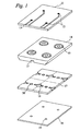
- Fig. 1 shows a simplified exploded perspective top view of a number of distinct ink chambers 22 arranged in a 2 by 2 matrix.
- the apparatus is formed from four layers, which may comprise the same material or thermally compatible materials.
- the interconnect layer 21 has holes 12 formed therein through which electrical connection tracks 13 to a drive circuit are passed.
- the piezoelectric sheet 14 is machined or moulded so as to form a plurality of recesses for defining the ink chambers 22, actuating regions 10 being formed in respective bottom walls thereof.
- the actuating regions 10 are designed so as to allow the piezoelectric sheet 14 to deflect towards nozzle plate 18 without causing cross talk between neighbouring actuating regions.
- Ink channels 15 for allowing ink to flow from a reservoir (not shown) to the ink chambers 22 are formed in the same side of the piezoelectric sheet 14 as the recesses.
- Cut away segments 16 in interposer plate 17 allow ink to flow from the channels 15 into the ink chambers, as shown by means of the arrows in Fig. 2.
- the arrows show ink being circulated from one channel 15, through the chamber 22 and into the adjacent channel. This prevents stagnation and reduces the build up of air within the apparatus.
- the ink can be fed simultaneously from both sides of the actuating region simultaneously.
- the nozzle plate 18 is fixed to the interposer plate 17, and nozzles 19 are provided such that they are situated within the diameter of the orifices 20 of the interposer plate 17.
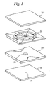
- FIG. 2 The exploded perspective bottom view of the arrangement is shown in Fig. 2. This figure shows more clearly the ink channels 15 and the ink chambers 22 formed in the piezoelectric sheet 14.
- Each ink chamber 22 may be formed with a central projection or depression situated within the ink chamber.
- the projection is shown as being cylindrical, however it will be appreciated that it can also be hemispherical, triangular or any other suitable shape.
- the projection as shown is smaller than the orifice 20 in interposer plate 17 it is, of course, possible that a projection of the same size or larger than the orifice 20 can be suitable provided that the projection is free to move below or within the orifice 20.
- the projection or depression 23 in the ink chamber 22 helps to increase the efficiency of the actuator and improve the control of the drop size and velocity. Additionally, the projection or depression provides a site for applying an electric field during the radial poling of the actuating regions of the piezoelectric sheet 14 during assembly or manufacture.
- Electrodes are formed by sputtering or any other suitable method on both the top surface of the ink chamber 22 and the bottom of the piezoelectric sheet 14. When an electric field is applied between opposing electrodes, an associated actuating region of the piezoelectric sheet that has been poled in a radial direction deflects towards the orifice 20 and ejects ink from the nozzle 19.
- Figs. 3 and 4 illustrate in more detail a single actuating region and ink chamber (details of the interconnect layer 21 having been omitted).
- the simple arrangement of four separate layers allows for easy manufacture using modern moulding methods as well as conventional machining.
- One advantage of manufacture by moulding is that bumps or grooves can be formed on one or more of the plates and sheet with respective hollows or protrusions on the opposite face. This allows for simple but accurate alignment of the respective layers. It is also possible to locate protrusions on the edge surfaces 26 to allow a modular build up of individual or groups of transducers into a larger array of matrices.
- the piezoelectric sheet 14 acting as an insulation barrier.
- the piezoelectric sheet can be joined to the interposer plate 17 and the interconnect plate 21 by means of a conductive adhesive or any other convenient method.
- the nozzles can be formed in situ as well as ex situ depending on the preferred manufacturing method.
- Figs. 1 and 2 show a 2 by 2 matrix a full array assembly would typically consist of a 16 by 16 nozzle array measuring approximately 18 by 18 mm. This gives rise to a dot density of the order 360 dpi.
- the print density can be varied easily in the matrix arrangement simply by specifying a different print density.
- Fig. 5 shows the actuator positions in a 12 by 12 matrix.
- the matrix has total dimensions of 2,54 cm by 2,54 cm (1 inch by 1 inch) and each nozzle is separated from the adjacent nozzle by 0,21 cm (1/12th of an inch).
- a dot density of 144 dpi in both dimensions is formed by indexing the nozzles in both the horizontal and vertical rows by 0.0176 cm (1/144th of an inch).
- FIG. 6 depicts the actuator positions in a 24 by 12 matrix which gives rise to a drop density of 288 dpi in the horizontal direction and 72 dpi in the vertical direction.
- the array is formed from two 24 by 6 modules butted side by side. It is, of course, possible to butt a number of the distinct modules together to form as large an array as required even up to page width.
- the interconnect density does not change significantly depending on the matrix configuration. The same effect of forming the matrix could, of course, be achieved by forming a square or rectangular array and angling the entire head.
- Figs. 7 and 8 are exploded sectional views of the single ink chamber shown in Fig. 3.
- Ink is fed into the ink chamber from either one or both of the sides thereof.
- the actuating region is in the form of a disc of the piezoelectric sheet which is poled radially in the direction of the arrow 27.
- Fig. 8 shows the deflection of the piezoelectric disc as a potential difference is applied across the electrodes 24,25 positioned thereon. As the central projection 23 moves towards the nozzle 19 a droplet is ejected. Once the electric field is removed the piezoelectric disc returns to its original position shown in Fig 7.
- the actuator is capable of emitting ink droplets responsively to applying differential voltage pulses to the electrodes 24, 25. Each such pulse sets up an electric field in the direction normal to the direction of polarisation 27. This develops shear distortion in the piezoelectric disc 14 and causes the disc to deflect in the direction of the electric field, as shown in Fig. 8. This displacement establishes a pressure in the ink chamber. Typically, a pressure of 30-300kPa is applied to operate the ink chamber and this can be obtained with only a small mean deflection since the chamber dimension normal to the plate 14 is small.
- the volume strain or condensation as the pressure wave recedes from the nozzle develops a flow of ink from the nozzle outlet aperture for a period R/c, where c is the effective acoustic velocity of ink in the chamber and R is the radial distance to the walls of the chamber.
- Various methods may be used to alter the drop ejection characteristics from the ink chamber 22.
- One such method is to alter the shape and structure of the ink chamber, for example, by increasing the radius of the ink chamber or altering the profile of the orifice 20.
- the shape of the orifice 20, nozzle 19 and the stiffness of the nozzle plate 18 affect the inertia of ink to be ejected from the chamber.
- variations in the thickness of the piezoelectric disc can give rise to variations in the shear deflection of the disc and alter the drop ejection characteristics.
- Fig. 9 illustrates an embodiment of a method of forming a radially poled piezoelectric disc in a piezoelectric sheet and subsequently depositing electrodes thereon.
- a resist layer 100 is formed, for example, by sputtering, on each side of the piezoelectric sheet.
- the portions of the resist layers formed on the outer side walls 102 and the central portion 104 of the inner bottom wall 106 of each recess are removed by, for example, a grinding, ablation or etching technique, and the remaining portions of the resist layers 100 developed.
- a metallic layer 108 is deposited on each side of the piezoelectric sheet to cover the exposed regions of each recess. As shown in Fig. 9(a), an electric field is applied across the metallic layers to pole radially the actuating regions of the recess so that a poled piezoelectric disc is formed with the directions of polarisation converging towards the centre of the disc.
- the developed resist layers 100 and the metallic layers 108 are removed and second resist layers 110 formed on respective faces of the poled piezoelectric disc, for example, by deposition and subsequent selective removal of the second resist layers 110.
- Electrode 25 forms the common ground electrode for all of the poled piezoelectric discs, and voltages can be selectively applied to individual portions of the electrode layer 24 to activate poled piezoelectric discs as desired.
- piezoelectric discs are poled radially, that is, poled in directions that all converge towards the nozzle axis
- alternative poling arrangements of the piezoelectric discs may also enable radial pressure waves to be generated in the ink chambers by shear mode deflection of the discs upon actuation.
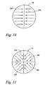
- Figs. 10 and 11 illustrate two such alternative poling arrangements.
- Fig. 10 shows a plan view of piezoelectric disc 14 formed from two identical halves 14a, 14b, each half being poled towards the diameter of the disc 14.
- the piezoelectric disc is formed from four identical quarters 14c... 14f.
- the actuating regions are formed by poled piezoelectric discs.
- the actuating region may take any polygonal shape, for example, triangular, rectangular or hexagonal, with segments of the actuating region being suitably poled for deflection in shear mode upon actuation to develop radial acoustic wave travel in the ink chamber.
- the apparatus is formed of a plurality of laminated plates arranged so as to define an ink chamber 22.
- the actuator forms one side of the chamber and deflects towards a nozzle 19 formed in a nozzle plate 18 which provides the opposite side of the chamber.
- An interconnect layer 21 acts as the substrate and has orifices 12 to allow the tracks 13 to the driver chip to pass through.
- the piezoelectric sheet 14 On the opposite side of the interconnect layer is the piezoelectric sheet 14. Electrodes 24,25 are provided between the interconnect layer and the piezoelectric sheet.
- the piezoelectric sheet is carved, drilled or moulded so as to provide parallel ink channels 15 and a circular depression with a raised central reservation 23.
- the piezoelectric sheet is bonded to the interposer plate or ground electrode which in turn is bonded to the nozzle plate.
- a selected actuator 10 of the piezoelectric sheet 14 deflects in shear mode towards the nozzle plate. This movement provides sufficient energy to eject a droplet from the nozzle.
- a number of short pulses could be applied so as to increase the size of the droplet ejected.
- a number of distinct pressure chambers 22 connected only by the parallel ink channels are arranged in a two dimensional matrix which allows for increased distances between the actuators 10 allowing for less densely packed electrical connections than are required in a linear array.
Landscapes
- Particle Formation And Scattering Control In Inkjet Printers (AREA)
Claims (24)
- Auf Abruf arbeitende Tintenstrahldruckvorrichtung, mit einer Düse (19) auf einer Düsenachse; einer Düsenkammer (22), die sich radial um die Düsenachse erstreckt; einer Tintenzuführungseinrichtung (15, 16), die mit der Düsenkammer (22) in Verbindung steht; und mit einem Betätigungselement (14), das in Richtung der Düsenachse beweglich ist, um das Ausstoßen eines Tintentropfens durch die Düse (19) und die Wiederauffüllung der Tintenkammer mit Tinte zu bewirken;
dadurch gekennzeichnet, dass die Tintenkammer (22) durch eine im Allgemeinen kreisförmige Struktur begrenzt ist, die durch eine Veränderung in der Tintentiefe in Richtung der Düsenachse eine Veränderung in der akustischen Impedanz bereitstellt, die dazu dient, akustische Wellen zu reflektieren, welche radial zur Düsenachse aufgrund der Bewegung des Betätigungselements (14) zur Konvergenz an der Düsenachse in der Tintenkammer (22) wandern, wobei das Betätigungselement dadurch einen Tintentropfenausstoß durch das Wandern akustischer Wellen in der Tintenkammer radial zur Düsenachse bewirkt. - Vorrichtung nach Anspruch 1, bei der die Tintenkammer (22) sich über einen radialen Abstand R von der Düsenachse erstreckt, und bei der das Betätigungselement (14) in der Richtung der Düse (19) zwischen einer ersten und einer zweiten Konfiguration beweglich ist, in einer Zeit, die mindestens der Hälfte der Zeit R/c entspricht, wobei c die Schallgeschwindigkeit durch Tinte in der Tintenkammer (22) ist.
- Vorrichtung nach Anspruch 1 oder 2, bei der das Betätigungselement eine piezoelektrische Betätigungsscheibe (14) umfasst, die der Tintenkammer (22) zugeordnet ist und sich in eine Kuppelkonfiguration und aus dieser heraus bewegen kann, um einen Tintentropfenausstoß zu bewirken, wobei die Vorrichtung ferner Elektroden (24, 25) umfasst, um ein elektrisches Betätigungsfeld auf die piezoelektrische Scheibe (14) aufzubringen.
- Vorrichtung nach Anspruch 3, bei der piezoelektrische Scheibe (14) homogen und so in Relation zum elektrischen Betätigungsfeld gepolt ist, dass sie sich in einem Schermodus bewegt.
- Vorrichtung nach Anspruch 4, bei der das elektrische Feld in Richtung der Düsenachse aufgebracht wird, wobei die piezoelektrische Scheibe (14) radial gepolt ist.
- Vorrichtung nach Anspruch 5, bei der die piezoelektrische Scheibe (14) in Richtungen gepolt ist, die alle zur Düsenachse hin konvergieren.
- Vorrichtung nach Anspruch 5 oder 6, bei der die Elektroden eine Erdungselektrode (24) auf einer Fläche der piezoelektrischen Scheibe (14), welche an die Tintenkammer (22) stößt, und eine andere Elektrode (25) an einer entgegengesetzten Fläche der piezoelektrischen Scheibe umfassen.
- Vorrichtung nach einem der Ansprüche 3 bis 7, bei der die Scheibe (14) mit einem hervorstehenden Bauteil (23) versehen ist, das entlang der Düsenachse hervorsteht.
- Vorrichtung nach einem der Ansprüche 3 bis 7, bei der die Scheibe (14) mit einer Ausnehmung versehen ist, die im Wesentlichen konzentrisch mit der Düse (19) verläuft.
- Vorrichtung nach einem der vorhergehenden Ansprüche, bei der die Tintenzuführungseinrichtung (15, 16) dazu dient, Tinte in die Tintenkammer (22) in einer Richtung radial zur Düsenachse zuzuführen.
- Vorrichtung nach einem der vorhergehenden Ansprüche, bei der die Tintenzuführungseinrichtung (15, 16) dazu dient, Tinte in die Tintenkammer (22) an einer Vielzahl von Stellen zuzuführen, die um den Umfang der Tintenkammer (22) herum angeordnet sind.
- Vorrichtung nach Anspruch 11, bei der die Tintenzuführungseinrichtung (15, 16) dazu dient, Tinte in die Tintenkammer (22) um im Wesentlichen die gesamte Peripherie der Tintenkammer (22) herum zuzuführen.
- Vorrichtung nach einem der vorhergehenden Ansprüche, bei der die im Allgemeinen kreisförmige Struktur einen Tintenring um die Tintenkammer 22 herum definiert, der in Richtung der Düsenachse eine Tiefe aufweist, der sich von der Tiefe der Tintenkammer (22) unterscheidet.
- Vorrichtung nach Anspruch 13, bei der der Ring einen Teil der Tintenzuführungseinrichtung (15, 16) ausbildet.
- Vorrichtung nach einem der vorhergehenden Ansprüche, mit einer Vielzahl von Düsen (19), welche jede eine jeweilige Düsenachse aufweisen, wobei die Düsen parallel und in einer zweidimensionalen Ebenenanordnung vorgesehen sind; mit einer Vielzahl der Tintenkammern (22), von denen jede sich um eine jeweilig Düsenachse herum erstreckt; und mit einem homogenen piezoelektrischen Flächengebilde (14), das eine zweidimensionale Anordnung der Betätigungselemente aufweist, wobei jedes Betätigungselement einer jeweiligen Düsenkammer zugeordnet ist.
- Vorrichtung nach Anspruch 15, sofern dieser von einem der Ansprüche 3 bis 7 abhängt, mit einer Vielzahl der Elektroden (24, 25), mit einer gemeinsamen Erdungselektrode (24) auf einer Fläche des piezoelektrischen Flächengebildes im Anschluss an die Tintenkammem, und mit einer entgegengesetzten Fläche, wobei individuelle Elektroden (25) jeweils den Tintenkammern zugeordnet sind.
- Vorrichtung nach Anspruch 16, bei der die individuellen Elektroden (25) mit elektrischen Impulsaufbringungsvorrichtungen durch jeweilige elektrische Verbindungen verbunden sind, welche auf einer Zwischenverbindungsplatte (21) vorgesehen sind, die mit einer Düsenplatte (18) und dem piezoelektrischen Flächengebilde (14) laminiert ist.
- Vorrichtung nach einem der Ansprüche 15 bis 17, bei der die Düsen in einer Düsenplatte (18) ausgebildet werden, wobei die Düsenplatte (18) mit dem piezoelektrischen Flächengebilde (14) laminiert ist, um die Vielzahl der Düsenkammern (22) bereitzustellen.
- Vorrichtung nach Anspruch 18, bei der die Tintenzuführungsvorrichtung (15, 16) eine Anordnung von Tintenkanälen (15) umfasst, die in dem piezoelektrischen Flächengebilde (14) ausgebildet sind, sowie Tintenübertragungseinrichtungen zum Übertragen von Tinte aus den Tintenkanälen zu den Tintenkammern.
- Vorrichtung nach Anspruch 19, bei der die Tintenübertragungsvorrichtungen eine Anordnung von Ausnehmungen (16) umfassen, welche in einer Zwischenplatte (17) ausgebildet sind, die mit der Düsenplatte (18) und dem piezoelektrischen Flächengebilde (14) laminiert ist.
- Vorrichtung nach Anspruch 20, sofern er vom Anspruch 17 abhängt, bei der die Düsenplatte (18), die Zwischenverbindungsplatte (27) und die Zwischenplatte (17) jeweils ein piezoelektrischen Flächengebilde umfassen.
- Vorrichtung nach Anspruch 20, sofern er vom Anspruch 17 abhängt, bei der die Düsenplatte (18), die Zwischenverbindungsplatte (27) und die Zwischenplatte (17) jeweils ein Flächengebilde aus einem Material umfassen, das thermisch mit dem piezoelektrischen Flächengebilde kompatibel ist.
- Verfahren zum Tintenstrahldrucken mit den folgenden Schritten: Bilden eines planaren Körpers aus Tinte (22) in Verbindung mit einer Düse (19), die eine Düsenachse aufweist, wobei der Körper aus Tinte (22) radial zur Düsenachse erstreckt; dadurch gekennzeichnet, dass in dem Körper der Tinte durch eine Änderung in der Tintentiefe in Richtung der Düsenachse eine Impedanzbegrenzung bereitgestellt wird, die sich am Umfang der Düsenachse erstreckt; und dadurch, dass ein Betätigungselement (14) selektiv in Richtung der Düsenachse so bewegt wird, dass akustische Wellen gebildet werden, die radial zur Düsenachse in der Tintenkammer wandern, wobei die Wellen durch die Impedanzgrenze reflektiert werden und an der Düsenachse konvergieren, wodurch das Ausstoßen eines Tintentröpfchens durch die Düse bewirkt wird.
- Verfahren zum Tintenstrahldrucken gemäß Anspruch 23, mit dem Schritt des Wiederauffüllens des Körpers aus Tinte in Abfolge auf den Tintentröpfchenausstoß, durch das Zuführen von Tinte zu diesem in einer Radialrichtung der Düsenachse.
Applications Claiming Priority (3)
| Application Number | Priority Date | Filing Date | Title |
|---|---|---|---|
| GB9713872 | 1997-07-02 | ||
| GBGB9713872.1A GB9713872D0 (en) | 1997-07-02 | 1997-07-02 | Droplet deposition apparatus |
| PCT/GB1998/001955 WO1999001284A1 (en) | 1997-07-02 | 1998-07-02 | Drop on demand ink jet printing apparatus |
Publications (2)
| Publication Number | Publication Date |
|---|---|
| EP0993376A1 EP0993376A1 (de) | 2000-04-19 |
| EP0993376B1 true EP0993376B1 (de) | 2003-10-01 |
Family
ID=10815194
Family Applications (1)
| Application Number | Title | Priority Date | Filing Date |
|---|---|---|---|
| EP98932354A Expired - Lifetime EP0993376B1 (de) | 1997-07-02 | 1998-07-02 | Auf abruf arbeitende tintenstrahldruckvorrichtung |
Country Status (11)
| Country | Link |
|---|---|
| US (1) | US6422690B1 (de) |
| EP (1) | EP0993376B1 (de) |
| JP (1) | JP3694533B2 (de) |
| KR (1) | KR100602933B1 (de) |
| CN (1) | CN1160195C (de) |
| AU (1) | AU739819B2 (de) |
| BR (1) | BR9810389A (de) |
| CA (1) | CA2294174A1 (de) |
| DE (1) | DE69818666T2 (de) |
| GB (1) | GB9713872D0 (de) |
| WO (1) | WO1999001284A1 (de) |
Families Citing this family (29)
| Publication number | Priority date | Publication date | Assignee | Title |
|---|---|---|---|---|
| GB9820755D0 (en) | 1998-09-23 | 1998-11-18 | Xaar Technology Ltd | Drop on demand ink jet printing apparatus |
| JP3832338B2 (ja) * | 2001-12-25 | 2006-10-11 | 松下電工株式会社 | 電歪ポリマーアクチュエータ |
| GB0204010D0 (en) | 2002-02-20 | 2002-04-03 | Xaar Technology Ltd | Droplet deposition apparatus |
| GB0204009D0 (en) | 2002-02-20 | 2002-04-03 | Xaar Technology Ltd | Actuation device and use thereof in droplet deposition |
| JP3632701B2 (ja) * | 2002-08-20 | 2005-03-23 | セイコーエプソン株式会社 | 液体噴射ヘッドおよびその製造方法 |
| US6719405B1 (en) | 2003-03-25 | 2004-04-13 | Lexmark International, Inc. | Inkjet printhead having convex wall bubble chamber |
| US8251471B2 (en) * | 2003-08-18 | 2012-08-28 | Fujifilm Dimatix, Inc. | Individual jet voltage trimming circuitry |
| CN100579779C (zh) * | 2004-03-31 | 2010-01-13 | 京瓷株式会社 | 液体喷出装置 |
| US8085428B2 (en) | 2004-10-15 | 2011-12-27 | Fujifilm Dimatix, Inc. | Print systems and techniques |
| US7907298B2 (en) * | 2004-10-15 | 2011-03-15 | Fujifilm Dimatix, Inc. | Data pump for printing |
| US8068245B2 (en) * | 2004-10-15 | 2011-11-29 | Fujifilm Dimatix, Inc. | Printing device communication protocol |
| US7911625B2 (en) * | 2004-10-15 | 2011-03-22 | Fujifilm Dimatrix, Inc. | Printing system software architecture |
| US7722147B2 (en) * | 2004-10-15 | 2010-05-25 | Fujifilm Dimatix, Inc. | Printing system architecture |
| US8199342B2 (en) * | 2004-10-29 | 2012-06-12 | Fujifilm Dimatix, Inc. | Tailoring image data packets to properties of print heads |
| US7234788B2 (en) * | 2004-11-03 | 2007-06-26 | Dimatix, Inc. | Individual voltage trimming with waveforms |
| US7556327B2 (en) * | 2004-11-05 | 2009-07-07 | Fujifilm Dimatix, Inc. | Charge leakage prevention for inkjet printing |
| CN100349741C (zh) * | 2004-12-30 | 2007-11-21 | 财团法人工业技术研究院 | 具有膜片的压电式微液滴喷射装置 |
| JP4362629B2 (ja) * | 2005-01-31 | 2009-11-11 | 独立行政法人産業技術総合研究所 | 一括転写型インクジェット用ノズルプレートの製造方法 |
| CN100391741C (zh) * | 2005-08-18 | 2008-06-04 | 财团法人工业技术研究院 | 喷孔片 |
| US7997709B2 (en) * | 2006-06-20 | 2011-08-16 | Eastman Kodak Company | Drop on demand print head with fluid stagnation point at nozzle opening |
| CN101342520B (zh) * | 2007-07-10 | 2011-08-03 | 研能科技股份有限公司 | 微液滴喷射结构 |
| WO2009149163A2 (en) | 2008-06-06 | 2009-12-10 | Fujifilm Dimatix, Inc. | Sensing objects for printing |
| JP4720917B2 (ja) * | 2009-03-02 | 2011-07-13 | ブラザー工業株式会社 | 液体吐出ヘッド及びこれを含む記録装置の製造方法、並びに、液体吐出ヘッド及び記録装置 |
| KR101569837B1 (ko) | 2009-12-09 | 2015-11-30 | 삼성전자주식회사 | 잉크젯 프린팅 장치 및 그 구동 방법 |
| KR102022392B1 (ko) * | 2012-12-11 | 2019-11-05 | 삼성디스플레이 주식회사 | 노즐프린터 |
| GB2516845A (en) * | 2013-07-31 | 2015-02-11 | Ingegneria Ceramica S R L | An Improved Actuator and Method of Driving Thereof |
| EP3490801B1 (de) | 2016-07-27 | 2021-06-30 | President and Fellows of Harvard College | Vorrichtung und verfahren für akustophoretisches drucken |
| US11065868B2 (en) * | 2017-07-12 | 2021-07-20 | Mycronic AB | Jetting devices with acoustic transducers and methods of controlling same |
| KR20250167146A (ko) | 2019-03-29 | 2025-11-28 | 프레지던트 앤드 펠로우즈 오브 하바드 칼리지 | 음향영동 인쇄를 위한 서브파장 공진기 |
Family Cites Families (21)
| Publication number | Priority date | Publication date | Assignee | Title |
|---|---|---|---|---|
| US3946398A (en) | 1970-06-29 | 1976-03-23 | Silonics, Inc. | Method and apparatus for recording with writing fluids and drop projection means therefor |
| SE349676B (de) | 1971-01-11 | 1972-10-02 | N Stemme | |
| DE2349555C2 (de) | 1973-04-25 | 1983-04-07 | Siemens AG, 1000 Berlin und 8000 München | Druckkopf für Farbflüssigkeits-Spritzdrucker und dergleichen |
| DE2927488A1 (de) | 1979-07-07 | 1981-01-22 | Philips Patentverwaltung | Tintenstrahldrucker |
| US4353078A (en) | 1979-09-24 | 1982-10-05 | International Business Machines Corporation | Ink jet print head having dynamic impedance adjustment |
| US4383264A (en) | 1980-06-18 | 1983-05-10 | Exxon Research And Engineering Co. | Demand drop forming device with interacting transducer and orifice combination |
| JPS57133081A (en) * | 1981-02-13 | 1982-08-17 | Hitachi Ltd | Ink particle making device |
| JPS58168573A (ja) * | 1982-03-31 | 1983-10-04 | Fujitsu Ltd | インクジエツトプリントヘツドの駆動方法 |
| DE3342844A1 (de) | 1983-11-26 | 1985-06-05 | Philips Patentverwaltung Gmbh, 2000 Hamburg | Mikroplanarer tintenstrahldruckkopf |
| DE3712891A1 (de) * | 1987-04-15 | 1988-11-03 | Siemens Ag | Planartintendruckkopf im dual-inline-gehaeuse |
| WO1988010192A1 (fr) * | 1987-06-25 | 1988-12-29 | Siemens Aktiengesellschaft | Tete d'impression a l'encre avec chambres de pression a alimentation tangentielle d'encre |
| JP2806386B2 (ja) * | 1988-02-16 | 1998-09-30 | 富士電機株式会社 | インクジェット記録ヘッド |
| US4825227A (en) * | 1988-02-29 | 1989-04-25 | Spectra, Inc. | Shear mode transducer for ink jet systems |
| US4998120A (en) | 1988-04-06 | 1991-03-05 | Seiko Epson Corporation | Hot melt ink jet printing apparatus |
| DE3814150A1 (de) | 1988-04-27 | 1989-11-09 | Draegerwerk Ag | Ventilanordnung aus mikrostrukturierten komponenten |
| US5087930A (en) * | 1989-11-01 | 1992-02-11 | Tektronix, Inc. | Drop-on-demand ink jet print head |
| JPH0890769A (ja) | 1994-09-27 | 1996-04-09 | Sharp Corp | ひだ付きダイアフラム型インクジェットヘッド |
| US5828394A (en) * | 1995-09-20 | 1998-10-27 | The Board Of Trustees Of The Leland Stanford Junior University | Fluid drop ejector and method |
| JPH0985946A (ja) * | 1995-09-25 | 1997-03-31 | Sharp Corp | インクジェットヘッド及びその製造方法 |
| JPH09104109A (ja) * | 1995-10-12 | 1997-04-22 | Sharp Corp | インクジェットヘッドおよびその製造方法 |
| US5757400A (en) | 1996-02-01 | 1998-05-26 | Spectra, Inc. | High resolution matrix ink jet arrangement |
-
1997
- 1997-07-02 GB GBGB9713872.1A patent/GB9713872D0/en active Pending
-
1998
- 1998-07-02 WO PCT/GB1998/001955 patent/WO1999001284A1/en not_active Ceased
- 1998-07-02 CN CNB988063786A patent/CN1160195C/zh not_active Expired - Fee Related
- 1998-07-02 CA CA002294174A patent/CA2294174A1/en not_active Abandoned
- 1998-07-02 KR KR1019997012511A patent/KR100602933B1/ko not_active Expired - Fee Related
- 1998-07-02 EP EP98932354A patent/EP0993376B1/de not_active Expired - Lifetime
- 1998-07-02 AU AU82292/98A patent/AU739819B2/en not_active Ceased
- 1998-07-02 BR BR9810389-0A patent/BR9810389A/pt not_active IP Right Cessation
- 1998-07-02 DE DE69818666T patent/DE69818666T2/de not_active Expired - Fee Related
- 1998-07-02 JP JP50667399A patent/JP3694533B2/ja not_active Expired - Fee Related
-
1999
- 1999-12-30 US US09/475,816 patent/US6422690B1/en not_active Expired - Lifetime
Also Published As
| Publication number | Publication date |
|---|---|
| KR100602933B1 (ko) | 2006-07-19 |
| WO1999001284A1 (en) | 1999-01-14 |
| DE69818666T2 (de) | 2004-08-19 |
| DE69818666D1 (de) | 2003-11-06 |
| BR9810389A (pt) | 2000-09-05 |
| CN1264338A (zh) | 2000-08-23 |
| CA2294174A1 (en) | 1999-01-14 |
| US6422690B1 (en) | 2002-07-23 |
| CN1160195C (zh) | 2004-08-04 |
| AU8229298A (en) | 1999-01-25 |
| AU739819B2 (en) | 2001-10-18 |
| KR20010014354A (ko) | 2001-02-26 |
| EP0993376A1 (de) | 2000-04-19 |
| GB9713872D0 (en) | 1997-09-03 |
| JP3694533B2 (ja) | 2005-09-14 |
| JP2001502624A (ja) | 2001-02-27 |
Similar Documents
| Publication | Publication Date | Title |
|---|---|---|
| US6422690B1 (en) | Drop on demand ink jet printing apparatus, method of ink jet printing, and method of manufacturing an ink jet printing apparatus | |
| EP1115577B1 (de) | Auf Abruf arbeitende Tintenstrahldruckvorrichtung, Druckverfahren und Herstellungsverfahren | |
| EP1011977B1 (de) | Tröpfchen-niederschlagvorrichtung | |
| US7625075B2 (en) | Actuator | |
| EP1815991B1 (de) | Piezoelektrischer Tintenstrahldruckkopf | |
| US4752789A (en) | Multi-layer transducer array for an ink jet apparatus | |
| JP2009160798A (ja) | 液滴吐出ヘッド | |
| US7073894B2 (en) | Ink jet printer head | |
| JP2006326972A (ja) | インクジェット記録ヘッド用基板および該基板を用いるインクジェット記録ヘッド | |
| JP4810908B2 (ja) | インクジェットヘッド | |
| JPH04182138A (ja) | インクジェットヘッド及びその製造方法 | |
| US5410340A (en) | Off center heaters for thermal ink jet printheads | |
| JP2638780B2 (ja) | インクジェット記録ヘッド | |
| JPH04223175A (ja) | インクジェットプリントヘッド | |
| US5955022A (en) | Process of making an orifice plate for a page-wide ink jet printhead | |
| JPH0825627A (ja) | インクジェットヘッドおよびその製造方法 | |
| JPH09511465A (ja) | インクジェット記録装置 | |
| JPH0410939A (ja) | インクジェット記録装置 | |
| JPWO1995010416A1 (ja) | インクジェットヘッドとその製造方法及びその駆動方法 | |
| JPH03180351A (ja) | インクジェットヘッド | |
| JP2004168054A (ja) | インクジェット型プリントヘッド | |
| JPH1134317A (ja) | インクジェット記録ヘッド |
Legal Events
| Date | Code | Title | Description |
|---|---|---|---|
| PUAI | Public reference made under article 153(3) epc to a published international application that has entered the european phase |
Free format text: ORIGINAL CODE: 0009012 |
|
| 17P | Request for examination filed |
Effective date: 20000202 |
|
| AK | Designated contracting states |
Kind code of ref document: A1 Designated state(s): CH DE FR GB IE IT LI NL SE |
|
| 17Q | First examination report despatched |
Effective date: 20010329 |
|
| GRAH | Despatch of communication of intention to grant a patent |
Free format text: ORIGINAL CODE: EPIDOS IGRA |
|
| GRAH | Despatch of communication of intention to grant a patent |
Free format text: ORIGINAL CODE: EPIDOS IGRA |
|
| GRAA | (expected) grant |
Free format text: ORIGINAL CODE: 0009210 |
|
| AK | Designated contracting states |
Kind code of ref document: B1 Designated state(s): CH DE FR GB IE IT LI NL SE |
|
| PG25 | Lapsed in a contracting state [announced via postgrant information from national office to epo] |
Ref country code: NL Free format text: LAPSE BECAUSE OF FAILURE TO SUBMIT A TRANSLATION OF THE DESCRIPTION OR TO PAY THE FEE WITHIN THE PRESCRIBED TIME-LIMIT Effective date: 20031001 Ref country code: LI Free format text: LAPSE BECAUSE OF FAILURE TO SUBMIT A TRANSLATION OF THE DESCRIPTION OR TO PAY THE FEE WITHIN THE PRESCRIBED TIME-LIMIT Effective date: 20031001 Ref country code: CH Free format text: LAPSE BECAUSE OF FAILURE TO SUBMIT A TRANSLATION OF THE DESCRIPTION OR TO PAY THE FEE WITHIN THE PRESCRIBED TIME-LIMIT Effective date: 20031001 |
|
| REG | Reference to a national code |
Ref country code: GB Ref legal event code: FG4D |
|
| REG | Reference to a national code |
Ref country code: CH Ref legal event code: EP |
|
| REG | Reference to a national code |
Ref country code: IE Ref legal event code: FG4D |
|
| REF | Corresponds to: |
Ref document number: 69818666 Country of ref document: DE Date of ref document: 20031106 Kind code of ref document: P |
|
| PG25 | Lapsed in a contracting state [announced via postgrant information from national office to epo] |
Ref country code: SE Free format text: LAPSE BECAUSE OF FAILURE TO SUBMIT A TRANSLATION OF THE DESCRIPTION OR TO PAY THE FEE WITHIN THE PRESCRIBED TIME-LIMIT Effective date: 20040101 |
|
| NLV1 | Nl: lapsed or annulled due to failure to fulfill the requirements of art. 29p and 29m of the patents act | ||
| REG | Reference to a national code |
Ref country code: CH Ref legal event code: PL |
|
| ET | Fr: translation filed | ||
| PG25 | Lapsed in a contracting state [announced via postgrant information from national office to epo] |
Ref country code: IE Free format text: LAPSE BECAUSE OF NON-PAYMENT OF DUE FEES Effective date: 20040702 |
|
| PLBE | No opposition filed within time limit |
Free format text: ORIGINAL CODE: 0009261 |
|
| STAA | Information on the status of an ep patent application or granted ep patent |
Free format text: STATUS: NO OPPOSITION FILED WITHIN TIME LIMIT |
|
| 26N | No opposition filed |
Effective date: 20040702 |
|
| REG | Reference to a national code |
Ref country code: IE Ref legal event code: MM4A |
|
| PGFP | Annual fee paid to national office [announced via postgrant information from national office to epo] |
Ref country code: DE Payment date: 20080711 Year of fee payment: 11 |
|
| PGFP | Annual fee paid to national office [announced via postgrant information from national office to epo] |
Ref country code: IT Payment date: 20080729 Year of fee payment: 11 Ref country code: FR Payment date: 20080718 Year of fee payment: 11 |
|
| PGFP | Annual fee paid to national office [announced via postgrant information from national office to epo] |
Ref country code: GB Payment date: 20090701 Year of fee payment: 12 |
|
| REG | Reference to a national code |
Ref country code: FR Ref legal event code: ST Effective date: 20100331 |
|
| PG25 | Lapsed in a contracting state [announced via postgrant information from national office to epo] |
Ref country code: FR Free format text: LAPSE BECAUSE OF NON-PAYMENT OF DUE FEES Effective date: 20090731 |
|
| PG25 | Lapsed in a contracting state [announced via postgrant information from national office to epo] |
Ref country code: DE Free format text: LAPSE BECAUSE OF NON-PAYMENT OF DUE FEES Effective date: 20100202 |
|
| GBPC | Gb: european patent ceased through non-payment of renewal fee |
Effective date: 20100702 |
|
| PG25 | Lapsed in a contracting state [announced via postgrant information from national office to epo] |
Ref country code: IT Free format text: LAPSE BECAUSE OF NON-PAYMENT OF DUE FEES Effective date: 20090702 |
|
| PG25 | Lapsed in a contracting state [announced via postgrant information from national office to epo] |
Ref country code: GB Free format text: LAPSE BECAUSE OF NON-PAYMENT OF DUE FEES Effective date: 20100702 |