EP0993071B1 - Member for assembling radio wave absorber and method of producing radio wave absorber - Google Patents
Member for assembling radio wave absorber and method of producing radio wave absorber Download PDFInfo
- Publication number
- EP0993071B1 EP0993071B1 EP99119700A EP99119700A EP0993071B1 EP 0993071 B1 EP0993071 B1 EP 0993071B1 EP 99119700 A EP99119700 A EP 99119700A EP 99119700 A EP99119700 A EP 99119700A EP 0993071 B1 EP0993071 B1 EP 0993071B1
- Authority
- EP
- European Patent Office
- Prior art keywords
- radio wave
- wave absorber
- incombustible
- base material
- base
- Prior art date
- Legal status (The legal status is an assumption and is not a legal conclusion. Google has not performed a legal analysis and makes no representation as to the accuracy of the status listed.)
- Expired - Lifetime
Links
Images


Classifications
-
- H—ELECTRICITY
- H05—ELECTRIC TECHNIQUES NOT OTHERWISE PROVIDED FOR
- H05K—PRINTED CIRCUITS; CASINGS OR CONSTRUCTIONAL DETAILS OF ELECTRIC APPARATUS; MANUFACTURE OF ASSEMBLAGES OF ELECTRICAL COMPONENTS
- H05K9/00—Screening of apparatus or components against electric or magnetic fields
- H05K9/0001—Rooms or chambers
- H05K9/0003—Shielded walls, floors, ceilings, e.g. wallpaper, wall panel, electro-conductive plaster, concrete, cement, mortar
-
- H—ELECTRICITY
- H01—ELECTRIC ELEMENTS
- H01Q—ANTENNAS, i.e. RADIO AERIALS
- H01Q17/00—Devices for absorbing waves radiated from an antenna; Combinations of such devices with active antenna elements or systems
-
- H—ELECTRICITY
- H01—ELECTRIC ELEMENTS
- H01Q—ANTENNAS, i.e. RADIO AERIALS
- H01Q17/00—Devices for absorbing waves radiated from an antenna; Combinations of such devices with active antenna elements or systems
- H01Q17/008—Devices for absorbing waves radiated from an antenna; Combinations of such devices with active antenna elements or systems with a particular shape
-
- Y—GENERAL TAGGING OF NEW TECHNOLOGICAL DEVELOPMENTS; GENERAL TAGGING OF CROSS-SECTIONAL TECHNOLOGIES SPANNING OVER SEVERAL SECTIONS OF THE IPC; TECHNICAL SUBJECTS COVERED BY FORMER USPC CROSS-REFERENCE ART COLLECTIONS [XRACs] AND DIGESTS
- Y10—TECHNICAL SUBJECTS COVERED BY FORMER USPC
- Y10T—TECHNICAL SUBJECTS COVERED BY FORMER US CLASSIFICATION
- Y10T428/00—Stock material or miscellaneous articles
- Y10T428/24—Structurally defined web or sheet [e.g., overall dimension, etc.]
- Y10T428/24149—Honeycomb-like
-
- Y—GENERAL TAGGING OF NEW TECHNOLOGICAL DEVELOPMENTS; GENERAL TAGGING OF CROSS-SECTIONAL TECHNOLOGIES SPANNING OVER SEVERAL SECTIONS OF THE IPC; TECHNICAL SUBJECTS COVERED BY FORMER USPC CROSS-REFERENCE ART COLLECTIONS [XRACs] AND DIGESTS
- Y10—TECHNICAL SUBJECTS COVERED BY FORMER USPC
- Y10T—TECHNICAL SUBJECTS COVERED BY FORMER US CLASSIFICATION
- Y10T428/00—Stock material or miscellaneous articles
- Y10T428/24—Structurally defined web or sheet [e.g., overall dimension, etc.]
- Y10T428/2419—Fold at edge
Description
- The present invention relates to a radio wave absorber used in a radio wave anechoic room.
- In recent years, use of electric waves has been spread rapidly in the field of mobile communication to realize a higher-grade information oriented society. On the other hand, various electronic appliances have been popularized with the reformative advance of today's microelectronics technology. With the advance of such information communication technology, however, the influence of unnecessary electromagnetic wave noise, or the like, on apparatuses relevant to precision machinery has become a subject of discussion.
- A radio wave anechoic room (radio wave dark room) having no electromagnetic wave reflection is generally used for measurement of electromagnetic wave noise. A radio wave absorber is disposed in an inner wall of such a radio wave anechoic room. Examples of the background-art radio wave absorber used in the radio wave anechoic room include radio wave absorbers made from organic materials such as foamed styrol, foamed styrene, foamed urethane, etc., mixed with carbon black, or the like, to obtain electrical conductivity. Further, the radio wave absorber is used as a stereostructure shaped into a quadrangular pyramid, a triangular prism or a wedge. For example, the radio wave absorber having such a stereostructure is generally produced by: preparatorily foaming not-yet-foamed polystyrol grains into a ball shape having a diameter of the order of millimeters; coating a surface of the ball with powder of an electrically conductive material such as carbon black, or the like; putting the ball in a desired mold; and then heating the mold to thereby secondarily foam the polystyrol grains.
- On the other hand, there is proposed a method of producing a desired-shape radio wave absorber, comprising the steps of: locally heating a predetermined folding portion of an assembly member made from a radio wave-absorbent thermoplastic synthetic resin to thereby soften the folding portion; and then folding the assembly member at the folding portion (
Japanese Patent No. 2760578 - The quadrangular pyramid-, triangular prism- or wedge-shaped radio wave absorber produced by a method of thermally foaming an organic material such as polystyrol, polystyrene, polyurethane, or the like, however, has a problem that not only the radio wave absorber is bulky but also the radio wave absorber is easy to break by contact, or the like, when it is carried for construction of a radio wave anechoic room.
- Further, in the producing method according to
Japanese Patent No. 2760578 -
EP 0 689 262 discloses wave absorber members having a radio wave absorber composition laminated onto a nonflammable light weight sheet. - The present invention is designed upon the aforementioned actual circumstances. The object of the present invention is to provide a method in which a desired-shape radio wave absorber excellent in working efficiency for construction of a radio wave anechoic room and having incombustible characteristic can be produced easily, and a member which can be used in the method for assembling a radio wave absorber.
In order to achieve the above object, according to the present invention, the member for assembling a radio wave absorber is configured according to the features of claim 1.
Further, the member for assembling a radio wave absorber according to the invention is configured so that the base material has folding groove portions in regions in which the incombustible materials are not fixed.
Further, the member for assembling a radio wave absorber according to the invention is configured so that the base material is constituted by a connected body which is formed by joining a plurality of base material parts to one another by foldable joint members in regions in which the incombustible materials are not fixed.
Further, the member for assembling a radio wave absorber according to the invention is configured so that each of the incombustible materials constituted by the honey-comb structure is formed by making incombustible sheets from a slurry containing a water-containing inorganic compound and an electrically conductive material.
Further, the member for assembling a radio wave absorber according to the invention is configured so that each of the incombustible materials has a surface constituted by an electrically conductive layer containing an electrically conductive material.
The method of producing a radio wave absorber according to the present invention is configured according to the features ofclaims 6 and 7 . - Further, the method of producing a radio wave absorber according to the invention is configured so that the shape of the radio wave absorber is any one of shapes including a quadrangular pyramid shape, a triangular prism shape, and a wedge shape.
- Further, the method of producing a radio wave absorber according to the invention is configured so that folding groove portions are formed in regions of the base material free from the incombustible materials in advance so that the base material is folded in the groove portions.
- In the present invention, the member for assembling a radio wave absorber is not bulky and easy to handle because it has a flat shape. Further, when a desired structure is produced by folding the incombustible base material of the radio wave absorber-assembling member or when a desired structure is produced by folding the radio wave absorber-assembling member by the bonding member, a radio wave absorber having the radio wave-absorbent incombustible material fixed to a predetermined region of the structure can be obtained.
-
- Figs. 1A and 1B are perspective views showing a radio wave absorber-assembling member and a radio wave absorber produced by use of this member, as an embodiment of the present invention;
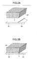
- Figs. 2A and 2B are partly perspective views for explaining fixation of a incombustible material onto a incombustible base material in which a groove portion is provided in advance, Fig. 2A shows a state before the fixation, Fig. 2B shows a state after the fixation;
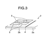
- Fig. 3 is a perspective view showing another example of the incombustible base material which constitutes a radio wave absorber-assembling member according to the present invention;
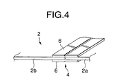
- Fig. 4 is a perspective view showing an example of formation of a folding groove portion in the incombustible base material;
- Figs. 5A to 5D are views showing examples of bonding end portions of the incombustible base material in a producing method according to the present invention;
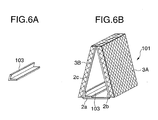
- Figs. 6A and 6B are views for explaining reinforcement of the radio wave absorber assembled in the producing method according to the present invention, Fig. 6A is a perspective view of a reinforcing member, Fig. 6B is a perspective view showing a state in which the radio wave absorber is reinforced by such reinforcing members;
- Figs. 7A and 7B are views for explaining reinforcement of the radio wave absorber assembled in the producing method according to the present invention, Fig. 7A is a perspective view of a reinforcing member, Fig. 7B is a perspective view showing a state in which the radio wave absorber is reinforced by such reinforcing members;
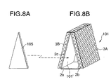
- Figs. 8A and 8B are views for explaining reinforcement of the radio wave absorber assembled in the producing method according to the present invention, Fig. 8A is a perspective view of a reinforcing member, Fig. 8B is a perspective view showing a state in which the radio wave absorber is reinforced by such a reinforcing member;
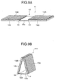
- Figs. 9A and 9B are perspective views showing a radio wave absorber-assembling member and a radio wave absorber produced by use of this member, as another embodiment of the present invention, Fig. 9A shows the radio wave absorber-assembling member, Fig. 9B shows the radio wave absorber.
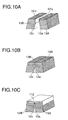
- Figs. 10A to 10C are views showing an example of bonding end portions of the base material in the producing method according to the present invention;
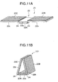
- Figs. 11A and 11B are perspective views showing a radio wave absorber-assembling member and a radio wave absorber produced by use of this member, as a further embodiment of the present invention, Fig. 11A shows the radio wave absorber-assembling member, Fig. 11B shows the radio wave absorber;
- Figs. 12A and 12B are perspective views showing a radio wave absorber-assembling member and a radio wave absorber produced by use of this member, as a still further embodiment of the present invention, Fig. 12A shows the radio wave absorber-assembling member, Fig. 12B shows the radio wave absorber;
- Figs. 13A to 13C are views showing a radio wave absorber-assembling member and a radio wave absorber produced by use of this member, as another embodiment of the present invention, Fig. 13A is a perspective view showing the radio wave absorber-assembling member, Fig. 13B is a sectional view taken along the line A-A in Fig. 13A, Fig. 13C is a perspective view showing the radio wave absorber;
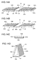
- Figs. 14A to 14D are views showing a radio wave absorber-assembling a radio wave absorber produced by use of this member, as a further embodiment of the present invention, Figs. 14A and 14B are perspective views showing the radio wave absorber-assembling member, Fig. 14C is a sectional view taken along the line B-B in Fig. 14B, Fig. 14D is a perspective view showing the radio wave absorber;
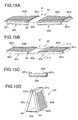
- Figs. 15A to 15D are views showing a radio wave absorber-assembling member and a radio wave absorber produced by use of this member, as a still further embodiment of the present invention, Figs. 15A and 15B are perspective views showing the radio wave absorber-assembling member, Fig. 15C is a sectional view taken along the line C-C in Fig. 15B, Fig. 15D is a perspective view showing the radio wave absorber;
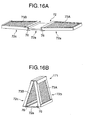
- Figs. 16A and 16B are perspective views showing a radio wave absorber-assembling member and a radio wave absorber produced by use of this member, as another embodiment of the present invention, Fig. 16A shows the radio wave absorber-assembling member, Fig. 16B shows the radio wave absorber;
- Figs. 17A to 17C are views for explaining the structure of the radio wave absorber-assembling member shown in Fig. 16A; and
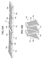
- Figs. 18A and 18B are perspective views showing radio wave absorber-assembling member and a radio wave absorber produced by use of this member, as a further embodiment of the present invention, Fig. 18A shows the radio wave absorber-assembling member, Fig. 18B shows the radio wave absorber.
- Embodiments of the present invention will be described below.
- Figs. 1A and 1B are perspective views showing a member for assembling a radio wave absorber according to the present invention and a radio wave absorber produced by use of the member, as an embodiment of the present invention. In Fig. 1A, the member 1 for assembling a radio wave absorber has a
incombustible base material 2, and radio wave-absorbentincombustible materials base material 2. The terminology "incombustible" used in the present invention means a property of a material which can pass the constructional material testing method (Notification No. 1828 of the Ministry of Construction) in which the material is judged as an incombustible one if the rise of the furnace temperature is lower than 50°C when the material is left in a furnace at 750°C for 20 minutes. The terminology "radio wave absorbent" means the property of a material which has a value of reflectivity not larger than about -20 dB. - The
base material 2 has aregion 2a in which no incombustible material is provided, andregions incombustible materials groove portions 4 are provided in the boundary between theregions regions base material 2 is folded at theaforementioned groove portions 4, a wedge-shaped structure can be assembled. Figs. 2A and 2B are partly perspective views for explaining fixation of theincombustible material 3A onto thebase material 2. Thebase material 2 having thegroove portion 4 provided in advance is prepared as shown in Fig. 2A. Theincombustible material 3A is fixed onto theregion 2b of thebase material 2 so that an end portion of theincombustible material 3A coincides with an end portion of the groove portion 4 (Fig. 2B). An adhesive agent, such as Portland cement, gypsum, or the like, which is hardened by hydration or an inorganic adhesive agent such as phosphoric acid salt, silica sol, a water-glass composition, or the like, can be used for fixation of the incombustible material onto the base material. - Examples of the
incombustible base material 2 as one of constituent parts of the radio wave absorber-assembling member 1 include: a molded body made from ceramic fiber nonwoven fabric; a molded body made from glass fiber nonwoven fabric; a calcium silicate board; a calcium carbonate foam board; a sheet of incombustible paper; a pressure-molded body of a laminate formed by bonding sheets of incombustible paper to one another through an inorganic adhesive agent; and so on. Of these, a pressure-molded body of a laminate formed by bonding sheets of incombustible paper to one another through an inorganic adhesive agent is particularly preferable in terms of facilitation of formation of thegroove portion 4 at a folding position, facilitation of folding work, durability of thebase material 2 in the folding work, and so on. - Further, in the present invention, an opening portion may be provided in the
incombustible base material 2 for the purposes of reduction of weight and improvement of heat radiation so long as the mechanical strength of thebase material 2 becomes no issue in practical use. Fig. 3 is a partly perspective view showing an example of such aincombustible base material 2 in which a plurality of openingportions 5 are provided in theregion 2b to which theincombustible material 3A is fixed. The shape, position, number, etc. of openingportions 5 can be set suitably in consideration of the mechanical strength of thebase material 2. - Any method, such as a method of pressing a sectionally-V-shaped mold, a method of cutting the incombustible base material by a rotary knife, or the like, may be used for formation of the aforementioned
folding groove portion 4 in theincombustible base material 2. As for the number ofgroove portions 4 to be formed, a line may be formed in a place as shown in Fig. 4 or a plurality of parallel lines may be formed in a place. Alternatively, as shown in Fig. 4, groovedjoint members 6 may be fixed to a butt-joint portion between base material parts (regions) 2a and 2b which are constituent parts of thebase material 2. A material formed by molding flame-resistant fiber, glass fiber, or the like, by use of an inorganic adhesive agent can be used as each of the groovedbonding members 6. Although Fig. 4 shows the case where a pair of groovedjoint members 6 are bonded to opposite surfaces of thebase material 2 respectively, a groovedjoint member 6 may be bonded to only one surface in accordance with the position of fixation of the incombustible material, and so on. - The thickness of the aforementioned
incombustible base material 2 can be set to be in a range of from about 0.3 to about 10 mm and the depth of thefolding groove portion 4 can be set to be in a range of from about 0.1 to about 6 mm. Preferably, the thickness of theincombustible base material 2 is in a range of from about 0.5 to about 3 mm and the depth of thefolding groove portion 4 is in a range of from about 0.1 to about 1 mm. - The radio wave-absorbent
incombustible materials incombustible materials base material 2 have substantially the same shapes as those of theregions base material 2. Examples of a material which can be used as each of theincombustible materials Japanese Patent No. 2743227 JP-A-9-307268 JP-A-8-67544 - Carbon black, graphite, carbon fiber, or the like, can be used as the aforementioned electrically conductive material. Silastic balloons, silica balloons, glass beads, perlite, alumina-silica balloons, or the like, can be used as the closed-cell inorganic grains. Further, examples of the inorganic adhesive agent which can be used, include: adhesive agents, such as Portland cement, gypsum, etc., which is hardened by hydration; and inorganic adhesive agents such as phosphoric acid salt, silica sol, a water-glass composition, etc.; and so on. Especially, a water-glass composition can be used preferably because it is inexpensive and high in cementing characteristic. Water-glass is an aqueous solution containing alkaline metal silicate as a main component. Especially, sodium silicate is preferable because it is inexpensive and easily available as an article standardized according to JIS. Further, a mixture of water-glass of sodium silicate and water-glass of lithium silicate may be used.
- A honey-comb structure as each of the
incombustible materials - The thickness of each of the
incombustible materials - In the present invention, each of the
incombustible materials - In the present invention, an inorganic coating film made from water-glass, or the like, may be further formed on the aforementioned electrically conductive layer. By the provision of the inorganic coating film, not only both tensile strength and compressive strength of an incombustible material, especially of a honey-comb structure, can be enhanced but also the spread state of the honey-comb structure can be held more stably.
- The method of producing a radio wave absorber according to the present invention has the steps of: folding the aforementioned radio wave absorber-assembling member 1 at groove portions 4 (regions to which the radio wave-absorbent
incombustible materials base material 2 so as to assemble a wedge-shaped structure having theincombustible materials region 2a of thebase material 2 as its base; and bonding an end portion of theregion 2a of thebase material 2 to an end portion of theregion 2c of thebase material 2 to thereby obtain a radio wave absorber 101 (Fig. 1B). - With respect to the folding of the
base material 2 in regions in which the radio wave-absorbentincombustible materials base material 2 can be folded in the case where nogroove portion 4 is formed. - Bonding of an end portion of the
region 2a of thebase material 2 to an end portion of theregion 2c of thebase material 2 is not limited specifically. Figs. 5A to 5D are views showing examples of bonding of end portions of the base material. In the example shown in Fig. 5A, an end portion of theregion 2a and an end portion of theregion 2c are bonded to each other by an inorganic adhesive agent. Examples of the inorganic adhesive agent to be used are the aforementioned inorganic adhesive agents. In the example shown in Fig. 5B, a fitting cut-out portion 2'a and a fitting protrusive portion 2'c are provided in end portions of theregions region 2c so that the flange 2''c is adhesively bonded to a neighbor of an end portion of theregion 2a by an inorganic adhesive agent. Further, in the example shown in Fig. 5D, a neighbor of an end portion of theregion 2a and a neighbor of an end portion of theregion 2c are bonded to a wedge-shapedjoint member 102 by an inorganic adhesive agent. - Further, in the method of producing a radio wave absorber according to the present invention, a reinforcing member may be used for reinforcing the radio wave absorber assembled by folding the radio wave absorber-assembling member 1. Figs. 6 to 8 are perspective views showing examples of use of the reinforcing member. In the example shown in Figs. 6A and 6B, wedge-shaped reinforcing
members 103 are bonded to a joint portion between an end portion of theregion 2a and an end portion of theregion 2c and to a folding portion between an end portion of theregion 2a and an end portion of theregion 2b by an inorganic adhesive agent. Further, in the example shown in Figs. 7A and 7B, reinforcingmembers 104 each shaped like a prism having a trapezoidal section are bonded to a joint portion between an end portion of theregion 2a and an end portion of theregion 2c and to a folding portion between an end portion of theregion 2a and an end portion of theregion 2b by an inorganic adhesive agent. Further, in the example shown in Figs. 8A and 8B, a reinforcingmember 105 having the same shape as a triangular opening portion 101' of theradio wave absorber 101, which is a wedge-shaped structure, is fitted and bonded to the opening portion 101' by an inorganic adhesive agent. - Figs. 9A and 9B are perspective views showing a radio wave absorber-assembling member and a radio wave absorber produced by use of this member, as another embodiment of the present invention. In Fig. 9A, the radio wave absorber-assembling
member 11 has anincombustible base material 12, and radio wave-absorbentincombustible materials base material 12. Thebase material 12 has aregion 12a in which no incombustible material is provided, andregions incombustible materials groove portions 14 are provided in the boundary between theregions regions base material 12 at theaforementioned groove portions 14. Incidentally, the quality, thickness, etc. of thebase material 12 and those of theincombustible materials - In this embodiment, the aforementioned radio wave absorber-assembling
member 11 is folded at the groove portions 14 (regions in which the radio wave-absorbentincombustible materials base material 12 so that there is assembled a wedge-shaped structure having theincombustible materials region 12a of thebase material 12 as its base. Then, an end portion of theregion 12b of thebase material 12 and an end portion of theregion 12c of thebase material 12 which are located in a top end portion of the wedge-shaped structure, are bonded to each other so that aradio wave absorber 111 is obtained (Fig. 9B). - Any one of the methods shown in Figs. 5A to 5D may be used without specific limitation for bonding an end portion of the
region 12b of thebase material 12 to an end portion of theregion 12c of thebase material 12. Alternatively, as shown in Figs. 10A to 10C, for example, both an end portion of theregion 12b and an end portion of theregion 12c are cut out obliquely to form butt-contact surfaces 12'b and 12'c in advance (Fig. 10A) so that the end portions of theregions stoppage member 112 to a top end portion of the wedge-shaped structure by an inorganic adhesive agent (Fig. 10C). Examples of the inorganic adhesive agent to be used include the aforementioned inorganic adhesive agents. Further, a material molded from fire-resistant fiber, glass fiber, or the like, by use of an inorganic adhesive agent can be used as thestoppage member 112. - Figs. 11A and 11B are perspective views showing a radio wave absorber-assembling member and a radio wave absorber produced by use of this member, as a further embodiment of the present invention. In Fig. 11A, the radio wave absorber-assembling
member 21 has anincombustible base material 22, a radio wave-absorbentincombustible material 23A fixed onto one surface of thebase material 22, and radio wave-absorbentincombustible materials base material 22. In thebase material 22, foldinggroove portions 24 are provided in the boundary between aregion 22a in which the incombustible material 22A is fixed and aregion 22b in which theincombustible material 23B is fixed and in the boundary between theregion 22a and aregion 22c in which theincombustible material 23C is fixed, respectively. A wedge-shaped structure can be assembled by folding thebase material 22 at theaforementioned groove portions 24. Incidentally, the quality, thickness, etc. of thebase material 22 and those of theincombustible materials - In this embodiment, the aforementioned radio wave absorber-assembling
member 21 is folded at the groove portions 24 (regions in which the radio wave-absorbentincombustible materials base material 22 so that there is assembled a wedge-shaped structure having theincombustible materials incombustible material 23A located inward and having theregion 22a of thebase material 22 as its base. Then, an end portion of theregion 22b of thebase material 22 and an end portion of theregion 22c of thebase material 22 which are located in a top end portion of the wedge-shaped structure, are bonded to each other so that aradio wave absorber 121 is obtained (Fig. 11B). The bonding of an end portion of theregion 22b of thebase material 22 to an end portion of theregion 22c of thebase material 22 is not limited specifically but can be performed in the same manner as in the production of theradio wave absorber 111 using the aforementioned radio wave absorber-assemblingmember 11. - Figs. 12A and 12B are perspective views showing a radio wave absorber-assembling member and a radio wave absorber produced by use of this member, as a still further embodiment of the present invention. In Fig. 12A, the radio wave absorber-assembling
member 31 has anincombustible base material 32, and triangular radio wave-absorbentincombustible materials base material 32. In thebase material 32, foldinggroove portions 34 are provided in boundaries betweentriangular regions incombustible materials base material 32 at theaforementioned groove portions 34. Incidentally, the quality, thickness, etc. of thebase material 32 and those of theincombustible materials - In this embodiment, the aforementioned radio wave absorber-assembling
member 31 is folded at the groove portions 34 (regions in which the radio wave-absorbentincombustible materials base material 32 so that there is assembled a quadrangular pyramid-shaped structure having theincombustible materials region 32a of thebase material 32 and an end portion of theregion 32d of thebase material 32 which are located in a ridgeline portion of the quadrangular pyramid-shaped structure, are bonded to each other so that anradio wave absorber 131 is obtained (Fig. 12B). Any one of the methods shown in Figs. 5A to 5D may be used for bonding an end portion of theregion 32a of thebase material 32 to an end portion of theregion 32d of thebase material 32. - Figs. 13A, 13B and 13C are views showing a radio wave absorber-assembling member and a radio wave absorber produced by use of this member, as another embodiment of the present invention.. In Fig. 13A, the radio wave absorber-assembling
member 41 has anincombustible base material 42, and radio wave-absorbentincombustible materials base material 42. Thebase material 42 has aregion 42a in which no incombustible material is provided, andregions incombustible materials groove portions 44 are provided in the boundary between theregions regions base material 42 at theaforementioned groove portions 44. - The radio wave absorber-assembling
member 41 is substantially the same as the aforementioned radio wave absorber-assemblingmember 11 except that the radio wave absorber-assemblingmember 41 has a structure in which not only the widths of theregions base material 42 are tapered toward a top end portion but also the widths of theregions base material 42 are larger than the widths of theincombustible materials incombustible materials member 41 shown in Fig. 13A. The radio wave absorber-assemblingmember 41 has a structure in which theregion 42b of thebase material 42 protrudes from opposite sides of theincombustible material 43A. In this structure, impact from sides is received by the protrusive portions of thebase material 42 so that theincombustible materials - Incidentally, the quality, thickness, etc. of the
base material 42 and those of theincombustible materials - In this embodiment, the aforementioned radio wave absorber-assembling
member 41 is folded at the groove portions 44 (regions in which the radio wave-absorbentincombustible materials base material 42 so that there is assembled a wedge-shaped structure having theincombustible materials region 42a of thebase material 42 as its base. Then, an end portion of theregion 42b of thebase material 42 and an end portion of theregion 42c of thebase material 42 which are located in a top end portion of the wedge-shaped structure, are bonded to each other so that aradio wave absorber 141 is obtained (Fig. 13C). The bonding of an end portion of theregion 42b of thebase material 42 to an end portion of theregion 42c of thebase material 42 is not limited specifically but can be performed in the same manner as in the production of theradio wave absorber 111 using the aforementioned radio wave absorber-assemblingmember 11. Theradio wave absorber 141 thus produced has a wedge-shaped structure in which the width of the top end portion is smaller than the width of the base. - Figs. 14A, 14B, 14C and 14D are views showing a radio wave absorber-assembling member and a radio wave absorber produced by use of this member, as a further embodiment of the present invention. In Fig. 14A, the radio wave absorber-assembling
member 51 has anincombustible base material 52, and radio wave-absorbentincombustible materials base material 52. Thebase material 52 has aregion 52a in which no incombustible material is provided, andregions incombustible materials groove portions 54 are provided in the boundary between theregions regions base material 52 at theaforementioned groove portions 54. - The radio wave absorber-assembling
member 51 is substantially the same as the aforementioned radio wave absorber-assemblingmember 11 except that the radio wave absorber-assemblingmember 51 is configured so that not only the widths of theregions base material 52 are tapered toward a top end portion but also protective flanges 52' b and 52'c are foldably provided in respective three side end portions of theregions incombustible materials incombustible materials member 51 shown in Fig. 14B. The radio wave absorber-assemblingmember 51 has a structure in which the three sides of theincombustible material 53A fixed onto theregion 52b of thebase material 52 are protected by the protective flange 52'b. In such a structure, impact from sides is received by the protective flanges 52'b and 52'c so that theincombustible materials - Incidentally, the quality, thickness, etc. of the
base material 52 and those of theincombustible materials - In this embodiment, the aforementioned radio wave absorber-assembling
member 51 is folded at the groove portions 54 (regions in which the radio wave-absorbentincombustible materials base material 52 so that there is assembled a wedge-shaped structure having theincombustible materials region 52a of thebase material 52 as its base. Then, an end portion of theregion 52b of thebase material 52 and an end portion of theregion 52c of thebase material 52 which are located in a top end portion of the wedge-shaped structure, are bonded to each other so that aradio wave absorber 151 is obtained (Fig. 14D). The bonding of an end portion of theregion 52b of thebase material 52 to an end portion of theregion 52c of thebase material 52 is not limited specifically but can be performed in the same manner as in the production of theradio wave absorber 111 using the aforementioned radio wave absorber-assemblingmember 11. Theradio wave absorber 151 thus produced has a wedge-shaped structure in which the width of the top end portion is smaller than the width of the base. - Figs. 15A, 15B, 15C and 15D are views showing a radio wave absorber-assembling member and a radio wave absorber produced by use of this member, as a still further embodiment of the present invention. In Fig. 15A, the radio wave absorber-assembling
member 61 has anincombustible base material 62, and radio wave-absorbentincombustible materials base material 62. Thebase material 62 has aregion 62a in which no incombustible material is provided, andregions incombustible materials groove portions 64 are provided in the boundary between theregions regions base material 62 at theaforementioned groove portions 64. - The radio wave absorber-assembling
member 61 has protective flanges 62'b and 62'c foldably provided in respective three side end portions of theregions incombustible materials member 51. The radio wave absorber-assemblingmember 61 is, however, different from the radio wave absorber-assemblingmember 51 in a point that the protective flanges 62'b and 62'c can be folded in two stages. The protective flanges 62'b and 62'c are folded as shown in Fig. 15B and bonded to sides of theincombustible materials incombustible materials member 61 shown in Fig. 15B. The radio wave absorber-assemblingmember 61 has a structure in which the three sides of theincombustible material 63A fixed onto theregion 62b of thebase material 62 and the neighbors of end portions of the surface of theincombustible material 63A are protected by the protective flange 62'b. In such a structure, impact is received by the protective flanges 62'b and 62'c so that theincombustible materials incombustible materials - Incidentally, the quality, thickness, etc. of the
base material 62 and those of theincombustible materials - In this embodiment, the aforementioned radio wave absorber-assembling
member 61 is folded at the groove portions 64 (regions to which the radio wave-absorbentincombustible materials base material 62 so that there is assembled a wedge-shaped structure having theincombustible materials region 62a of thebase material 62 as its base. Then, an end portion of theregion 62b of thebase material 62 and an end portion of theregion 62c of thebase material 62 which are located in a top end portion of the wedge-shaped structure, are bonded to each other so that aradio wave absorber 161 is obtained (Fig. 15D). The bonding of an end portion of theregion 62b of thebase material 62 to an end portion of theregion 62c of thebase material 62 is not limited specifically but can be performed in the same manner as in the production of theradio wave absorber 111 using the aforementioned radio wave absorber-assemblingmember 11. - Figs. 16A and 16B are perspective views showing a radio wave absorber-assembling member and a radio wave absorber produced by use of this member, as another embodiment of the present invention. In Fig. 16A, the radio wave absorber-assembling member 71 has an
incombustible base material 72, and radio wave-absorbentincombustible materials base material 72. Thebase material 72 has aregion 72a in which no incombustible material is provided, andregions incombustible materials regions joint member 76. Theregions joint member 76. A wedge-shaped structure can be assembled from thebase material 72 by folding thejoint members 76. - Figs. 17A, 17B and 17C are views for explaining the structure of the radio wave absorber-assembling member 71 in this embodiment. As shown in Fig. 17A, the
incombustible base material 72 is composed of a rectangularbase material part 72a, and gallery-shapedbase material parts base material parts incombustible materials base material parts incombustible materials incombustible materials incombustible material 73A fixed onto thebase material part 72b and the neighbors of end portions of the surface of theincombustible material 73A are protected by the protective flange 72'b. Further, thebase material parts base material part 72a through thejoint members 76 so that a connected body as a radio wave absorber-assembling member 71 is formed. - Incidentally, the quality, thickness, etc. of the base material 72 (72a, 72b and 72c) and those of the
incombustible materials - In this embodiment, the aforementioned radio wave absorber-assembling member 71 is folded with the
joint members 76 turning inward so that there is assembled a wedge-shaped structure having the base material part (region) 72a of thebase material 72 as its base. Then, an end portion of the base material part (region) 72b of thebase material 72 and an end portion of the base material part (region) 72c of thebase material 72 which are located in a top end portion of the wedge-shaped structure, are bonded to each other so that aradio wave absorber 171 is obtained (Fig. 16B). The bonding of an end portion of the base material part (region) 72b of thebase material 72 to an end portion of the base material part (region) 72c of thebase material 72 is not limited specifically but can be performed in the same manner as in the production of theradio wave absorber 111 using the aforementioned radio wave absorber-assemblingmember 11. - The aforementioned radio wave absorber-assembling member 71 is configured so that the base material part (region) 72b to which the
incombustible material 73A is fixed and the base material part (region) 72c to which theincombustible material 73B is fixed are joined to each other by the foldablejoint members 76 through thebase material part 72a to which no incombustible material is fixed. Alternatively, the radio wave absorber-assembling member according to the present invention may be configured so that thebase material part 72b to which theincombustible material 73A is fixed and thebase material part 72c to which theincombustible material 73B is fixed are joined to each other by the foldablejoint members 76 directly. Figs. 18A and 18B are perspective views showing such a radio wave absorber-assembling member and a radio wave absorber produced by use of this member, as a further embodiment of the present invention. In Fig. 18A, the radio wave absorber-assemblingmember 81 is produced as follows. Two combinations are produced so that each of the two combinations is formed by joining abase material part 72b having aincombustible material 73A fixed thereto and abase material part 72c having anincombustible material 73B fixed thereto to each other by a foldablejoint member 76a at narrower one of end portions. Thebase material part 72b having theincombustible material 73A fixed thereto in one combination and thebase material part 72c having theincombustible material 73B fixed thereto in the other combination are joined to each other by a foldablejoint member 76b. The surface to be joined with thejoint member 76b is opposite to the surfaces to be joined with thejoint members 76a. - In this embodiment, the aforementioned radio wave absorber-assembling
member 81 is folded with thejoint members 76a turning inward and further folded with thejoint member 76b turning inward. As a result, wedge-shaped structures are assembled side by side so that aradio wave absorber 181 is obtained (Fig. 18B). - As described above in detail, according to the present invention, the radio wave absorber-assembling member is not bulky because it has a flat shape. Accordingly, it is very easy to carry the radio wave absorber-assembling member in construction of a radio wave anechoic room. Further, a desired structure is produced as a radio wave absorber by folding the radio wave absorber-assembling member without pre-treatment. Accordingly, working efficiency is very good. The radio wave absorber thus produced has incombustible characteristic.
Claims (9)
- A member for assembling a radio wave absorber (101), comprising:a base (2) of an incombustible base material configured for being assembled into a predetermined shape structure; andcharacterized in that
radio wave absorbent parts (3a, 3b) of a radio wave absorbent incombustible material are constituted by a honeycomb structure which is formed by laminating incombustible sheets into a honeycomb shape by use of an inorganic adhesive agent; and
are fixed to predetermined regions (2b, 2c) of said base. - A member for assembling a radio wave absorber (101) according to claim 1, wherein said base (2) has folding grooves (4) in regions free from the radio wave absorbent parts (3a, 3b).
- A member for assembling a radio wave absorber (171) according to claim 1, wherein said base (72) is constituted by a connected body which is formed by joining a plurality of base material parts (72a, 72b) to one another by foldable joint members (76) in regions free from said radio wave absorbent parts (3a, 3b).
- A member for assembling a radio wave absorber (101) according to claim 1, wherein the incombustible sheets are made from a slurry containing a water-containing inorganic compound and an electrically conductive material.
- A member for assembling a radio wave absorber (101) according to claim 1, wherein each of said radio absorbent incombustible parts (3a, 3b) has a surface constituted by an electrically conductive layer.
- A method of producing a radio wave absorber (101), comprising the steps of:a) processing a base (2) of an incombustible base material into a shape such that it is suited for being assembled into a desired shape structure
characterized byb) laminating incombustible sheets using an inorganic agent to form a radio wave-absorbent incombustible material having a honeycomb shape;c) fixing radio wave absorbent parts (3a, 3b) of the radio wave absorbent incombustible material to predetermined regions (2b, 2c) of said base material to thereby produce a member for assembling a radio wave absorber (101); andd) bonding end portions of said base (2) to each other while folding said base (2) in regions (4) free from said radio wave absorbent parts (3a, 3b), to obtain the desired shape structure. - A method of producing a radio wave absorber (171), comprising the steps of:forming a plurality of parts each by fixing a radio wave absorbent part (73a, 73b) of a radio wave absorbent incombustible material to a predetermined region (72b, 72c) of a base (72) of an incombustible material processed into a desired shape;joining said parts to one another by foldable joint members (76) directly or through an incombustible base material(72a) free from radio wave absorbent parts (73a, 73b); andbonding end portions of said base material to each other while folding said joint members (76) to thereby produce the radio wave absorber (171).
- A method of producing a radio wave absorber according to claim 6 or 7, wherein the desired shape structure of said radio wave absorber is any one of shapes including a quadrangular pyramid shape, a triangular prism shape, and a wedge shape.
- A method of producing a radio wave absorber according to one of claims 6 to 8, wherein folding grooves (4) are formed in regions of said base (2) free from said radio wave absorbent parts (3a, 3b) so that said base (2) is folded at said grooves (4).
Applications Claiming Priority (2)
| Application Number | Priority Date | Filing Date | Title |
|---|---|---|---|
| JP29762498A JP4299387B2 (en) | 1998-10-05 | 1998-10-05 | Radio wave absorber assembly member and radio wave absorber manufacturing method |
| JP29762498 | 1998-10-05 |
Publications (3)
| Publication Number | Publication Date |
|---|---|
| EP0993071A2 EP0993071A2 (en) | 2000-04-12 |
| EP0993071A3 EP0993071A3 (en) | 2000-11-29 |
| EP0993071B1 true EP0993071B1 (en) | 2007-08-08 |
Family
ID=17848983
Family Applications (1)
| Application Number | Title | Priority Date | Filing Date |
|---|---|---|---|
| EP99119700A Expired - Lifetime EP0993071B1 (en) | 1998-10-05 | 1999-10-05 | Member for assembling radio wave absorber and method of producing radio wave absorber |
Country Status (6)
| Country | Link |
|---|---|
| US (1) | US6613975B1 (en) |
| EP (1) | EP0993071B1 (en) |
| JP (1) | JP4299387B2 (en) |
| KR (1) | KR100666761B1 (en) |
| DE (1) | DE69936752T2 (en) |
| TW (2) | TWI246396B (en) |
Families Citing this family (13)
| Publication number | Priority date | Publication date | Assignee | Title |
|---|---|---|---|---|
| JP4377467B2 (en) * | 1999-01-21 | 2009-12-02 | Tdk株式会社 | Radio wave absorber assembly member and radio wave absorber using the same |
| JP2002094282A (en) * | 2000-09-11 | 2002-03-29 | Ii & C Eng Kk | Radio wave absorbent and its manufacturing method |
| JP2005197307A (en) * | 2003-12-26 | 2005-07-21 | Nippon Muki Co Ltd | Solid electromagnetic wave absorption material |
| US20060007034A1 (en) * | 2004-07-07 | 2006-01-12 | Wen-Jang Yen | Composite radar absorption structure with a thin shell type and method for manufacturing the same |
| KR100660356B1 (en) * | 2004-10-19 | 2006-12-21 | 이정수 | reinforcing strip for supporting reinforced earth wall and its placement method |
| DE102007058480A1 (en) * | 2007-12-04 | 2009-06-10 | Frankonia Handels- und Vertriebsgesellschaft für chemisch- und elektrotechnische Produkte mbH | Absorber for wide-band absorption of electromagnetic waves, and for use as hybrid absorber, has electrically conductive absorber body, and is tapered upwards from base area, where absorber body is made of calcium silicate mixture |
| JP5360552B2 (en) * | 2009-02-25 | 2013-12-04 | 北川工業株式会社 | gasket |
| GB2484942A (en) * | 2010-10-26 | 2012-05-02 | Vestas Wind Sys As | Flexible ground plane and core structure for an RF signal absorbing arrangement |
| KR101698110B1 (en) * | 2016-10-21 | 2017-01-19 | 국방과학연구소 | Electromagnetic Absorber attached to object |
| CN109752599A (en) * | 2017-11-08 | 2019-05-14 | 伟睿科技(深圳)有限公司 | The shielding castle of upper and lower open and close type |
| CN110398721B (en) * | 2018-04-25 | 2022-07-15 | 成都飞机工业(集团)有限责任公司 | Radar wave-absorbing material shielding screen forming method |
| JP2020167349A (en) * | 2019-03-29 | 2020-10-08 | 日東電工株式会社 | Cover, covered component and radar device |
| RU199870U1 (en) * | 2020-06-18 | 2020-09-24 | Елена Николаевна Хандогина | Electromagnetic absorption device |
Family Cites Families (15)
| Publication number | Priority date | Publication date | Assignee | Title |
|---|---|---|---|---|
| JPS63252500A (en) | 1987-04-09 | 1988-10-19 | セイコーインスツルメンツ株式会社 | Isotropic electromagnetic wave absorber |
| JPH0225277A (en) | 1988-07-13 | 1990-01-26 | Fujitsu Ltd | Method of assembling cooler |
| JP2760578B2 (en) * | 1989-07-03 | 1998-06-04 | アクゾ・カシマ株式会社 | Manufacturing method of radio wave absorber |
| JP2743227B2 (en) | 1992-02-26 | 1998-04-22 | パラマウント硝子工業株式会社 | Heat-resistant and non-flammable radio wave absorber |
| IT1254362B (en) * | 1992-05-12 | 1995-09-14 | STRUCTURAL RESONANCE ABSORPTION DEVICE FOR THE REDUCTION OF RADAR REFLECTIONS. | |
| DE4405847C2 (en) * | 1994-02-03 | 1996-02-08 | Huelsta Werke Huels Kg | Folding strip with rounded bending edge |
| EP0689262B1 (en) * | 1994-06-23 | 1999-12-01 | Takenaka Corporation | Wave absorber composition, radio wave absorber member, radio wave absorber and method for producing wave absorber member |
| JP3394848B2 (en) | 1994-06-23 | 2003-04-07 | 株式会社竹中工務店 | Radio wave absorber member, radio wave absorber, and method of manufacturing radio wave absorber member |
| JPH0883992A (en) * | 1994-09-12 | 1996-03-26 | Natl Space Dev Agency Japan<Nasda> | Radio-wave absorber |
| US5594218A (en) * | 1995-01-04 | 1997-01-14 | Northrop Grumman Corporation | Anechoic chamber absorber and method |
| JPH1051180A (en) | 1996-04-05 | 1998-02-20 | Nisshinbo Ind Inc | Radio-wave absorber |
| JPH09307268A (en) * | 1996-05-13 | 1997-11-28 | Tohoku Kako Kk | Radio wave absorbing material |
| JP2000077883A (en) * | 1998-08-28 | 2000-03-14 | Tdk Corp | Incombustible honeycomb radio-absorptive material and radio-wave absorber using the same |
| US6344255B1 (en) * | 1998-08-28 | 2002-02-05 | Tdk Corporation | Radio wave transmitting material |
| JP4377467B2 (en) * | 1999-01-21 | 2009-12-02 | Tdk株式会社 | Radio wave absorber assembly member and radio wave absorber using the same |
-
1998
- 1998-10-05 JP JP29762498A patent/JP4299387B2/en not_active Expired - Fee Related
-
1999
- 1999-09-30 KR KR1019990041888A patent/KR100666761B1/en not_active IP Right Cessation
- 1999-10-05 DE DE69936752T patent/DE69936752T2/en not_active Expired - Lifetime
- 1999-10-05 EP EP99119700A patent/EP0993071B1/en not_active Expired - Lifetime
- 1999-10-05 TW TW088117123A patent/TWI246396B/en not_active IP Right Cessation
- 1999-10-05 US US09/412,780 patent/US6613975B1/en not_active Expired - Fee Related
- 1999-10-05 TW TW091205121U patent/TW540998U/en not_active IP Right Cessation
Non-Patent Citations (1)
| Title |
|---|
| None * |
Also Published As
| Publication number | Publication date |
|---|---|
| EP0993071A2 (en) | 2000-04-12 |
| TW540998U (en) | 2003-07-01 |
| KR20000028734A (en) | 2000-05-25 |
| DE69936752T2 (en) | 2007-12-06 |
| KR100666761B1 (en) | 2007-01-09 |
| TWI246396B (en) | 2005-12-21 |
| EP0993071A3 (en) | 2000-11-29 |
| DE69936752D1 (en) | 2007-09-20 |
| JP2000114774A (en) | 2000-04-21 |
| JP4299387B2 (en) | 2009-07-22 |
| US6613975B1 (en) | 2003-09-02 |
Similar Documents
| Publication | Publication Date | Title |
|---|---|---|
| EP0993071B1 (en) | Member for assembling radio wave absorber and method of producing radio wave absorber | |
| EP0982801B1 (en) | Incombustible honeycomb radio absorptive material and radio absorber using the same | |
| US20050031843A1 (en) | Multi-layer fire barrier systems | |
| KR100472198B1 (en) | Radio wave absorbent-assembling member, radio wave absorbent and method for producing the same | |
| US5121122A (en) | Facade construction for high structures | |
| US6259394B1 (en) | Electric wave absorber | |
| US6784419B1 (en) | Electromagnetic wave absorber | |
| KR100447887B1 (en) | Radio Wave Transmitting Material | |
| JPH068372A (en) | Heat insulating refractory panel | |
| JPH0471802A (en) | Thermal insulating plate serving as framework | |
| JP2000135752A (en) | Electric wave transmitting object | |
| CA1332955C (en) | Method of forming cellular ceramic material and related products | |
| KR100363336B1 (en) | A panel and manufacture method of panel for construction | |
| JPS6035698Y2 (en) | Fireproof insulation construction board | |
| JPH0768729B2 (en) | Non-combustible panel | |
| KR200311675Y1 (en) | Fire retardant compound panel | |
| JPH06299618A (en) | Panel also used for form | |
| JPS58204257A (en) | Ceiling material | |
| JPH0227798A (en) | Radio wave absorber and its manufacture | |
| JP2001317136A (en) | Joint material for electromagnetic wave shield |
Legal Events
| Date | Code | Title | Description |
|---|---|---|---|
| PUAI | Public reference made under article 153(3) epc to a published international application that has entered the european phase |
Free format text: ORIGINAL CODE: 0009012 |
|
| AK | Designated contracting states |
Kind code of ref document: A2 Designated state(s): DE FR GB NL |
|
| AX | Request for extension of the european patent |
Free format text: AL;LT;LV;MK;RO;SI |
|
| PUAL | Search report despatched |
Free format text: ORIGINAL CODE: 0009013 |
|
| AK | Designated contracting states |
Kind code of ref document: A3 Designated state(s): AT BE CH CY DE DK ES FI FR GB GR IE IT LI LU MC NL PT SE |
|
| AX | Request for extension of the european patent |
Free format text: AL;LT;LV;MK;RO;SI |
|
| 17P | Request for examination filed |
Effective date: 20010122 |
|
| AKX | Designation fees paid |
Free format text: DE FR GB NL |
|
| 17Q | First examination report despatched |
Effective date: 20050203 |
|
| GRAP | Despatch of communication of intention to grant a patent |
Free format text: ORIGINAL CODE: EPIDOSNIGR1 |
|
| GRAS | Grant fee paid |
Free format text: ORIGINAL CODE: EPIDOSNIGR3 |
|
| GRAA | (expected) grant |
Free format text: ORIGINAL CODE: 0009210 |
|
| RAP1 | Party data changed (applicant data changed or rights of an application transferred) |
Owner name: TDK CORPORATION |
|
| AK | Designated contracting states |
Kind code of ref document: B1 Designated state(s): DE FR GB NL |
|
| REG | Reference to a national code |
Ref country code: GB Ref legal event code: FG4D |
|
| REF | Corresponds to: |
Ref document number: 69936752 Country of ref document: DE Date of ref document: 20070920 Kind code of ref document: P |
|
| PG25 | Lapsed in a contracting state [announced via postgrant information from national office to epo] |
Ref country code: NL Free format text: LAPSE BECAUSE OF FAILURE TO SUBMIT A TRANSLATION OF THE DESCRIPTION OR TO PAY THE FEE WITHIN THE PRESCRIBED TIME-LIMIT Effective date: 20070808 |
|
| NLV1 | Nl: lapsed or annulled due to failure to fulfill the requirements of art. 29p and 29m of the patents act | ||
| EN | Fr: translation not filed | ||
| PLBE | No opposition filed within time limit |
Free format text: ORIGINAL CODE: 0009261 |
|
| STAA | Information on the status of an ep patent application or granted ep patent |
Free format text: STATUS: NO OPPOSITION FILED WITHIN TIME LIMIT |
|
| 26N | No opposition filed |
Effective date: 20080509 |
|
| PG25 | Lapsed in a contracting state [announced via postgrant information from national office to epo] |
Ref country code: FR Free format text: LAPSE BECAUSE OF NON-PAYMENT OF DUE FEES Effective date: 20071031 |
|
| PGFP | Annual fee paid to national office [announced via postgrant information from national office to epo] |
Ref country code: GB Payment date: 20090930 Year of fee payment: 11 |
|
| PGFP | Annual fee paid to national office [announced via postgrant information from national office to epo] |
Ref country code: DE Payment date: 20091001 Year of fee payment: 11 |
|
| GBPC | Gb: european patent ceased through non-payment of renewal fee |
Effective date: 20101005 |
|
| PG25 | Lapsed in a contracting state [announced via postgrant information from national office to epo] |
Ref country code: GB Free format text: LAPSE BECAUSE OF NON-PAYMENT OF DUE FEES Effective date: 20101005 |
|
| REG | Reference to a national code |
Ref country code: DE Ref legal event code: R119 Ref document number: 69936752 Country of ref document: DE Effective date: 20110502 |
|
| PG25 | Lapsed in a contracting state [announced via postgrant information from national office to epo] |
Ref country code: DE Free format text: LAPSE BECAUSE OF NON-PAYMENT OF DUE FEES Effective date: 20110502 |