EP0992311A1 - Rohrschneider - Google Patents
Rohrschneider Download PDFInfo
- Publication number
- EP0992311A1 EP0992311A1 EP99119125A EP99119125A EP0992311A1 EP 0992311 A1 EP0992311 A1 EP 0992311A1 EP 99119125 A EP99119125 A EP 99119125A EP 99119125 A EP99119125 A EP 99119125A EP 0992311 A1 EP0992311 A1 EP 0992311A1
- Authority
- EP
- European Patent Office
- Prior art keywords
- link
- pipe cutter
- side walls
- pipe
- contacting member
- Prior art date
- Legal status (The legal status is an assumption and is not a legal conclusion. Google has not performed a legal analysis and makes no representation as to the accuracy of the status listed.)
- Granted
Links
Images


Classifications
-
- B—PERFORMING OPERATIONS; TRANSPORTING
- B23—MACHINE TOOLS; METAL-WORKING NOT OTHERWISE PROVIDED FOR
- B23D—PLANING; SLOTTING; SHEARING; BROACHING; SAWING; FILING; SCRAPING; LIKE OPERATIONS FOR WORKING METAL BY REMOVING MATERIAL, NOT OTHERWISE PROVIDED FOR
- B23D21/00—Machines or devices for shearing or cutting tubes
- B23D21/06—Hand-operated tube-cutters
- B23D21/08—Hand-operated tube-cutters with cutting wheels
Definitions
- the present invention relates to a pipe cuter having two rollers and a disk blade wherein one of the rollers and the disk blade are movable and connected together by links so that the pipe to be cut is evenly and firmly clamped by three contacting points.
- a conventional pipe cuter generally includes a body made of cast iron, fixed two rollers arranged to an inner side of the body and a movable blade disk movably connected to a threaded rod which can be moved by rotating a knob connected to a distal end of the threaded rod.
- a pipe to be cut can be clamped by the two fixed rollers and the disk blade which is moved toward the two fixed rollers. By rotating the threaded rod, the disk blade cuts the pipe.
- the speed to move the disk blade is so slow so that it takes a lot of time to cut the pipe.
- the conventional pipe cuter can be only used to cut the pipe having the smaller diameter, because the distance between the two rollers is not adjustable so that a pipe having a large diameter will not well clamped between the two rollers and the disk blade.
- the threaded rod can only be moved in a fixed direction and this limits the positions where the rollers are located. All of the three pipe cutters are made in a form of a one-piece article which is made of cast iron which heavy so that the users cannot use them conveniently. The cost for manufacturing the conventional pipe cuters is high and therefore reduces the commercial benefit.
- the present invention intends to provide an improved pipe cutter wherein one of two rollers is fixed and the other is movable, the disk blade is movable and pivotally connected to the movable roller by two links so that the two rollers and the blade disk clamp the pipe to be cut evenly on the outside of the pipe, and the pipe cutter of the present invention may clamp pipes with different diameters.
- a pipe cutter comprising a body having two side walls and each of the side walls having an arcuate slot defined therethrough.
- the body has a first end with a rod movably extending therethrough and a second end having a first contacting member rotatably connected thereto.
- a first link has a first end thereof pivotably connected to the body and a second end thereof having a disk blade rotatably connected thereto.
- the rod is pivotally connected to the first link.
- a second link has a first end thereof pivotally connected to the first link and a second end thereof having a second contacting member rotatably connected thereto.
- the second contacting member has two protrusions extending centrally and longitudinally therefrom so as to move within the two arcuate slots.
- An object of the present invention is to provide a pipe cutter with a fixed roller, a movable roller and a movable disk blade so as to clamp a pipe to be cut firmly.
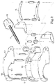
- the pipe cuter in accordance with the present invention comprises a body 10 having an arcuate plate 101 and the two side walls 102 extending from two opposite sides of the arcuate plate 101, each of the two side walls 102 having an arcuate slot 100 defined therethrough.
- a threaded rod 11 threadedly and movably extends through a tube 111 pivotally received in the first end of the body 10, and a first contacting member 12 is rotatably connected thereto the second end of the threaded rod 11.
- a knob 110 connected to one of two ends thereof and opposite to the first contacting member 12.
- a first link has a first end thereof pivotably connected to the body 10 and a second end thereof having a disk blade 14 rotatably connected thereto.
- the other end of the threaded rod 11 is pivotally connected to the first link 13 so that when moving the threaded rod 11, the disk blade 14 is moved toward the first contacting member 12.
- a second link 15 has a first end thereof pivotally connected to the first link 13 and a second end thereof having a second contacting member 16 rotatably connected thereto which has a pin extending through the second contacting member 16 so that two protrusions 160 extend centrally and longitudinally from two ends of the second contacting member 16 and respectively move within the two arcuate slots 100.
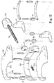
- the second contacting member 16 is moved according to the movement of the disk blade 14 so that when moving the disk blade 14 to an extreme position where the disk blade 14 contacts the first contacting member 12, the second contacting member 16 is located beside the first contacting member 12. Therefore, when clamping a small pipe 40, the three contacting points on the pipe 40 are located at an equal angular distance. Referring to Fig. 5, when a large pipe 41 is clamped by the pipe cuter, the first contacting member 12 and the second contacting member 16 are separated wide apart so as to firmly hold the pipe 41.
- Each of the two side walls 102 has an arcuate recess 103 defined in one of two sides thereof so as to receive a pipe 40 to be cut. It is to be noted that each of the first link 13 and the second link 15 includes two plates connected with each other with a gap defined between the two plates so that the total weight of the pipe cutter is reduced.
- the two plates and the two side walls 102 can be made of plastic material, and are connected together by rivets so as to conveniently assemble the pipe cutter.
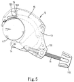
- the pipe cutter comprises a body 20 having an arcuate plate 201 and two side walls 202 extend from two opposite sides of the arcuate plate 201.
- the body 20 has the first end thereof with a threaded rod 21 movably and pivotally extending therethrough and a second end having a first contacting member 22 rotatably connected thereto.
- the threaded rod 21 extends through the tube 211 which is pivotally received in the first end of the body 20.
- a guide roller 200 is connected between the two side walls 202, and a knob 210 is connected to the threaded rod 21.
- Each of the two side walls 202 has an arcuate recess 203 defined in one of two sides thereof so as to be adapted to receive a pipe to be cut.
- a first link 23 has a first end thereof pivotably connected to the body 20 and a second end thereof having a disk blade 24 rotatably connected thereto, the threaded rod 21 pivotally connected to the first link 23.
- a second link 25 has a first end thereof pivotally connected to the first link 23 and a second end thereof having a second contacting member 26 rotatably connected thereto.
- a spring 250 is biased between the second link 25 and the body 20 and the guide roller 200 rolls on the back of the second link 25 when the second link 25 moves.
- the second link 25 has a raised portion 251 which contacts the guide roller 200 when the second contacting member 26 is moved beside the first contacting member 22 as shown in Fig. 8.
- Each of the first link 23 and the second link 25 includes two plates connected with each other with a gap defined between the two plates.
- Figures 8 and 9 respectively show the pipe cutter clamps a small pipe 42 and a large pipe 43, wherein the second link 25 moves by rolling on the guide roller 200 and the spring 250 pulls the second link 25 to contact the guide roller 200.
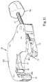
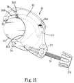
- Figures 11 to 13 show the third embodiment of the pipe cutter of the present invention which comprises a body 30 having an arcuate plate 301 and two side walls 302 extend from two opposite sides of the arcuate plate 301.
- Each of the two side walls 302 has an arcuate recess 303 and an arcuate notch 300 respectively defined in one of two sides thereof, the arcuate recess 303 communicating with the arcuate notch 300.
- the body 30 has a first end with a threaded rod 31 pivotally extending therethrough and a second end thereof having a first contacting member 32 rotatably connected thereto.
- the threaded rod 31 extends through a tube 311 pivotally received in the first end of the body 30 and a knob 310 is connected to one of two ends of the threaded rod 31.
- a first link 33 has a first end thereof pivotably connected to the body 30 and a second end thereof having a disk blade 34 rotatably connected thereto, the rod 31 pivotally connected to the first link 33.
- a second link 35 has a first end thereof pivotally connected to the first link 33 and a second end thereof having a second contacting member 36 rotatably connected thereto.
- a pin extends through the second contacting member 36 so as to have two protrusions 360 extending centrally and longitudinally from two ends of the second contacting member 36 such that the two protrusions 360 move along the two arcuate notches 300.
- Each of the first link 33 and the second link 35 includes two plates connected with each other with a gap defined between the two plates.
- Figs. 14 and 15 which respectively show a small pipe 44 and a large pipe 45 clamped by the pipe cutter, the second contacting member 36 is moved according to the sizes of the pipes 44, 45.
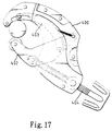
- FIGs. 16 to 18 showing the fourth embodiment of the pipe cutter of the present invention, wherein the structure of the pipe cutter is the same as that shown in Figs. 11 to 15 except that the fourth embodiment has no the arcuate plate 301 as shown in Fig. 12.
- the two side walls 400 of the fourth embodiment of the pipe cutter are connected together by several rivets 401 so that all the parts such as the two links 402, 403 and the threaded rod 404 are received between the two side walls 400.
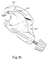
- Figures 19 and 20 show the fifth embodiment of the pipe cutter of the present invention, wherein the pipe cuter of the fifth embodiment is the same as that of the fourth embodiment except that a connecting plate 501 connects the two side walls 500 of the fifth embodiment and the connecting plate 501 is made of flexible and durable material so that the two side walls 500 can be folded toward to each other corresponding to the connecting plate 501, and the two side walls 500 are further connected by rivets 502.
Landscapes
- Engineering & Computer Science (AREA)
- Mechanical Engineering (AREA)
- Scissors And Nippers (AREA)
Applications Claiming Priority (2)
| Application Number | Priority Date | Filing Date | Title |
|---|---|---|---|
| US167145 | 1988-03-25 | ||
| US09/167,145 US6055732A (en) | 1998-10-06 | 1998-10-06 | Pipe cutter |
Publications (2)
| Publication Number | Publication Date |
|---|---|
| EP0992311A1 true EP0992311A1 (de) | 2000-04-12 |
| EP0992311B1 EP0992311B1 (de) | 2003-12-17 |
Family
ID=22606125
Family Applications (1)
| Application Number | Title | Priority Date | Filing Date |
|---|---|---|---|
| EP99119125A Expired - Lifetime EP0992311B1 (de) | 1998-10-06 | 1999-10-04 | Rohrschneider |
Country Status (3)
| Country | Link |
|---|---|
| US (2) | US6055732A (de) |
| EP (1) | EP0992311B1 (de) |
| DE (1) | DE69913633T2 (de) |
Cited By (1)
| Publication number | Priority date | Publication date | Assignee | Title |
|---|---|---|---|---|
| US20170173710A1 (en) * | 2015-12-16 | 2017-06-22 | Ridge Tool Company | C-type tubing cutter |
Families Citing this family (19)
| Publication number | Priority date | Publication date | Assignee | Title |
|---|---|---|---|---|
| US7568664B2 (en) * | 2005-07-01 | 2009-08-04 | Mark Mitchell | Hands free pipe holder |
| AU2006201052A1 (en) * | 2006-03-14 | 2007-10-04 | Stratford-Smith, Robert Michael Mr | Pipe Cut and Bevel Tool |
| GB2459829B (en) | 2007-03-15 | 2012-02-01 | Milwaukee Electric Tool Corp | Pipe cutter |
| CA2707183C (en) | 2007-11-28 | 2014-04-22 | Milwaukee Electric Tool Corporation | Pipe cutter |
| DE102008019437A1 (de) | 2008-04-17 | 2009-10-22 | Gottfried Wilhelm Leibniz Universität Hannover | Vorrichtung und spanloses Umformungsverfahren zum Einbringen eines Außenprofils in ein Werkstück |
| US9144447B2 (en) | 2009-10-14 | 2015-09-29 | K2M, Inc. | Surgical rod scorer and method of use of the same |
| US8714427B2 (en) * | 2009-10-14 | 2014-05-06 | K2M, Inc. | Surgical rod scorer and method of use of the same |
| US8506603B2 (en) | 2009-10-14 | 2013-08-13 | K2M, Inc. | Surgical rod scorer and method of use of the same |
| US9809484B2 (en) * | 2012-06-19 | 2017-11-07 | Patrick Lehoux | Bottle cutter |
| US9393709B2 (en) | 2012-06-26 | 2016-07-19 | K2M, Inc. | Mesh cage scoring and cutting system |
| ES2457094B1 (es) * | 2012-09-20 | 2015-01-27 | Zenten Bernhard Groten, S.L. | Herramienta cortatubos con dispositivo de ajuste |
| DE102012109340A1 (de) * | 2012-10-02 | 2014-04-03 | Ulrich Gmbh & Co. Kg | Werkzeug und Verfahren zum Kürzen eines Implantates mittels einer zu erzeugenden Sollbruchstelle |
| USD733267S1 (en) * | 2012-10-18 | 2015-06-30 | O'Brien Holding Co., Inc. | Pipe clamp |
| USD735003S1 (en) * | 2013-02-08 | 2015-07-28 | Steven Mattix | Pipe cutter |
| CN205218181U (zh) | 2015-06-15 | 2016-05-11 | 米沃奇电动工具公司 | 管道切割器 |
| USD813006S1 (en) | 2015-06-15 | 2018-03-20 | Milwaukee Electric Tool Corporation | Knob for a cutter |
| GB2583554A (en) * | 2019-04-30 | 2020-11-04 | Monument Tools Ltd | Pipe cutter |
| TWI768933B (zh) * | 2021-05-27 | 2022-06-21 | 詠基工業股份有限公司 | 適用多尺寸管徑的切管器 |
| USD1013474S1 (en) * | 2021-11-15 | 2024-02-06 | Scott Cutters Ltd | Pipe cutter |
Citations (3)
| Publication number | Priority date | Publication date | Assignee | Title |
|---|---|---|---|---|
| US2706853A (en) * | 1952-07-16 | 1955-04-26 | Frank R Wilson | Tube cutter |
| US3163932A (en) * | 1962-07-16 | 1965-01-05 | John H Adams | Adjustable size ratchet handle pipe cutter |
| FR2423296A1 (fr) * | 1978-04-04 | 1979-11-16 | Schillinger Maurice | Dispositif coupe-tubes |
Family Cites Families (9)
| Publication number | Priority date | Publication date | Assignee | Title |
|---|---|---|---|---|
| US565267A (en) * | 1896-08-04 | Pipe-cutter | ||
| US801866A (en) * | 1905-01-18 | 1905-10-17 | Headson Tool & Mfg Company | Pipe-cutting tool. |
| US812210A (en) * | 1905-07-20 | 1906-02-13 | Arpad M Barothy | Pipe-cutter. |
| FR405860A (fr) * | 1909-08-10 | 1910-01-15 | Joseph Frankstein | Cisailles |
| US1841251A (en) * | 1926-03-20 | 1932-01-12 | Kenneth W Miller | Cable tool |
| US2283572A (en) * | 1940-11-13 | 1942-05-19 | Reed Mfg Co | Pipe cutter |
| US2875518A (en) * | 1957-02-28 | 1959-03-03 | Erie Tool Works | Pipe cutting device |
| US2988814A (en) * | 1959-10-29 | 1961-06-20 | Weatherhead Co | Tube cutter |
| ES1025836Y (es) * | 1993-09-30 | 1994-08-16 | Super Ego Tools | Dispositivo de sujecion de tubos en cortatubos manuales. |
-
1998
- 1998-10-06 US US09/167,145 patent/US6055732A/en not_active Ceased
-
1999
- 1999-10-04 EP EP99119125A patent/EP0992311B1/de not_active Expired - Lifetime
- 1999-10-04 DE DE69913633T patent/DE69913633T2/de not_active Expired - Fee Related
-
2001
- 2001-01-18 US US09/771,243 patent/USRE40461E1/en not_active Expired - Lifetime
Patent Citations (3)
| Publication number | Priority date | Publication date | Assignee | Title |
|---|---|---|---|---|
| US2706853A (en) * | 1952-07-16 | 1955-04-26 | Frank R Wilson | Tube cutter |
| US3163932A (en) * | 1962-07-16 | 1965-01-05 | John H Adams | Adjustable size ratchet handle pipe cutter |
| FR2423296A1 (fr) * | 1978-04-04 | 1979-11-16 | Schillinger Maurice | Dispositif coupe-tubes |
Cited By (2)
| Publication number | Priority date | Publication date | Assignee | Title |
|---|---|---|---|---|
| US20170173710A1 (en) * | 2015-12-16 | 2017-06-22 | Ridge Tool Company | C-type tubing cutter |
| US10052701B2 (en) * | 2015-12-16 | 2018-08-21 | Ridge Tool Company | C-type tubing cutter |
Also Published As
| Publication number | Publication date |
|---|---|
| DE69913633T2 (de) | 2004-11-11 |
| US6055732A (en) | 2000-05-02 |
| USRE40461E1 (en) | 2008-08-26 |
| EP0992311B1 (de) | 2003-12-17 |
| DE69913633D1 (de) | 2004-01-29 |
Similar Documents
| Publication | Publication Date | Title |
|---|---|---|
| US6055732A (en) | Pipe cutter | |
| US5203083A (en) | Cutting device | |
| US5718051A (en) | Pipe cutter having an adjustable moving stroke | |
| US10569389B2 (en) | Pliers | |
| US4571808A (en) | Radiator hose separator pliers construction | |
| EP0756530B1 (de) | Handwerkzeug | |
| US20030019109A1 (en) | Cutting device with retractable blade | |
| EP0400576B1 (de) | Rohrbogen | |
| US5964130A (en) | Jaw members for a pair of pliers | |
| US6932074B2 (en) | Tile positioning device for a tile cutting machine | |
| EP0369957A2 (de) | Kabelabmantelungswerkzeug | |
| US6000268A (en) | Multifunction machine for modifying material in a bending brake | |
| US4633587A (en) | Spring-biased garden pruners | |
| US4152797A (en) | Precision small wire and untwisting tool | |
| US5899000A (en) | Hand held cutter | |
| GB2361658A (en) | Shears capable of cutting objects of different dimensions and profiles | |
| US5161445A (en) | Measuring stop assembly | |
| US6067693A (en) | Clamp with a pair of separable and adjustable arms | |
| US2979976A (en) | Plier-type tube bending tool | |
| US2618185A (en) | Material straightening tool | |
| US4087086A (en) | Tension clamp | |
| EP1687105A2 (de) | Blechabkantpresse mit verbessertem gelenk | |
| US3990806A (en) | Manual reamer for thin wall tubing | |
| GB2541448A (en) | A cutting apparatus | |
| JPH0657606U (ja) | 溝切りカッターにおける刃案内構造 |
Legal Events
| Date | Code | Title | Description |
|---|---|---|---|
| PUAI | Public reference made under article 153(3) epc to a published international application that has entered the european phase |
Free format text: ORIGINAL CODE: 0009012 |
|
| AK | Designated contracting states |
Kind code of ref document: A1 Designated state(s): DE ES FR GB IT NL |
|
| AX | Request for extension of the european patent |
Free format text: AL;LT;LV;MK;RO;SI |
|
| 17P | Request for examination filed |
Effective date: 20000905 |
|
| AKX | Designation fees paid |
Free format text: DE ES FR GB IT NL |
|
| 17Q | First examination report despatched |
Effective date: 20011130 |
|
| GRAH | Despatch of communication of intention to grant a patent |
Free format text: ORIGINAL CODE: EPIDOS IGRA |
|
| GRAS | Grant fee paid |
Free format text: ORIGINAL CODE: EPIDOSNIGR3 |
|
| GRAA | (expected) grant |
Free format text: ORIGINAL CODE: 0009210 |
|
| AK | Designated contracting states |
Kind code of ref document: B1 Designated state(s): DE ES FR GB IT NL |
|
| PG25 | Lapsed in a contracting state [announced via postgrant information from national office to epo] |
Ref country code: NL Free format text: LAPSE BECAUSE OF FAILURE TO SUBMIT A TRANSLATION OF THE DESCRIPTION OR TO PAY THE FEE WITHIN THE PRESCRIBED TIME-LIMIT Effective date: 20031217 Ref country code: IT Free format text: LAPSE BECAUSE OF FAILURE TO SUBMIT A TRANSLATION OF THE DESCRIPTION OR TO PAY THE FEE WITHIN THE PRESCRIBED TIME-LIMIT;WARNING: LAPSES OF ITALIAN PATENTS WITH EFFECTIVE DATE BEFORE 2007 MAY HAVE OCCURRED AT ANY TIME BEFORE 2007. THE CORRECT EFFECTIVE DATE MAY BE DIFFERENT FROM THE ONE RECORDED. Effective date: 20031217 Ref country code: FR Free format text: LAPSE BECAUSE OF FAILURE TO SUBMIT A TRANSLATION OF THE DESCRIPTION OR TO PAY THE FEE WITHIN THE PRESCRIBED TIME-LIMIT Effective date: 20031217 |
|
| REG | Reference to a national code |
Ref country code: GB Ref legal event code: FG4D |
|
| REF | Corresponds to: |
Ref document number: 69913633 Country of ref document: DE Date of ref document: 20040129 Kind code of ref document: P |
|
| PG25 | Lapsed in a contracting state [announced via postgrant information from national office to epo] |
Ref country code: ES Free format text: LAPSE BECAUSE OF FAILURE TO SUBMIT A TRANSLATION OF THE DESCRIPTION OR TO PAY THE FEE WITHIN THE PRESCRIBED TIME-LIMIT Effective date: 20040328 |
|
| NLV1 | Nl: lapsed or annulled due to failure to fulfill the requirements of art. 29p and 29m of the patents act | ||
| PG25 | Lapsed in a contracting state [announced via postgrant information from national office to epo] |
Ref country code: GB Free format text: LAPSE BECAUSE OF NON-PAYMENT OF DUE FEES Effective date: 20041004 |
|
| PLBE | No opposition filed within time limit |
Free format text: ORIGINAL CODE: 0009261 |
|
| STAA | Information on the status of an ep patent application or granted ep patent |
Free format text: STATUS: NO OPPOSITION FILED WITHIN TIME LIMIT |
|
| 26N | No opposition filed |
Effective date: 20040920 |
|
| EN | Fr: translation not filed | ||
| GBPC | Gb: european patent ceased through non-payment of renewal fee |
Effective date: 20041004 |
|
| PGFP | Annual fee paid to national office [announced via postgrant information from national office to epo] |
Ref country code: DE Payment date: 20081010 Year of fee payment: 10 |
|
| PG25 | Lapsed in a contracting state [announced via postgrant information from national office to epo] |
Ref country code: DE Free format text: LAPSE BECAUSE OF NON-PAYMENT OF DUE FEES Effective date: 20100501 |