EP0990891A1 - Method and apparatus for inspection of rubber product - Google Patents
Method and apparatus for inspection of rubber product Download PDFInfo
- Publication number
- EP0990891A1 EP0990891A1 EP99111427A EP99111427A EP0990891A1 EP 0990891 A1 EP0990891 A1 EP 0990891A1 EP 99111427 A EP99111427 A EP 99111427A EP 99111427 A EP99111427 A EP 99111427A EP 0990891 A1 EP0990891 A1 EP 0990891A1
- Authority
- EP
- European Patent Office
- Prior art keywords
- rubber product
- light
- rubber
- image pickup
- picked
- Prior art date
- Legal status (The legal status is an assumption and is not a legal conclusion. Google has not performed a legal analysis and makes no representation as to the accuracy of the status listed.)
- Granted
Links
- 238000007689 inspection Methods 0.000 title claims abstract description 23
- 238000000034 method Methods 0.000 title claims abstract description 20
- 230000007547 defect Effects 0.000 claims abstract description 25
- 238000005286 illumination Methods 0.000 claims abstract description 10
- 230000001678 irradiating effect Effects 0.000 claims abstract description 7
- 230000005540 biological transmission Effects 0.000 claims description 16
- 239000000463 material Substances 0.000 claims description 8
- 239000004636 vulcanized rubber Substances 0.000 claims description 8
- 239000000758 substrate Substances 0.000 description 16
- 230000002950 deficient Effects 0.000 description 4
- 239000003086 colorant Substances 0.000 description 2
- 238000005516 engineering process Methods 0.000 description 2
- 230000010355 oscillation Effects 0.000 description 2
- 238000003909 pattern recognition Methods 0.000 description 2
- 239000012744 reinforcing agent Substances 0.000 description 2
- 238000010276 construction Methods 0.000 description 1
- 238000011109 contamination Methods 0.000 description 1
- 238000001514 detection method Methods 0.000 description 1
- 238000012986 modification Methods 0.000 description 1
- 230000004048 modification Effects 0.000 description 1
- 238000002834 transmittance Methods 0.000 description 1
- 238000011179 visual inspection Methods 0.000 description 1
- 238000004073 vulcanization Methods 0.000 description 1
Images
Classifications
-
- G—PHYSICS
- G01—MEASURING; TESTING
- G01N—INVESTIGATING OR ANALYSING MATERIALS BY DETERMINING THEIR CHEMICAL OR PHYSICAL PROPERTIES
- G01N21/00—Investigating or analysing materials by the use of optical means, i.e. using sub-millimetre waves, infrared, visible or ultraviolet light
- G01N21/84—Systems specially adapted for particular applications
- G01N21/88—Investigating the presence of flaws or contamination
- G01N21/8806—Specially adapted optical and illumination features
Definitions
- the present invention relates to a method and apparatus for inspecting defects of a rubber product, such as a rubber plug for use in medical supplies or medical implements, or for inspecting defects in a rubber sheet.
- the primary object of the present invention is to provide an inspection method and apparatus in which internal flaws of a rubber product can be examined.
- Another object of the present invention is to provide an inspection method and apparatus in which surface flaws and internal flaw of a rubber product can be examined simultaneously.
- a rubber product inspection method for inspecting internal flaws of a vulcanized rubber product, the rubber product having light-transmitting properties, wherein the method includes: irradiating illumination light onto the rubber product, so that the light transmitted through the rubber product can be picked-up by an image pickup device; and detecting internal flaws in the rubber product, based on an image of the transmitted light picked-up by the image pickup device.
- a rubber product inspection method for inspecting internal flaws and surface defects of a vulcanized rubber product, the rubber product having light-transmitting properties, wherein the method includes: irradiating illumination light onto the rubber product, so that the light transmitted through the rubber product can be picked-up by an image pickup device; irradiating illumination light onto the rubber product, so that the light reflected by the rubber product can be picked-up by the image pickup device; detecting internal flaws in the rubber product, based on an image of the transmitted light picked-up by the image pickup device; and detecting surface defects on the rubber product, based on an image of the reflected light picked-up by the image pickup device.
- a rubber product inspection apparatus including: a table on which a vulcanized rubber product is placed, the rubber product and the table having light-transmitting properties; light sources above and below the table, for producing reflected light and transmission light; and an image pickup CCD camera which is provided on the same side of the table as the light source for the reflected light; the image pickup CCD camera receiving the light emitted from the light source for the transmission light which is transmitted through the rubber product, and receiving the light emitted from the light source for the reflected light which is reflected by the rubber product.
- the light source for producing transmission light and the light source for producing reflected light are turned ON at different times.
- a rubber product inspection apparatus including: a table on which a rubber product of vulcanized rubber material is placed, the table and the rubber material having light-transmitting properties; a light source which is provided on one side of the table, for producing transmission light; and an image pickup CCD camera which is provided on the other side of the table and which receives the light emitted from the light source for the light transmitted through the rubber product.
- the rubber product can be a rubber plug for use in medical supplies or medical implements.
- the rubber product can be a rubber sheet.
- a rubber product made of a transparent or translucent rubber material is in the form of a rubber plug 12 for use in medical supplies or medical implements.
- a number of rubber plugs 12 are integrally vulcanized on a substrate 11.
- Various kinds of transparent or translucent rubber materials are known, and a type appropriate for use in medical supplies or medical implements is selected.
- the rubber material of which the substrate 11 and the rubber plugs 12 are made may be mixed with an inorganic reinforcing agent or coloring agent, but it is preferable that such a reinforcing agent or coloring agent not be used in order to possess maximum transparency.
- a plurality of rubber plugs 12 are positioned upward on the substrate 11, the substrate 11 being placed on a transparent or translucent table 13.
- the table 13 is not limited to a specific shape so long as illumination light can be uniformly irradiated onto the rubber plugs 12. Moreover, the table 13 can be either movable or immovable.
- a light source 20 for reflected light and a light source 21 for transmission light are each made of an annular lighting element having a center opening.
- a CCD camera 30 is provided in the center opening of the light source 20 for reflected light.
- the CCD camera 30 is arranged so as to receive the light emitted from the light source 20 and reflected by the substrate 11 and the rubber plugs 12, and the light emitted from the light source 21 and transmitted through the substrate 11 and the rubber plugs 12.
- the CCD camera 30 is connected to an image examination circuit 31 which is in turn connected to a defect indication device 32.
- the CCD camera 30 for recognizing an image pattern is known in the art.
- the light sources 20 and 21 are turned ON at different times to emit light by a first and a second step, so that the image is picked up by the CCD camera 30 and is examined by the image examination circuit 31 to examine surface defects and internal flaws of the rubber plugs 12.
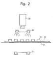
- the first step the light source 20 to produce reflected light is activated to illuminate the substrate 11 and the rubber plugs 12, and the light reflected by the substrate 11 and the rubber plugs 12 is picked-up by the CCD camera 30, as shown in Fig. 2.
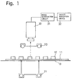
- the second step is carried out at a different timing from the first step, in which the light source 21 to produce transmission light is activated to illuminate the substrate 11 and the rubber plugs 12 with the illumination light, and the light transmitted through the substrate 11 and the rubber plugs 12 is picked-up by the CCD camera 30, as shown in Fig. 1.
- the order of the first and second step can be changed.
- the image examination circuit 31 has pre-stored therein flawless images formed by the reflected light and by the transmission light using a flawless substrate 11 and rubber plugs 12 which have no surface defects or no internal flaws.
- the presence or absence of the defects can be determined via pattern recognition technology.
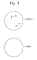
- the image examination circuit 31 compares the stored flawless image 40 formed by the reflected light with the actual image 40X of the rubber plugs 12 under examination formed by the reflected light.
- the image examination circuit 31 compares the stored flawless image 41 formed by the transmission light with the actual image 41X of the rubber plugs 12 under examination formed by the transmission light. If the reflection light image 40X or the transmission light image 41X contains a defect XX or YY as shown in Fig. 3, it is determined that the rubber plugs 12 contain a surface defect or an internal flaw, which is indicated by the defect indication device 32.
- the pattern recognition technology as described herein is known in the art.
- the rubber plugs 12 are moved to a subsequent stage in which the rubber plugs 12 are cut and separated from the substrate 11 to obtain rubber products.
- the rubber plugs 12 which are determined as defective are rejected.
- the rubber plug 12 contains a surface defect or an internal flaw, the plug is usually rejected. Therefore, in general, it is not necessary to distinguishably indicate the surface defect and the internal flaw. However, for example, if the surface defect can be removed or repaired, it would be useful to distinguishably indicate a surface defect from an internal flaw. Separate indication is also useful to determine a defective portion of a vulcanization line.
- the image pickup operation of the rubber plugs 12 by the CCD camera 30 can be carried out while moving the table 13; a plurality of images of the rubber plugs 12 can be picked-up by one image pickup operation; an indicia or mark, etc., can be printed on a defective plug 12 by a printer; the defective plug 12 can be cut and removed from the substrate 11 at the subsequent stage and thereafter, the good products are cut in a subsequent step.
- the oscillation wavelength of the reflection light source 20 can be different from the oscillation wavelength of the transmission light source 21, depending on the transmittance or reflectance of the substrate 11 and the rubber plugs 12.
- rear surface defects of the substrate 11 are not inspected. If the surface defect on the rear surface (rear surface in Fig. 1 and 2) of the substrate 11 should be also examined, the surface is irradiated with the illumination light emitted from the reflection light source, so that the light reflected thereby can be received by the CCD camera to carry out the same image examination as above.
Landscapes
- Physics & Mathematics (AREA)
- Health & Medical Sciences (AREA)
- Life Sciences & Earth Sciences (AREA)
- Chemical & Material Sciences (AREA)
- Analytical Chemistry (AREA)
- Biochemistry (AREA)
- General Health & Medical Sciences (AREA)
- General Physics & Mathematics (AREA)
- Immunology (AREA)
- Pathology (AREA)
- Investigating Materials By The Use Of Optical Means Adapted For Particular Applications (AREA)
Abstract
Description
- The present invention relates to a method and apparatus for inspecting defects of a rubber product, such as a rubber plug for use in medical supplies or medical implements, or for inspecting defects in a rubber sheet.
- For plugs used in medical supplies or medical implements, not only must surface flaws, such as surface marks or stains, etc., be examined in accordance with sanitary and safety requirements to prevent contamination by foreign matter, but also internal flaws, such as embedded foreign matter. If we ignore the inefficiency drawback, surface flaws can be detected by visual inspection; however, internal flaws cannot be detection by such a method.
- The primary object of the present invention is to provide an inspection method and apparatus in which internal flaws of a rubber product can be examined.
- Another object of the present invention is to provide an inspection method and apparatus in which surface flaws and internal flaw of a rubber product can be examined simultaneously.
- In order to achieve the above mentioned objects, there is provided a rubber product inspection method for inspecting internal flaws of a vulcanized rubber product, the rubber product having light-transmitting properties, wherein the method includes: irradiating illumination light onto the rubber product, so that the light transmitted through the rubber product can be picked-up by an image pickup device; and detecting internal flaws in the rubber product, based on an image of the transmitted light picked-up by the image pickup device.
- Alternatively, there is provided a rubber product inspection method for inspecting internal flaws and surface defects of a vulcanized rubber product, the rubber product having light-transmitting properties, wherein the method includes: irradiating illumination light onto the rubber product, so that the light transmitted through the rubber product can be picked-up by an image pickup device; irradiating illumination light onto the rubber product, so that the light reflected by the rubber product can be picked-up by the image pickup device; detecting internal flaws in the rubber product, based on an image of the transmitted light picked-up by the image pickup device; and detecting surface defects on the rubber product, based on an image of the reflected light picked-up by the image pickup device.
- Alternatively, there is provided a rubber product inspection apparatus including: a table on which a vulcanized rubber product is placed, the rubber product and the table having light-transmitting properties; light sources above and below the table, for producing reflected light and transmission light; and an image pickup CCD camera which is provided on the same side of the table as the light source for the reflected light; the image pickup CCD camera receiving the light emitted from the light source for the transmission light which is transmitted through the rubber product, and receiving the light emitted from the light source for the reflected light which is reflected by the rubber product.
- Preferably, the light source for producing transmission light and the light source for producing reflected light are turned ON at different times.
- Alternatively, there is provided a rubber product inspection apparatus including: a table on which a rubber product of vulcanized rubber material is placed, the table and the rubber material having light-transmitting properties; a light source which is provided on one side of the table, for producing transmission light; and an image pickup CCD camera which is provided on the other side of the table and which receives the light emitted from the light source for the light transmitted through the rubber product.
- The rubber product can be a rubber plug for use in medical supplies or medical implements. Alternatively, the rubber product can be a rubber sheet.
- The invention will be discussed below in detail with reference to the accompanying drawings, in which:
- Figure 1 is a conceptual view of an inspection method and apparatus for a rubber product, according to the present invention;
- Figure 2 is a conceptual view of another inspection process in an inspection apparatus shown in Fig. 1; and
- Figure 3 is a schematic view of samples of an image formed by transmission light (or reflected light) and a correct image, by way of example.
-
- In the illustrated embodiment, a rubber product made of a transparent or translucent rubber material (a rubber material having light-transmitting properties) is in the form of a
rubber plug 12 for use in medical supplies or medical implements. A number ofrubber plugs 12 are integrally vulcanized on asubstrate 11. Various kinds of transparent or translucent rubber materials are known, and a type appropriate for use in medical supplies or medical implements is selected. The rubber material of which thesubstrate 11 and therubber plugs 12 are made may be mixed with an inorganic reinforcing agent or coloring agent, but it is preferable that such a reinforcing agent or coloring agent not be used in order to possess maximum transparency. - A plurality of
rubber plugs 12 are positioned upward on thesubstrate 11, thesubstrate 11 being placed on a transparent or translucent table 13. The table 13 is not limited to a specific shape so long as illumination light can be uniformly irradiated onto therubber plugs 12. Moreover, the table 13 can be either movable or immovable. - Above and below the table 13 are provided a
light source 20 for reflected light and alight source 21 for transmission light, respectively. Thelight sources CCD camera 30 is provided in the center opening of thelight source 20 for reflected light. TheCCD camera 30 is arranged so as to receive the light emitted from thelight source 20 and reflected by thesubstrate 11 and therubber plugs 12, and the light emitted from thelight source 21 and transmitted through thesubstrate 11 and therubber plugs 12. TheCCD camera 30 is connected to animage examination circuit 31 which is in turn connected to adefect indication device 32. TheCCD camera 30 for recognizing an image pattern is known in the art. - In the apparatus construction described above, the
light sources CCD camera 30 and is examined by theimage examination circuit 31 to examine surface defects and internal flaws of therubber plugs 12. Namely, in the first step, thelight source 20 to produce reflected light is activated to illuminate thesubstrate 11 and therubber plugs 12, and the light reflected by thesubstrate 11 and therubber plugs 12 is picked-up by theCCD camera 30, as shown in Fig. 2. The second step is carried out at a different timing from the first step, in which thelight source 21 to produce transmission light is activated to illuminate thesubstrate 11 and therubber plugs 12 with the illumination light, and the light transmitted through thesubstrate 11 and therubber plugs 12 is picked-up by theCCD camera 30, as shown in Fig. 1. The order of the first and second step can be changed. - The
image examination circuit 31 has pre-stored therein flawless images formed by the reflected light and by the transmission light using aflawless substrate 11 andrubber plugs 12 which have no surface defects or no internal flaws. The presence or absence of the defects can be determined via pattern recognition technology. For example, as schematically shown in Fig. 3, theimage examination circuit 31 compares the storedflawless image 40 formed by the reflected light with theactual image 40X of therubber plugs 12 under examination formed by the reflected light. Similarly, theimage examination circuit 31 compares the storedflawless image 41 formed by the transmission light with theactual image 41X of therubber plugs 12 under examination formed by the transmission light. If thereflection light image 40X or thetransmission light image 41X contains a defect XX or YY as shown in Fig. 3, it is determined that therubber plugs 12 contain a surface defect or an internal flaw, which is indicated by thedefect indication device 32. The pattern recognition technology as described herein is known in the art. - If the examination shows that there is no surface defect or internal flaw, the
rubber plugs 12 are moved to a subsequent stage in which therubber plugs 12 are cut and separated from thesubstrate 11 to obtain rubber products. Therubber plugs 12 which are determined as defective are rejected. - It is possible to indicate the surface defects and the internal flaws separately or without distinguishing them. If the
rubber plug 12 contains a surface defect or an internal flaw, the plug is usually rejected. Therefore, in general, it is not necessary to distinguishably indicate the surface defect and the internal flaw. However, for example, if the surface defect can be removed or repaired, it would be useful to distinguishably indicate a surface defect from an internal flaw. Separate indication is also useful to determine a defective portion of a vulcanization line. - The above discussion has been addressed to the simplest inspection method and apparatus according to the present invention. The illustrated embodiment can be modified. For example: the image pickup operation of the
rubber plugs 12 by theCCD camera 30 can be carried out while moving the table 13; a plurality of images of therubber plugs 12 can be picked-up by one image pickup operation; an indicia or mark, etc., can be printed on adefective plug 12 by a printer; thedefective plug 12 can be cut and removed from thesubstrate 11 at the subsequent stage and thereafter, the good products are cut in a subsequent step. - Furthermore, the oscillation wavelength of the
reflection light source 20 can be different from the oscillation wavelength of thetransmission light source 21, depending on the transmittance or reflectance of thesubstrate 11 and therubber plugs 12. - In the embodiment mentioned above, rear surface defects of the
substrate 11 are not inspected. If the surface defect on the rear surface (rear surface in Fig. 1 and 2) of thesubstrate 11 should be also examined, the surface is irradiated with the illumination light emitted from the reflection light source, so that the light reflected thereby can be received by the CCD camera to carry out the same image examination as above. - As can be understood from the above discussion, internal defects of a rubber product can be examined. Moreover, since the surface defects can be also examined in addition to the internal defects, a full examination can be carried out. Furthermore, the inspection method can be executed by a simple inspection apparatus.
- Obvious changes may be made in the specific embodiment of the present invention described herein, such modifications being within the spirit and scope of the invention claimed. It is indicated that all matter contained herein is illustrative and does not limit the scope of the present invention.
Claims (7)
- A rubber product inspection method for inspecting internal flaws of a vulcanized rubber product, said rubber product having light-transmitting properties, wherein said method comprises:irradiating illumination light onto said rubber product, so that the light transmitted through said rubber product can be picked-up by an image pickup device; anddetecting internal flaws in the rubber product, based on an image of the transmitted light picked-up by said image pickup device.
- A rubber product inspection method for inspecting internal flaws and surface defects of a vulcanized rubber product, said rubber product having light-transmitting properties, wherein said method comprises:irradiating illumination light onto said rubber product, so that the light transmitted through said rubber product can be picked-up by an image pickup device;irradiating illumination light onto said rubber product, so that the light reflected by said rubber product can be picked-up by said image pickup device;detecting internal flaws in the rubber product, based on an image of the transmitted light picked-up by said image pickup device; anddetecting surface defects on the rubber product, based on an image of the reflected light picked-up by said image pickup device.
- A rubber product inspection apparatus comprising:a table on which a vulcanized rubber product is placed, said rubber product and said table having light-transmitting properties;light sources above and below said table, for producing reflected light and transmission light; andan image pickup CCD camera which is provided on the same side of said table as the light source for the reflected light; said image pickup CCD camera receiving the light emitted from the light source for the transmission light which is transmitted through the rubber product, and receiving the light emitted from the light source for the reflected light which is reflected by the rubber product.
- A rubber product inspection apparatus according to claim 3, wherein the light source for producing transmission light and the light source for producing reflected light are turned ON at different times.
- A rubber product inspection apparatus comprising:a table on which a rubber product of vulcanized rubber material is placed, said table and said rubber material having light transmitting properties;a light source which is provided on one side of said table, for producing transmission light; andan image pickup CCD camera which is provided on the other side of said table and which receives the light emitted from the light source for the light transmitted through the rubber product.
- A rubber product inspection apparatus according to anyone of the foregoing claims, wherein the rubber product is a rubber plug for use in medical supplies or medical implements.
- A rubber product inspection method according to anyone of claims 1 to 5, wherein said rubber product is a rubber sheet.
Applications Claiming Priority (2)
| Application Number | Priority Date | Filing Date | Title |
|---|---|---|---|
| JP27864898A JP3330089B2 (en) | 1998-09-30 | 1998-09-30 | Inspection method and apparatus for rubber products |
| JP27864898 | 1998-09-30 |
Publications (2)
| Publication Number | Publication Date |
|---|---|
| EP0990891A1 true EP0990891A1 (en) | 2000-04-05 |
| EP0990891B1 EP0990891B1 (en) | 2012-07-11 |
Family
ID=17600216
Family Applications (1)
| Application Number | Title | Priority Date | Filing Date |
|---|---|---|---|
| EP99111427A Expired - Lifetime EP0990891B1 (en) | 1998-09-30 | 1999-06-11 | Method for inspection of rubber product |
Country Status (5)
| Country | Link |
|---|---|
| US (1) | US6628379B1 (en) |
| EP (1) | EP0990891B1 (en) |
| JP (1) | JP3330089B2 (en) |
| CA (1) | CA2273833C (en) |
| DK (1) | DK0990891T3 (en) |
Cited By (5)
| Publication number | Priority date | Publication date | Assignee | Title |
|---|---|---|---|---|
| WO2003034049A1 (en) * | 2001-10-16 | 2003-04-24 | Baader-Canpolar Inc. | Automatic inspection apparatus and method for detection of anomalies in a 3-dimensional translucent object |
| CN106442383A (en) * | 2016-09-13 | 2017-02-22 | 广西电网有限责任公司电力科学研究院 | Real time supervision method of aging level of anti-pollution-flashover RTV coating for power supply system |
| DE102021101152A1 (en) | 2021-01-20 | 2022-07-21 | Lippert Gmbh & Co. Kg | Process for the optical detection of defects in ceramic articles |
| EP4428529A1 (en) * | 2023-03-06 | 2024-09-11 | Tellus Products, LLC | Apparatus and method for automated inspection of molded pulp and other batch-produced products |
| EP4229386A4 (en) * | 2020-10-15 | 2024-10-02 | Applied Materials, Inc. | TRANSPARENCY METROLOGY SYSTEMS, APPARATUSES AND METHODS FOR OPTICAL DEVICES |
Families Citing this family (13)
| Publication number | Priority date | Publication date | Assignee | Title |
|---|---|---|---|---|
| DE10126185B4 (en) * | 2001-05-30 | 2007-07-19 | Robert Bosch Gmbh | Test specimen for optoelectronic image analysis systems |
| JP2004219122A (en) * | 2003-01-10 | 2004-08-05 | Dainippon Printing Co Ltd | Inspection apparatus and inspection method for foreign matter defect |
| US7142295B2 (en) * | 2003-03-05 | 2006-11-28 | Corning Incorporated | Inspection of transparent substrates for defects |
| US7339664B2 (en) * | 2004-09-29 | 2008-03-04 | General Electric Company | System and method for inspecting a light-management film and method of making the light-management film |
| JP5134806B2 (en) * | 2006-10-12 | 2013-01-30 | 株式会社朝日ラバー | Rubber molded body slit inspection device and rubber molded body slit inspection method |
| US7551274B1 (en) * | 2007-02-28 | 2009-06-23 | Lite Sentry Corporation | Defect detection lighting system and methods for large glass sheets |
| US20100195096A1 (en) * | 2009-02-04 | 2010-08-05 | Applied Materials, Inc. | High efficiency multi wavelength line light source |
| JP4796160B2 (en) * | 2009-02-27 | 2011-10-19 | 三菱重工業株式会社 | Thin film inspection apparatus and inspection method |
| CN101532958B (en) * | 2009-04-28 | 2010-08-18 | 南京航空航天大学 | Method and system for measuring dry rubber content in concentrated latex based on photoelectric sensor |
| TWI484164B (en) * | 2012-05-11 | 2015-05-11 | Machvision Inc | Optical re - inspection system and its detection method |
| US10126247B2 (en) | 2015-07-30 | 2018-11-13 | Zeon Chemicals L.P. | Rubber crumb inspection system |
| JP6895768B2 (en) * | 2017-03-01 | 2021-06-30 | Hoya株式会社 | Defect inspection equipment and defect inspection method |
| JP7370265B2 (en) * | 2020-01-30 | 2023-10-27 | 株式会社ディスコ | Processing method and processing equipment |
Citations (5)
| Publication number | Priority date | Publication date | Assignee | Title |
|---|---|---|---|---|
| DE3611574A1 (en) * | 1986-04-07 | 1987-10-08 | Georg Markthaler | Quality control device |
| DD279828A1 (en) * | 1989-02-07 | 1990-06-20 | Ottendorf Okrilla Presswerk | METHOD AND DEVICE FOR DETECTING ERRORS ON PHARMACEUTICAL STOCKS |
| JPH0743314A (en) * | 1993-08-02 | 1995-02-14 | Sumitomo Wiring Syst Ltd | Inspection device for rubber plug |
| US5598262A (en) * | 1992-10-20 | 1997-01-28 | Thomson-Csf | Process and device for inspecting transparent material |
| DE29707985U1 (en) * | 1997-05-03 | 1997-07-24 | Piller GmbH, 53894 Mechernich | Device for the optical examination of workpieces |
Family Cites Families (18)
| Publication number | Priority date | Publication date | Assignee | Title |
|---|---|---|---|---|
| DE279828C (en) | ||||
| US3715476A (en) * | 1969-01-16 | 1973-02-06 | Nippon Steel Corp | Method and apparatus for detecting pinholes on sheet articles |
| JPS576307A (en) * | 1980-06-13 | 1982-01-13 | Toyota Central Res & Dev Lab Inc | Method and apparatus of surface failure inspection of circular member |
| US4389575A (en) * | 1980-07-03 | 1983-06-21 | Sparton Corporation | Fabric inspection system |
| JPS58190707A (en) * | 1982-04-30 | 1983-11-07 | Toyoda Gosei Co Ltd | Surface inspecting method |
| JPS6383641A (en) * | 1986-09-29 | 1988-04-14 | Hiyuutec:Kk | Defect inspection method |
| JP3031926B2 (en) * | 1989-09-28 | 2000-04-10 | 株式会社ロゼフテクノロジー | Inspection method for workpieces such as rubber products |
| JP3072998B2 (en) * | 1990-04-18 | 2000-08-07 | 株式会社日立製作所 | Soldering condition inspection method and apparatus |
| US5197105A (en) * | 1990-05-30 | 1993-03-23 | Dainippon Screen Mfg. Co. Ltd. | Method of reading optical image of inspected surface and image reading system employabale therein |
| US5329133A (en) * | 1991-03-06 | 1994-07-12 | The Furukawa Electric Co., Ltd. | Method of automatically determining flaws of an object of examination |
| JP2795595B2 (en) * | 1992-06-26 | 1998-09-10 | セントラル硝子株式会社 | Defect detection method for transparent plate |
| JPH07159348A (en) * | 1993-12-10 | 1995-06-23 | Kirin Brewery Co Ltd | Pharmaceutical vial inspection device |
| US5666199A (en) * | 1994-07-11 | 1997-09-09 | Phillips Petroleum Company | Apparatus and process for detecting the presence of gel defects in oriented sheets or films based on polarization detection |
| JP3178644B2 (en) * | 1995-02-10 | 2001-06-25 | セントラル硝子株式会社 | Defect detection method for transparent plate |
| US6396579B1 (en) * | 1997-03-10 | 2002-05-28 | Shin-Etsu Chemical Co., Ltd. | Method, apparatus, and system for inspecting transparent objects |
| US5974167A (en) * | 1997-06-30 | 1999-10-26 | M.A.Hannarubbercompounding | System and method for measuring and controlling the quality of dispersion of filler particles in rubber compounds |
| US6011620A (en) * | 1998-04-06 | 2000-01-04 | Northrop Grumman Corporation | Method and apparatus for the automatic inspection of optically transmissive planar objects |
| JP2000346813A (en) * | 1999-06-07 | 2000-12-15 | Kanebo Ltd | Inspection device for surface of article |
-
1998
- 1998-09-30 JP JP27864898A patent/JP3330089B2/en not_active Expired - Lifetime
-
1999
- 1999-06-09 CA CA002273833A patent/CA2273833C/en not_active Expired - Lifetime
- 1999-06-10 US US09/329,390 patent/US6628379B1/en not_active Expired - Lifetime
- 1999-06-11 DK DK99111427.3T patent/DK0990891T3/en active
- 1999-06-11 EP EP99111427A patent/EP0990891B1/en not_active Expired - Lifetime
Patent Citations (5)
| Publication number | Priority date | Publication date | Assignee | Title |
|---|---|---|---|---|
| DE3611574A1 (en) * | 1986-04-07 | 1987-10-08 | Georg Markthaler | Quality control device |
| DD279828A1 (en) * | 1989-02-07 | 1990-06-20 | Ottendorf Okrilla Presswerk | METHOD AND DEVICE FOR DETECTING ERRORS ON PHARMACEUTICAL STOCKS |
| US5598262A (en) * | 1992-10-20 | 1997-01-28 | Thomson-Csf | Process and device for inspecting transparent material |
| JPH0743314A (en) * | 1993-08-02 | 1995-02-14 | Sumitomo Wiring Syst Ltd | Inspection device for rubber plug |
| DE29707985U1 (en) * | 1997-05-03 | 1997-07-24 | Piller GmbH, 53894 Mechernich | Device for the optical examination of workpieces |
Non-Patent Citations (1)
| Title |
|---|
| PATENT ABSTRACTS OF JAPAN vol. 1995, no. 05 30 June 1995 (1995-06-30) * |
Cited By (11)
| Publication number | Priority date | Publication date | Assignee | Title |
|---|---|---|---|---|
| WO2003034049A1 (en) * | 2001-10-16 | 2003-04-24 | Baader-Canpolar Inc. | Automatic inspection apparatus and method for detection of anomalies in a 3-dimensional translucent object |
| GB2400658A (en) * | 2001-10-16 | 2004-10-20 | Baader Canpolar Inc | Automatic inspection apparatus and method for detection of anomalies in a 3-dimensional translucent object |
| GB2400658B (en) * | 2001-10-16 | 2005-09-07 | Baader Canpolar Inc | Automatic inspection apparatus and method for detection of anomalies in a 3-dimensional translucent object |
| CN106442383A (en) * | 2016-09-13 | 2017-02-22 | 广西电网有限责任公司电力科学研究院 | Real time supervision method of aging level of anti-pollution-flashover RTV coating for power supply system |
| CN106442383B (en) * | 2016-09-13 | 2019-03-19 | 广西电网有限责任公司电力科学研究院 | A kind of degree of aging method of real-time of electric system antifouling work RTV coating |
| EP4229386A4 (en) * | 2020-10-15 | 2024-10-02 | Applied Materials, Inc. | TRANSPARENCY METROLOGY SYSTEMS, APPARATUSES AND METHODS FOR OPTICAL DEVICES |
| US12229940B2 (en) | 2020-10-15 | 2025-02-18 | Applied Materials, Inc. | In-line metrology systems, apparatus, and methods for optical devices |
| US12236575B2 (en) | 2020-10-15 | 2025-02-25 | Applied Materials, Inc. | In-line metrology systems, apparatus, and methods for optical devices |
| DE102021101152A1 (en) | 2021-01-20 | 2022-07-21 | Lippert Gmbh & Co. Kg | Process for the optical detection of defects in ceramic articles |
| EP4033226A1 (en) | 2021-01-20 | 2022-07-27 | Lippert GmbH & Co. KG | Method for optical detection of defects in ceramic articles |
| EP4428529A1 (en) * | 2023-03-06 | 2024-09-11 | Tellus Products, LLC | Apparatus and method for automated inspection of molded pulp and other batch-produced products |
Also Published As
| Publication number | Publication date |
|---|---|
| CA2273833A1 (en) | 2000-03-30 |
| JP2000111482A (en) | 2000-04-21 |
| JP3330089B2 (en) | 2002-09-30 |
| CA2273833C (en) | 2005-02-22 |
| DK0990891T3 (en) | 2012-10-22 |
| US6628379B1 (en) | 2003-09-30 |
| EP0990891B1 (en) | 2012-07-11 |
Similar Documents
| Publication | Publication Date | Title |
|---|---|---|
| US6628379B1 (en) | Method and apparatus for inspection of rubber product | |
| US6757420B2 (en) | Inspection device for packages | |
| JP3820348B2 (en) | Method for identifying scattered material, dirt and other defects in a transported object | |
| CA2578857C (en) | Ovd inspection method and inspection apparatus | |
| WO1997000423A1 (en) | Apparatus and method for inspecting coating film | |
| KR102340173B1 (en) | Contact lens inspection in a plastic shell | |
| US6061125A (en) | Dual illumination apparatus for container inspection | |
| KR20060053847A (en) | Defect inspection method of glass plate and device | |
| JPH0962831A (en) | Imaging device and lighting device | |
| JPH03231144A (en) | Package defect inspection device | |
| JP2004117103A (en) | Label tear inspection device of vessel | |
| JPH0792108A (en) | Inspection illuminator | |
| JP3244611B2 (en) | Liquid leakage detection method for liquid filled containers | |
| JPH0961374A (en) | Display body inspection method and display body inspection apparatus | |
| JPH04309850A (en) | Inspection of defective of glass cylindrical body | |
| JPH06160290A (en) | System and apparatus for inspecting foreign matter | |
| JP2000292369A (en) | Quality inspection device | |
| KR200336984Y1 (en) | A device for inspecting surface and shape of an object of examination | |
| WO2024053671A1 (en) | Resin molded article inspection method and inspection device | |
| JPH0738950U (en) | Inspection lighting device | |
| JP2002048729A (en) | Paper cup inspection equipment | |
| JPH0431755A (en) | Defect inspection equipment for sheet materials | |
| JPH046448A (en) | Laminated-plate inspecting method | |
| CN112683925A (en) | Image detection scanning method and system for possible defects on surface of object | |
| JPH08193915A (en) | Color sample inspection device |
Legal Events
| Date | Code | Title | Description |
|---|---|---|---|
| PUAI | Public reference made under article 153(3) epc to a published international application that has entered the european phase |
Free format text: ORIGINAL CODE: 0009012 |
|
| AK | Designated contracting states |
Kind code of ref document: A1 Designated state(s): AT BE CH DE DK FR GB IE IT LI NL SE |
|
| AX | Request for extension of the european patent |
Free format text: AL;LT;LV;MK;RO;SI |
|
| 17P | Request for examination filed |
Effective date: 20000417 |
|
| AKX | Designation fees paid |
Free format text: AT BE CH DE DK FR GB IE IT LI NL SE |
|
| RTI1 | Title (correction) |
Free format text: METHOD FOR INSPECTION OF RUBBER PRODUCT |
|
| GRAP | Despatch of communication of intention to grant a patent |
Free format text: ORIGINAL CODE: EPIDOSNIGR1 |
|
| GRAS | Grant fee paid |
Free format text: ORIGINAL CODE: EPIDOSNIGR3 |
|
| GRAA | (expected) grant |
Free format text: ORIGINAL CODE: 0009210 |
|
| AK | Designated contracting states |
Kind code of ref document: B1 Designated state(s): AT BE CH DE DK FR GB IE IT LI NL SE |
|
| REG | Reference to a national code |
Ref country code: GB Ref legal event code: FG4D |
|
| REG | Reference to a national code |
Ref country code: CH Ref legal event code: NV Representative=s name: SCHNEIDER FELDMANN AG PATENT- UND MARKENANWAELTE Ref country code: CH Ref legal event code: EP |
|
| REG | Reference to a national code |
Ref country code: AT Ref legal event code: REF Ref document number: 566380 Country of ref document: AT Kind code of ref document: T Effective date: 20120715 |
|
| REG | Reference to a national code |
Ref country code: IE Ref legal event code: FG4D |
|
| REG | Reference to a national code |
Ref country code: DE Ref legal event code: R096 Ref document number: 69944296 Country of ref document: DE Effective date: 20120830 |
|
| REG | Reference to a national code |
Ref country code: SE Ref legal event code: TRGR |
|
| REG | Reference to a national code |
Ref country code: DK Ref legal event code: T3 |
|
| REG | Reference to a national code |
Ref country code: NL Ref legal event code: VDEP Effective date: 20120711 |
|
| REG | Reference to a national code |
Ref country code: AT Ref legal event code: MK05 Ref document number: 566380 Country of ref document: AT Kind code of ref document: T Effective date: 20120711 |
|
| PG25 | Lapsed in a contracting state [announced via postgrant information from national office to epo] |
Ref country code: AT Free format text: LAPSE BECAUSE OF FAILURE TO SUBMIT A TRANSLATION OF THE DESCRIPTION OR TO PAY THE FEE WITHIN THE PRESCRIBED TIME-LIMIT Effective date: 20120711 |
|
| PG25 | Lapsed in a contracting state [announced via postgrant information from national office to epo] |
Ref country code: NL Free format text: LAPSE BECAUSE OF FAILURE TO SUBMIT A TRANSLATION OF THE DESCRIPTION OR TO PAY THE FEE WITHIN THE PRESCRIBED TIME-LIMIT Effective date: 20120711 |
|
| PLBE | No opposition filed within time limit |
Free format text: ORIGINAL CODE: 0009261 |
|
| STAA | Information on the status of an ep patent application or granted ep patent |
Free format text: STATUS: NO OPPOSITION FILED WITHIN TIME LIMIT |
|
| 26N | No opposition filed |
Effective date: 20130412 |
|
| REG | Reference to a national code |
Ref country code: DE Ref legal event code: R097 Ref document number: 69944296 Country of ref document: DE Effective date: 20130412 |
|
| REG | Reference to a national code |
Ref country code: DE Ref legal event code: R082 Ref document number: 69944296 Country of ref document: DE Representative=s name: SCHAUMBURG UND PARTNER PATENTANWAELTE MBB, DE Ref country code: DE Ref legal event code: R082 Ref document number: 69944296 Country of ref document: DE Representative=s name: SCHAUMBURG & PARTNER PATENTANWAELTE GBR, DE |
|
| REG | Reference to a national code |
Ref country code: FR Ref legal event code: PLFP Year of fee payment: 18 |
|
| REG | Reference to a national code |
Ref country code: FR Ref legal event code: PLFP Year of fee payment: 19 |
|
| REG | Reference to a national code |
Ref country code: FR Ref legal event code: PLFP Year of fee payment: 20 |
|
| PGFP | Annual fee paid to national office [announced via postgrant information from national office to epo] |
Ref country code: IE Payment date: 20180612 Year of fee payment: 20 Ref country code: DK Payment date: 20180612 Year of fee payment: 20 Ref country code: CH Payment date: 20180614 Year of fee payment: 20 Ref country code: DE Payment date: 20180530 Year of fee payment: 20 |
|
| PGFP | Annual fee paid to national office [announced via postgrant information from national office to epo] |
Ref country code: BE Payment date: 20180515 Year of fee payment: 20 Ref country code: FR Payment date: 20180511 Year of fee payment: 20 |
|
| PGFP | Annual fee paid to national office [announced via postgrant information from national office to epo] |
Ref country code: SE Payment date: 20180612 Year of fee payment: 20 |
|
| PGFP | Annual fee paid to national office [announced via postgrant information from national office to epo] |
Ref country code: GB Payment date: 20180606 Year of fee payment: 20 Ref country code: IT Payment date: 20180625 Year of fee payment: 20 |
|
| REG | Reference to a national code |
Ref country code: DE Ref legal event code: R071 Ref document number: 69944296 Country of ref document: DE |
|
| REG | Reference to a national code |
Ref country code: DK Ref legal event code: EUP Effective date: 20190611 |
|
| REG | Reference to a national code |
Ref country code: CH Ref legal event code: PL |
|
| REG | Reference to a national code |
Ref country code: GB Ref legal event code: PE20 Expiry date: 20190610 Ref country code: BE Ref legal event code: MK Effective date: 20190611 |
|
| REG | Reference to a national code |
Ref country code: SE Ref legal event code: EUG |
|
| REG | Reference to a national code |
Ref country code: IE Ref legal event code: MK9A |
|
| PG25 | Lapsed in a contracting state [announced via postgrant information from national office to epo] |
Ref country code: GB Free format text: LAPSE BECAUSE OF EXPIRATION OF PROTECTION Effective date: 20190610 Ref country code: IE Free format text: LAPSE BECAUSE OF EXPIRATION OF PROTECTION Effective date: 20190611 |