EP0989897B1 - Stabsiebkorb für fasersuspensionen und verfahren zu seiner herstellung - Google Patents
Stabsiebkorb für fasersuspensionen und verfahren zu seiner herstellung Download PDFInfo
- Publication number
- EP0989897B1 EP0989897B1 EP98934957A EP98934957A EP0989897B1 EP 0989897 B1 EP0989897 B1 EP 0989897B1 EP 98934957 A EP98934957 A EP 98934957A EP 98934957 A EP98934957 A EP 98934957A EP 0989897 B1 EP0989897 B1 EP 0989897B1
- Authority
- EP
- European Patent Office
- Prior art keywords
- screen
- profiled
- bars
- profiled bar
- profiled bars
- Prior art date
- Legal status (The legal status is an assumption and is not a legal conclusion. Google has not performed a legal analysis and makes no representation as to the accuracy of the status listed.)
- Expired - Lifetime
Links
- 239000000835 fiber Substances 0.000 title claims abstract description 46
- 239000000725 suspension Substances 0.000 title claims abstract description 43
- 238000004519 manufacturing process Methods 0.000 title claims description 17
- 238000000034 method Methods 0.000 title claims description 15
- 239000000463 material Substances 0.000 claims abstract description 31
- 238000006073 displacement reaction Methods 0.000 claims abstract description 15
- 230000001154 acute effect Effects 0.000 claims description 5
- 230000004323 axial length Effects 0.000 claims description 4
- 239000011324 bead Substances 0.000 claims description 2
- 230000002093 peripheral effect Effects 0.000 abstract description 6
- 239000002184 metal Substances 0.000 abstract description 2
- 238000013461 design Methods 0.000 description 6
- 238000005452 bending Methods 0.000 description 5
- 238000010438 heat treatment Methods 0.000 description 5
- 230000008569 process Effects 0.000 description 3
- 235000001674 Agaricus brunnescens Nutrition 0.000 description 2
- 230000035508 accumulation Effects 0.000 description 2
- 238000009825 accumulation Methods 0.000 description 2
- 230000002776 aggregation Effects 0.000 description 2
- 230000008901 benefit Effects 0.000 description 2
- 230000008859 change Effects 0.000 description 2
- 238000003825 pressing Methods 0.000 description 2
- 238000005096 rolling process Methods 0.000 description 2
- 238000003466 welding Methods 0.000 description 2
- TVEXGJYMHHTVKP-UHFFFAOYSA-N 6-oxabicyclo[3.2.1]oct-3-en-7-one Chemical compound C1C2C(=O)OC1C=CC2 TVEXGJYMHHTVKP-UHFFFAOYSA-N 0.000 description 1
- 238000005054 agglomeration Methods 0.000 description 1
- 238000004220 aggregation Methods 0.000 description 1
- 230000015572 biosynthetic process Effects 0.000 description 1
- 239000000969 carrier Substances 0.000 description 1
- 229910010293 ceramic material Inorganic materials 0.000 description 1
- 238000004140 cleaning Methods 0.000 description 1
- 239000000356 contaminant Substances 0.000 description 1
- 238000011161 development Methods 0.000 description 1
- 230000018109 developmental process Effects 0.000 description 1
- 238000004049 embossing Methods 0.000 description 1
- 238000005516 engineering process Methods 0.000 description 1
- 238000007373 indentation Methods 0.000 description 1
- 238000003754 machining Methods 0.000 description 1
- 229910001092 metal group alloy Inorganic materials 0.000 description 1
- 238000003801 milling Methods 0.000 description 1
- 230000004048 modification Effects 0.000 description 1
- 238000012986 modification Methods 0.000 description 1
- 239000004745 nonwoven fabric Substances 0.000 description 1
- 239000000123 paper Substances 0.000 description 1
- 238000002360 preparation method Methods 0.000 description 1
- 238000012545 processing Methods 0.000 description 1
- 230000009467 reduction Effects 0.000 description 1
- 239000007787 solid Substances 0.000 description 1
Images




Classifications
-
- B—PERFORMING OPERATIONS; TRANSPORTING
- B07—SEPARATING SOLIDS FROM SOLIDS; SORTING
- B07B—SEPARATING SOLIDS FROM SOLIDS BY SIEVING, SCREENING, SIFTING OR BY USING GAS CURRENTS; SEPARATING BY OTHER DRY METHODS APPLICABLE TO BULK MATERIAL, e.g. LOOSE ARTICLES FIT TO BE HANDLED LIKE BULK MATERIAL
- B07B1/00—Sieving, screening, sifting, or sorting solid materials using networks, gratings, grids, or the like
- B07B1/46—Constructional details of screens in general; Cleaning or heating of screens
- B07B1/4609—Constructional details of screens in general; Cleaning or heating of screens constructional details of screening surfaces or meshes
- B07B1/4618—Manufacturing of screening surfaces
-
- B—PERFORMING OPERATIONS; TRANSPORTING
- B01—PHYSICAL OR CHEMICAL PROCESSES OR APPARATUS IN GENERAL
- B01D—SEPARATION
- B01D29/00—Filters with filtering elements stationary during filtration, e.g. pressure or suction filters, not covered by groups B01D24/00 - B01D27/00; Filtering elements therefor
- B01D29/11—Filters with filtering elements stationary during filtration, e.g. pressure or suction filters, not covered by groups B01D24/00 - B01D27/00; Filtering elements therefor with bag, cage, hose, tube, sleeve or like filtering elements
- B01D29/111—Making filtering elements
-
- B—PERFORMING OPERATIONS; TRANSPORTING
- B01—PHYSICAL OR CHEMICAL PROCESSES OR APPARATUS IN GENERAL
- B01D—SEPARATION
- B01D29/00—Filters with filtering elements stationary during filtration, e.g. pressure or suction filters, not covered by groups B01D24/00 - B01D27/00; Filtering elements therefor
- B01D29/11—Filters with filtering elements stationary during filtration, e.g. pressure or suction filters, not covered by groups B01D24/00 - B01D27/00; Filtering elements therefor with bag, cage, hose, tube, sleeve or like filtering elements
- B01D29/13—Supported filter elements
- B01D29/23—Supported filter elements arranged for outward flow filtration
-
- B—PERFORMING OPERATIONS; TRANSPORTING
- B01—PHYSICAL OR CHEMICAL PROCESSES OR APPARATUS IN GENERAL
- B01D—SEPARATION
- B01D29/00—Filters with filtering elements stationary during filtration, e.g. pressure or suction filters, not covered by groups B01D24/00 - B01D27/00; Filtering elements therefor
- B01D29/44—Edge filtering elements, i.e. using contiguous impervious surfaces
- B01D29/445—Bar screens
-
- B—PERFORMING OPERATIONS; TRANSPORTING
- B01—PHYSICAL OR CHEMICAL PROCESSES OR APPARATUS IN GENERAL
- B01D—SEPARATION
- B01D33/00—Filters with filtering elements which move during the filtering operation
- B01D33/06—Filters with filtering elements which move during the filtering operation with rotary cylindrical filtering surfaces, e.g. hollow drums
- B01D33/067—Construction of the filtering drums, e.g. mounting or sealing arrangements
-
- B—PERFORMING OPERATIONS; TRANSPORTING
- B01—PHYSICAL OR CHEMICAL PROCESSES OR APPARATUS IN GENERAL
- B01D—SEPARATION
- B01D33/00—Filters with filtering elements which move during the filtering operation
- B01D33/06—Filters with filtering elements which move during the filtering operation with rotary cylindrical filtering surfaces, e.g. hollow drums
- B01D33/11—Filters with filtering elements which move during the filtering operation with rotary cylindrical filtering surfaces, e.g. hollow drums arranged for outward flow filtration
-
- B—PERFORMING OPERATIONS; TRANSPORTING
- B01—PHYSICAL OR CHEMICAL PROCESSES OR APPARATUS IN GENERAL
- B01D—SEPARATION
- B01D33/00—Filters with filtering elements which move during the filtering operation
- B01D33/27—Filters with filtering elements which move during the filtering operation with rotary filtering surfaces, which are neither cylindrical nor planar, e.g. helical surfaces
- B01D33/275—Filters with filtering elements which move during the filtering operation with rotary filtering surfaces, which are neither cylindrical nor planar, e.g. helical surfaces using contiguous impervious surfaces
-
- B—PERFORMING OPERATIONS; TRANSPORTING
- B07—SEPARATING SOLIDS FROM SOLIDS; SORTING
- B07B—SEPARATING SOLIDS FROM SOLIDS BY SIEVING, SCREENING, SIFTING OR BY USING GAS CURRENTS; SEPARATING BY OTHER DRY METHODS APPLICABLE TO BULK MATERIAL, e.g. LOOSE ARTICLES FIT TO BE HANDLED LIKE BULK MATERIAL
- B07B1/00—Sieving, screening, sifting, or sorting solid materials using networks, gratings, grids, or the like
- B07B1/18—Drum screens
-
- B—PERFORMING OPERATIONS; TRANSPORTING
- B07—SEPARATING SOLIDS FROM SOLIDS; SORTING
- B07B—SEPARATING SOLIDS FROM SOLIDS BY SIEVING, SCREENING, SIFTING OR BY USING GAS CURRENTS; SEPARATING BY OTHER DRY METHODS APPLICABLE TO BULK MATERIAL, e.g. LOOSE ARTICLES FIT TO BE HANDLED LIKE BULK MATERIAL
- B07B1/00—Sieving, screening, sifting, or sorting solid materials using networks, gratings, grids, or the like
- B07B1/46—Constructional details of screens in general; Cleaning or heating of screens
- B07B1/4609—Constructional details of screens in general; Cleaning or heating of screens constructional details of screening surfaces or meshes
- B07B1/4681—Meshes of intersecting, non-woven, elements
-
- D—TEXTILES; PAPER
- D21—PAPER-MAKING; PRODUCTION OF CELLULOSE
- D21D—TREATMENT OF THE MATERIALS BEFORE PASSING TO THE PAPER-MAKING MACHINE
- D21D5/00—Purification of the pulp suspension by mechanical means; Apparatus therefor
- D21D5/02—Straining or screening the pulp
- D21D5/16—Cylinders and plates for screens
Definitions
- the invention relates to a sieve for fiber suspensions one essentially rotationally symmetrical with respect to a sieve axis Form, the one, first peripheral side an inlet side and its other, second peripheral side is an outlet side of the sieve for the fiber suspension, as well as with a series of profile bars that are transverse to the direction of the wire circumference extend in the circumferential direction at equal intervals are arranged from each other and between themselves form slit-shaped sieve openings, and with at least two in planes perpendicular to the sieve axis and spaced from each other in the direction of the sieve axis Tragrings, each in its sieve inlet side facing first edge area a series from the sieve inlet side to open-cut-outs in which the profile bars are used, and so that they with a part their cross-section in the radial direction over the first Project over the edges of the support rings.
- strainer baskets are known in particular from EP-B-0 417 408 and the corresponding one DE-A-39 27 748, EP-A-0 499 154 and the corresponding ones DE-A-41 04 615 and from EP-A-0 705 936.
- the cut-outs are initially straight or only slightly curved profile beam supports, which later be bent into closed support rings.
- the edge open Cutouts have such a shape that they are at a radial distance from the first edge of the profile beam into which the cutouts flow, each form an undercut, and the cross-sectional shape of the profile bars is based on the shape of the Cutouts adjusted so that a projection of the profile bar cross-section engages in this undercut and so the Profile bars are held in a form-fitting manner in the cutouts and not transversely to the longitudinal direction of the profiled bar supports Can slide out cutouts.
- strainer basket Bar screen basket according to EP-A-0 499 154 and DE-A-41 04 615 only in that it is the design of the undercuts of the Cut-outs of the profile bar supports and those in these undercuts engaging projections of the profile bars allowed, the profile bars transverse to their longitudinal direction in the insert open-edge cutouts of the profile beam, resulting in a kind of snap, through which the Profile bars are prevented from running transversely to their longitudinal direction slide out of the cut-outs of the profile beam.
- Bar strainers can also be the profile bars in the longitudinal direction shift compared to the beam members, what happens during the bending of the profile beam closed support rings can prove a hindrance - only through this bending process, the profile bars are in the Clippings clamped in, and of course have to finish one Bar screen basket one or the other ends of all profile bars in the same, perpendicular to the sieve axis Level.
- the invention was based on the object, a bar screen basket and to create a process for its manufacture which or that it not only makes it relatively easy Fix profile bars permanently precisely to the support rings, but also opens up the possibility of screen baskets being quite different Diameter using profile bars one and the same cross-section as well as from beam members to produce with the same cutout shape.
- a sieve for Fiber suspensions with one with respect to a sieve axis in the essential rotationally symmetrical shape, one, the first
- the peripheral side is an inlet side and its other, second peripheral side an outlet side of the screen for the fiber suspension forms, with a series of profile bars that cross extend to the wire circumferential direction, in the wire circumferential direction in are equally spaced from each other and between form slit-shaped sieve openings and their cross sections each an elongated shape with a first, of the end area facing away from the sieve outlet and a second, end area facing away from the sieve inlet side, and with at least two in perpendicular to the sieve axis Layers lying in the direction of the sieve axis at a distance support rings arranged from one another made of plastically deformable Material, each in its sieve inlet side facing first edge area a series of the Has sieve inlet side to open cutouts, whose Form - viewed in the direction of the sieve axis - the shape
- such a sieve is now designed in such a way that the support rings on the side facing the sieve outlet side the profiled bars have such plastically deformed areas, that due to a displacement of support ring material in Towards the sieve inlet side the profile rod protrusions in be pressed against the undercuts in this direction.
- each profile bar has its whole Length same cross section.
- Design of the profile bars is now proposed according to the invention, arranged one behind the other in the circumferential direction of the sieve Profile bars on their facing away from the sieve outlet side to form the first long sides so differently that the profile bars on the sieve inlet side in the circumferential direction of the sieve flowing fiber suspension one towards the Give axis axial directional flow component or enlarge such an axial flow component.
- the profile bars could be at their first mentioned Long sides z. B. be provided with grooves or ribs, which form an acute angle with the circumferential direction of the sieve and so on the inlet side of the strainer basket for those there all-round fiber suspension to be sorted inclined Form baffles.
- Profile bars to be used according to the invention can then be used relatively easy to manufacture when the profile bars their first long sides differ in sections protrude beyond the first support ring edges; so designed Profile bars can be z. B. from extruded profile bars with the same cross-section everywhere through a section machining, such as milling, produce.
- Fibers, fiber aggregations and in the to be sorted Fiber suspension contains contaminants, which the sieve openings of the strainer basket (i.e. the so-called Rejects), now have a tendency to adhere to the direction of rotation accumulate the flanks of the rotor strips at the front, and such agglomerations of rejects can cause the screen basket to break lead if they are between a rotating rotor bar and the "Link" strainer basket.
- Rejects the sieve openings of the strainer basket
- strainer baskets at which the profile bars on their long sides facing the sieve inlet side are designed such that the profile bars one on the sieve inlet side in Fiber suspension flowing in the direction of the wire circumference in the direction of the wire axis impart directional axial flow component are known per se from DE-C-196 25 726 and US-A-5 234 550, wherein DE-C-196 25 726 shows a bar screen basket, the profile bars on the Screen inlet side in sections differently over which the profile bars withstand the supporting rings.
- the invention also relates to a method for producing a sieve for fiber suspensions with an essentially rotationally symmetrical with respect to a sieve axis Form, one, first circumferential side of an inlet sect and the other, second peripheral side an outlet side of the sieve for the fiber suspension forms, with a series of profile bars, which extend transversely to the wire circumferential direction, in the wire circumferential direction are arranged at equal distances from each other and form slit-shaped sieve openings between them and whose cross sections each have an elongated shape with a first end area facing away from the sieve outlet side and a second end area facing away from the sieve inlet side own, as well as with at least two in perpendicular to the sieve axis running levels and towards the sieve axis spaced apart annular profile bar supports made of plastically deformable material, of which each in its first, facing the sieve inlet side Edge area a series from the sieve inlet side to the edge open Has cutouts whose shape - in
- such a method is designed such that the beam supports on the side facing away from their first edges Side of the profile bars are plastically deformed in such a way that as a result of displacement of profile support material towards the first profile beam support edges the profile rod projections in this direction against the undercuts be pressed.
- profile bar supports to be effected according to the invention or support ring material could, for. B. done by that one faces away from the cutout openings Edge area of a profile bar support or support ring with initially rectangular cross section between two pressure rollers or roles with each other and against the level of Support ring or the profile rod carrier tilted axes so Rollformed that the deformation a material displacement in Direction on the profile bars.
- you could in the immediate vicinity of each profile bar one or both sides of the support ring or profile beam emboss a discrete indentation for each profile bar, z. B. by means of an embossing stamp.
- the deformed support ring or profile bar support areas have pressed-in channels, which run along the entire series of sieves, namely especially in the immediate vicinity of the profile bars.
- the support rings are made from a suitable one Metal or a suitable metal alloy exist, it is however, in principle also possible, instead a sufficient one to use wear-resistant plastic material, which - if necessary with heating - is sufficient plastically deformed, but not to creep so tends that the clamping forces by which the profile bars are fixed in the support rings during the course of time are reduced.
- the welded support rings at least in the area subject their welded joints to heat treatment, especially the residual stresses generated by welding reduce or eliminate entirely. Does that happen Heat treatment before fixing the profile bars in the cutouts of the support rings, it is also not necessary Restrict heat treatment closely to the actual welding point, to prevent heat treatment the clamping forces fixing the profile bars in the support rings be reduced.
- Profile bars are preferred, although basically Profile bars made of a different material are also conceivable are, e.g. B. from a sufficiently hard and compared to one Bending stress sufficiently resistant plastic, or from a ceramic material. It is also recommended for the profile bar to use a material whose strength is higher than the strength of the support rings or the profile beam supports used material to prevent that when deforming the profile bars or support rings and the resulting pressing of the edges of the support ring or Profile bar carrier cutouts against the profile bars in the latter Notches can arise in the alternating pressure of the sieve in a sorter with at the sieve inlet or of the rotating outlet rotor to permanent breaks the profile bars could lead.
- Fig. 5 also one Represent section along the line 5-5 in Fig. 2 6 and, as a result, could be based on the already closed supporting ring acting rolling tools.
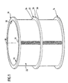
- Figures 1 and 2 show that the screen basket from three support rings 10, 12 and 14 as well as several profile bars 16 exists, the latter parallel to a sieve axis 18 run and the support rings in perpendicular to the sieve axis Levels.
- profile bars 16 so in the screen basket shown formed and arranged that the inlet side 20 for the Sorting fiber suspension on the inner circumference of the screen basket lies, the outlet side 22 for those let through the screen basket Fiber suspension on its outer circumference.
- everyone's particular identically designed support rings 10, 12 and 14 has one Cross section in the form of a flat rectangle and has one upper flat side 24, a lower flat side 26, an outer edge 28 and an inner edge 30.
- Fig. 3 shows a short section of a still straight Profile bar support 10 ', which later by bending to the closed support ring 10 is to be reshaped.
- the one Inner edge 30 of the support ring 10 corresponding first edge of the Profile bar support 10 ' was designated 30', the Outer edge 28 of the support ring 10 corresponding second edge of the Profile bar support 10 'with 28', and the visible in Fig. 3 upper flat side of the profile bar support was designated with 24 '.
- the profile bar support 10 ' a cutout 34, in which a profile rod 16 in the direction the longitudinal extension of the profile bar can be inserted. All cutouts 34 should have the same shape and the same dimensions have, and the same applies to the profile bars 16.
- the cross section of a profile bar is approximately mushroom-shaped a mushroom head forming a first cross-sectional end region 16A and a second cross-sectional end portion 16B forming roughly club-shaped mushroom foot, the shape of the second cross-sectional end portion 16B of the shape of the cutout 34 corresponds to, one sees proportionately low, in Fig. 3 recognizable play of the profile bar 16 in Section 34 from.
- the shape of the cutout 34 is now designed so that the cutout 34 is a constriction 34A has between the and the second edge 28 'of End of cutout 34 facing profile bar support 10 ' the latter forms an undercut 34B in the area thereof the edge of the cutout 34 has an approximately straight flank 34C has, with a designated in Fig. 3 at 40, perpendicular to the drawing level of FIG. 3 level forms an acute angle ⁇ , which is towards the second Edge 28 'of the profile bar support 10' opens.
- the closed support ring 10 plane 40 is a diameter plane of the strainer basket.
- the second cross-sectional end region 16B of the profiled bars 16 forms a protrusion 16C that fits into the undercut 34B of the associated cutout 34 engages so that before the deformation of the profile bar support 10 'according to the invention the profile rod 16 not according to FIG. 3 upwards from the cutout 34 can be pulled out.
- FIG. 3 leaves, the outer periphery of each profile bar 16th in the area of the second cross-sectional end area 16B of the profile bar even before the profile rod carrier is deformed according to the invention 10 'everywhere at least almost free of play against Edge of the assigned section 34 with the exception of one relatively narrow gap between the flank 34C of the Section 34 and the projection 16C of the profile bar.
- This Gap is caused by the deformation of the profile bar support according to the invention 10 'closed in the following way:
- a lower pressure roller 62 is pressed at the bottom (see FIG. 6), which around each other and to the flat sides of the profile bar support 10 'or the support ring 10 parallel axes 60' or 62 'are freely rotatable (the axes 60', 62 'also run perpendicular to the longitudinal direction of the section bar support 10 'or radial to the sieve axis 18).
- the pressure rollers 60 and 62 are under control or regulation of the pressure with which they according 6 in the vertical direction against the profile bar support 10 ' or the support ring 10 are pressed on all profile bars 16 passed along the profile bar support 10 'or around the Support ring 10 guided around and thus produce with their in Fig. 6th recognizable displacement ribs 60A and 62A on the upper and on the lower flat side of the profile bar support 10 'or Tragrings 10 (of course, the same applies accordingly to the Support ring 12 and the support ring 14) in the immediate vicinity the profile bars 16 each have a groove 70A and 70B and as a result of the design according to the invention which can be seen in FIG.
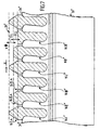
- FIG. 4 represents a section of FIG. 2 and do not show the profile bar support 10 ', but already the upper support ring 10, you can see that the profile bars 16 even after the profiled bars have been formed into closed ones
- Support rings between slot-shaped sieve openings Form 80, which run parallel to the sieve axis 18 and between the support rings 10, 12 and 12, 14 are open, respectively.
- the inlet side 20 communicates via the sieve openings 80 the outlet side 22 of the screen basket.
- the profile bars are in the first cross-sectional end regions 16A 16 on the sieve inlet side 20 with inclined flanks 82 and 84 and provided with rear flanks 86 and 88.
- the inclined flanks 82 and 84 form that which can be seen in FIG. 3
- Level 40 acute angles that are the same size or different and the rear flanks 86 and 88 lie in particular before carrying out the invention Deformation against the first edge 30 'of the profile bar support 10 'on.
- the inlet side is known 20 of the screen basket adjacent to a rotor in the to be sorted
- the first cross-sectional areas create fiber suspension 16A of the profile bars 16 in particular with their inclined Flanks 82 and 84 in the fiber suspension to be sorted Microturbulence, which is the formation of a significant Nonwoven fabric on the sieve inlet side 20 and a blockage counteract the screen openings 80.
- the second embodiment shown in Figures 7 to 9 differs from the first embodiment Figures 1 to 6 only in the design of the sieve outlet side turned away first long sides of the profile bars, namely in the design of the first cross-sectional areas of the profile bars with which the latter over those The edges of the support rings protrude from which the sieve inlet side are facing. Therefore, in Figures 7 to 9, as far possible, the same reference numerals are used as in the figures 1 to 6, but with the addition of two dashes.
- FIG. 7 is intended to be the illustration in FIG. 4 correspond, but with the modification that Fig. 7 none still shows straight beam, but the processing an annular support ring, which is consequently shown in Fig. 7 was shown as a straight element.
- a support ring 10 "holds a series of profile bars 16I", 16II “and 16III", which with their first cross-sectional end areas 16IA, 16IIA and 16IIIA protrude beyond the edge 30 "of the support ring 10" facing the sieve inlet side 20 "(see FIG 7).
- the Profile bars 16I “, 16II” and 16III “differ from each other essentially only in that the cross-sectional areas 16IA, 16IIA and 16IIIA formed series of profile bar sections against each other in the longitudinal direction of the bar are offset.
- the screen has several identical in the circumferential direction successive Profile bar groups, each of which groups is formed of three profile bars, namely a profile bar 16I ", one Profile bar 16II "and a profile bar 16III", which in the Sequence the order listed above.
- the arrow R was drawn, which should indicate the direction in which the to be sorted Fiber suspension flows along the inlet side 20 "of the sieve, in the case of a sorter with a rotor, the arrow R indicates but also the direction of rotation of the rotor, in particular that Direction, in the last or so-called cleaning wing of the rotor on the inlet side 20 "of the sieve.
- the first cross-sectional areas always in the order 16IIIA, 16IIA and 16IA on top of each other.
- the first cross-sectional end regions 16IA, 16IIA and 16IIIA protrude to different degrees into the fiber suspension to be sorted, ie they protrude differently beyond the inner edges 30 "of the support rings.
- the differences in the protrusions were shown in FIG D 1 and D 2 denote, where D 1 and D 2 can be of different sizes or of the same size - values of D 1 and D 2 of approximately the same size are preferred, particularly in the case of screen baskets for so-called pressure sorters, D 1 and D 2 are at most 1 mm, preferably 0.5 to 0.8 mm and in particular approximately 0.5 to approximately 0.6 mm.
- L 1 or L 2 or L 3 are the same size, which is to mean that the cross sections of the cross-sectional end regions 16IA, 16IIA and 1 6IIIA should not change over their axial length, which obviously does not necessarily have to be the case.
- L 1 or L 2 or L 3 is preferably approximately 15% to approximately 30% of the axial length of the sieve, in particular equal to 1/5 to 1/4 of the sieve length.
- L 1 or L 2 or L 3 is in a range from 150 to 200 mm.
- the different high or differently projecting cross-sectional end areas or profile bar sections 16IA, 16IIA and 16IIIA according to the invention arranged according to a special pattern such that one in Fig. 8 in the direction of arrow R on the sieve inlet side flowing, sorting fiber suspension a axial flow component or an enlarged axial flow component in the direction of the sieve axis, d. H. according to Fig.
Landscapes
- Chemical & Material Sciences (AREA)
- Chemical Kinetics & Catalysis (AREA)
- Engineering & Computer Science (AREA)
- Manufacturing & Machinery (AREA)
- Mechanical Engineering (AREA)
- Paper (AREA)
- Inorganic Fibers (AREA)
- Artificial Filaments (AREA)
- Nonwoven Fabrics (AREA)
Description
- Fig. 1
- eine perspektivische und weitgehend schematisierte Darstellung der ersten Ausführungsform des erfindungsgemäßen Stabsiebkorbs, welche nur einige wenige Profilstäbe erkennen läßt;
- Fig. 2
- eine Draufsicht auf den in Fig. 1 dargestellten Stabsiebkorb, wobei wiederum nur einige wenige Profilstäbe gezeichnet wurden;
- Fig. 3
- eine Draufsicht auf einen verhältnismäßig kurzen Abschnitt eines noch gestreckten bzw. geraden Profilstabträgers mit drei im Querschnitt gezeichneten Profilstäben, welche bereits in Ausschnitte des Profilstabträgers eingeschoben wurden, jedoch an letzterem noch nicht fixiert sind, d. h. also vor der erfindungsgemäßen plastischen Verformung des Profilstabträgers;
- Fig. 4
- eine der Fig. 3 entsprechende Darstellung, jedoch nach der erfindungsgemäßen plastischen Verformung des Profilstabträgers zwecks Verdrängung von Profilstabträgermaterial in Richtung auf die Profilstäbe;
- Fig. 5
- einen Schnitt nach der Linie 5-5 in Fig. 4;
- Fig. 6
- eine der Fig. 5 entsprechende Darstellung, jedoch samt zwei Walzwerkzeugen zur erfindungsgemäßen plastischen Verformung des Profilstabträgers;
- Fig. 7
- eine der Fig. 4 entsprechende Darstellung der zweiten Ausführungsform;
- Fig. 8
- einen Teil einer Abwicklung der zweiten Ausführungsform des erfindungsgemäßen Stabsiebkorbs, und zwar einer Ansicht seiner Einlaßseite gesehen in Richtung des Pfeils X aus Fig. 7, und
- Fig. 9
- eine Seitenansicht des über die Tragringe überstehenden Bereichs eines Profilstabs der zweiten Ausführungsform, gesehen in Richtung des Pfeils R aus Fig. 7, wobei jedoch nur ein Teil der Länge dieses Profilstabs dargestellt wurde.
Claims (37)
- Sieb für Fasersuspensionen mit einer bezüglich einer Siebachse (18) im wesentlichen rotationssymmetrischen Form, dessen eine, erste Umfangsseite eine Einlaßseite (20) und dessen andere, zweite Umfangsseite eine Auslaßseite (22) des Siebs für die Fasersuspension bildet, mit einer Serie von Profilstäben (16), welche sich quer zur Siebumfangsrichtung erstrecken, in Siebumfangsrichtung in gleichen Abständen voneinander angeordnet sind sowie zwischen sich schlitzförmige Sieböffnungen (80) bilden und deren Querschnitte jeweils eine längliche Form mit einem ersten, von der Siebauslaßseite abgekehrten Endbereich und einem zweiten, von der Siebeinlaßseite abgekehrten Endbereich besitzten, sowie mit wenigstens zwei in senkrecht zur Siebachse verlaufenden Ebenen liegenden und in Richtung der Siebachse im Abstand voneinander angeordneten Tragringen (10, 12, 14) aus plastisch verformbarem Material, von denen jeder in seinem der Siebeinlaßseite zugewandten ersten Randbereich eine Serie von der Siebeinlaßseite zu randoffenen Ausschnitten besitzt, deren Form - in Richtung der Siebachse gesehen - der Gestalt der in den Ausschnitten liegenden zweiten Querschnittendbereiche der Profilstäbe entspricht und in radialem Abstand von dem der Siebeinlaßseite zugekehrten, ersten Rand des Tragrings eine Hinterschneidung (34B) bildet, in welche ein Vorsprung des Profilstabquerschnitts eingreift, so daß die Profilstäbe mit ihren zweiten Querschnittendbereichen in bezüglich der Siebachse radialer Richtung sowie in Siebumfangsrichtung formschlüssig in den Tragringausschnitten gehalten sind, wobei die Profilstäbe in radialer Richtung über die ersten Ränder (30) der Tragringe überstehen und infolge einer plastischen Verformung der Tragringe mit ihren zweiten Querschnittendbereichen in den Tragringausschnitten eingespannt sind, dadurch gekennzeichnet, daß die Tragringe (10, 12, 14) auf der der Siebauslaßseite (22) zugewandten Seite der Profilstäbe (16) derart verformte Bereiche (70A, 70B, 72A, 72B) aufweisen, daß infolge einer Verdrängung von Tragringmaterial in Richtung auf die Siebeinlaßseite (20) die Profilstabvorsprünge (16C) in dieser Richtung gegen die Hinterschneidungen (34B) angepreßt sind.
- Sieb nach Anspruch 1, dadurch gekennzeichnet, daß die verformten Tragringbereiche (70A, 70B, 72A, 72B) eingepreßte Vertiefungen (70A, 70B) aufweisen.
- Sieb nach Anspruch 2, dadurch gekennzeichnet, daß die Vertiefungen die Gestalt von ringförmigen, um die Siebachse umlaufenden Rinnen (70A, 70B) besitzen.
- Sieb nach Anspruch 2 oder 3, dadurch gekennzeichnet, daß die Vertiefungen (70A, 70B) auf den den axialen Enden des Siebs zugekehrten Seiten (24, 26) der Tragringe (10, 12, 14) liegen.
- Sieb nach einem oder mehreren der vorstehenden Ansprüche, dadurch gekennzeichnet, daß die Tragringe (10, 12, 14) auf ihren beiden den axialen Siebenden zugekehrten Seiten (24, 26) mit verformten Bereichen (70A, 70B, 72A, 72B) versehen sind.
- Sieb nach Anspruch 5, dadurch gekennzeichnet, daß - in Richtung der Siebachse (18) - die verformten Bereiche (70A, 72A bzw. 70B, 72B) eines Tragrings (10, 12, 14) einander gegenüberliegen.
- Sieb nach einem oder mehreren der Ansprüche 3 bis 6, dadurch gekennzeichnet, daß die Rinnen (70A, 70B) gewalzte oder gerollte Bereiche sind.
- Sieb nach einem oder mehreren der vorstehenden Ansprüche, gekennzeichnet durch metallische Profilstäbe (16).
- Sieb nach einem oder mehreren der vorstehenden Ansprüche, dadurch gekennzeichnet, daß das Sieb zylindrisch ist.
- Sieb nach einem oder mehreren der vorstehenden Ansprüche, dadurch gekennzeichnet, daß die Innenumfangsseite des Siebs dessen Einlaßseite (20) bildet.
- Sieb nach einem oder mehreren der vorstehenden Ansprüche, dadurch gekennzeichnet, daß alle Profilstäbe (16) dieselbe Querschnittsform und alle Tragringausschnitte (34) dieselbe Gestalt besitzen.
- Sieb nach einem oder mehreren der vorstehenden Ansprüche, dadurch gekennzeichnet, daß die ersten Querschnittsendbereiche (16A) der Profilstäbe (16) derart gestaltet sind, daß sie in einer an der Siebeinlaßseite (20) umlaufenden Fasersuspension Mikroturbulenzen erzeugen.
- Sieb nach Anspruch 12, dadurch gekennzeichnet, daß die ersten Querschnittsendbereiche (16A) der Profilstäbe (16) gegenüber einer Durchmesserebene (40) des Siebs geneigte Flanken (82, 84) aufweisen, welche die Katheten eines zumindest ungefähr gleichschenkligen Dreiecks bilden, dessen Winkelhalbierende mindestens ungefähr in der besagten Durchmesserebene (40) liegt.
- Sieb nach einem oder mehreren der vorstehenden Ansprüche, dadurch gekennzeichnet, daß - in Richtung der Siebachse (18) gesehen - die Hinterschneidung (34B) der Tragringausschnitte (34) auf der der Siebauslaßseite (22) zugekehrten Seite der von der Hinterschneidung (34B) gebildeten Engstelle (34A) des Tragringausschnitts (34) eine Flanke (34C) bildet, welche gegenüber einer durch diese Engstelle hindurch verlaufenden Durchmesserebene (40) des Siebs um einen solchen spitzen, sich der Siebauslaßseite (22) zu öffnenden Winkel (α) geneigt ist, daß zwischen dieser Flanke (34C) und einer gegen letztere angepreßten Flanke des Profilstabvorsprungs (16C) Selbsthemmung gegeben ist.
- Sieb nach einem oder mehreren der vorstehenden Ansprüche, dadurch gekennzeichnet, daß der zweite Endbereich (16B) des Profilstabquerschnitts ungefähr keulenförmig gestaltet ist.
- Sieb nach einem oder mehreren der vorstehenden Ansprüche, dadurch gekennzeichnet, daß der erste Endbereich (16A) des Profilstabquerschnitts ungefähr pilzkopfförmig gestaltet ist mit der Siebauslaßseite (22) zugekehrten Flanken (86, 88), welche mit dem ersten Rand (30) des betreffenden Tragrings (10, 12, 14) zusammenwirkende Anschläge bilden.
- Sieb nach einem oder mehreren der vorstehenden Ansprüche, dadurch gekennzeichnet, daß die Tragringe (10, 12, 14) aus einem anderen Werkstoff bestehen als die Profilstäbe (16).
- Sieb nach Anspruch 17, dadurch gekennzeichnet, daß der Werkstoff der Profilstäbe (16) eine andere Festigkeit aufweist als der Tragringwerkstoff.
- Sieb nach Anspruch 18, dadurch gekennzeichnet, daß die Festigkeit des Profilstabwerkstoffs höher ist als die Festigkeit des Tragringwerkstoffs.
- Sieb nach einem der Ansprüche 1 bis 19, dadurch gekennzeichnet, daß in Siebumfangsrichtung (R) hintereinander angeordnete Profilstäbe (16I", 16II", 16III") an ihren von der Siebauslaßseite abgekehrten ersten Längsseiten derart unterschiedlich ausgebildet sind, daß die Profilstäbe einer an der Siebeinlaßseite (20") in Siebumfangsrichtung strömenden Fasersuspension eine in Richtung der Siebachse gerichtete axiale Strömungskomponente verleihen.
- Sieb nach Anspruch 20, dadurch gekennzeichnet, daß in Siebumfangsrichtung (R) jeweils unmittelbar aufeinanderfolgende Profilstäbe (16I", 16II", 16III") an ihren ersten Längsseiten mindestens in einem axialen Abschnitt des Siebs derart unterschiedlich ausgebildet sind, daß die Profilstäbe einer an der Siebeinlaßseite (20") in Siebumfangsrichtung strömenden Fasersuspension eine in Richtung der Siebachse gerichtete axiale Strömungskomponente verleihen.
- Sieb nach Anspruch 20 oder 21, dadurch gekennzeichnet, daß in Siebumfangsrichtung (R) mehrere identische Gruppen von Profilstäben (16I", 16II", 16III") aufeinanderfolgen, wobei sich die Profilstäbe einer Gruppe in der Ausbildung ihrer ersten Längsseiten voneinander unterscheiden.
- Sieb nach einem oder mehreren der Ansprüche 20 bis 22, dadurch gekennzeichnet, daß die Profilstäbe (16I", 16II", 16III") an ihren ersten Längsseiten abschnittsweise unterschiedlich weit über die ersten Tragringränder (30") überstehen.
- Sieb nach Anspruch 23, dadurch gekennzeichnet, daß jeder Profilstab (16I", 16II", 16III") eine sich in Stablängsrichtung periodisch wiederholende Serle von in Stablängsrichtung aufeinanderfolgenden Abschnitten (16IA, 16IIIA, 16IIA) unterschiedlichen Überstands aufweist.
- Sieb nach Anspruch 24, dadurch gekennzeichnet, daß die Serie von Profilstababschnitten (16IA, 16IIIA, 16IIA) bei jedem Profilstab dieselbe Anzahl von Profilstababschnitten umfaßt und die Überstände gleichartiger Profilstababschnitte identisch sind.
- Sieb nach Anspruch 25, dadurch gekennzeichnet, daß die in Stablängsrichtung gemessene Länge aller Profilstababschnitte (16IA, 16IIIA, 16IIA) identisch ist.
- Sieb nach den Ansprüchen 25 und 26, dadurch gekennzeichnet, daß In axialen Siebabschnitten, deren axiale Länge gleich derjenigen der Profilstababschnitte (16IA, 16IIIA, 16IIA) ist, in Siebumfangsrichtung (R) ungleichartige Profilstababschnitte aufeinanderfolgen.
- Sieb nach Anspruch 27, dadurch gekennzeichnet, daß in jedem axialen Siebabschnitt die Profilstababschnitte (16IA, 16IIIA, 16IIA) gegenüber gleichartigen Profilstababschnitten benachbarter axialer Siebabschnitte in Siebumfangsrichtung (R) derart versetzt angeordnet sind, daß die Profilstababschnitte einer an der Siebeinlaßseite (20") in Siebumfangsrichtung strömenden Fasersuspension eine in Richtung der Siebachse gerichtete axiale Strömungskomponente verleihen.
- Verfahren zur Herstellung eines Siebs für Fasersuspensionen mit einer bezüglich einer Siebachse im wesentlichen rotationssymmetrischen Form, dessen eine, erste Umfangsseite eine Einlaßseite und dessen andere, zweite Umfangsseite eine Auslaßseite des Siebs für die Fasersuspension bildet, mit einer Serie von Profilstäben, welche sich quer zur Siebumfangsrichtung erstrecken, in Siebumfangsrichtung in gleichen Abständen voneinander angeordnet sind sowie zwischen sich schlitzförmige Sieböffnungen bilden und deren Querschnitte jeweils eine längliche Form mit einem ersten, von der Siebauslaßseite abgekehrten Endbereich und einem zweiten, von der Siebeinlaßseite abgekehrten Endbereich besitzen, sowie mit wenigstens zwei in senkrecht zur Siebachse verlaufenden Ebenen liegenden und in Richtung der Siebachse im Abstand voneinander angeordneten ringförmigen Profilstabträgern aus plastisch verformbarem Material, von denen jeder in seinem der Siebeinlaßseite zugewandten ersten Randbereich eine Serie von der Siebeinlaßseite zu randoffenen Ausschnitten besitzt, deren Form - in Richtung der Siebachse gesehen - der Gestalt der in den Ausschnitten liegenden zweiten Querschnittendbereiche der Profilstäbe entspricht und in radialem Abstand von dem der Siebeinlaßseite zugekehrten, ersten Rand des Profilstabträgers eine Hinterschneidung bildet, in welche ein Vorsprung des Profilstabquerschnitts eingreift, so daß die Profilstäbe mit ihren zweiten Querschnittendbereichen in bezüglich der Siebachse radialer Richtung sowie in Siebumfangsrichtung formschlüssig in den Ausschnitten der Profilstabträger gehalten sind sowie mit ihren ersten Querschnittendbereichen in radialer Richtung über die ersten Ränder der Profilstabträger überstehen, wobei die Profilstabträger zunächst mit Ausschnitten versehen werden, welche etwas größer sind als die zweiten Querschnittendbereiche der Profilstäbe, worauf die Profilstäbe in die Profilstabträgerausschnitte eingesetzt und sodann durch eine plastische Verformung der Profilstabträger in deren Ausschnitten eingespannt werden, dadurch gekennzeichnet, daß die Profilstabträger auf der von ihren ersten Rändern abgewandten Seite der Profilstäbe derart plastisch verformt werden, daß infolge einer Verdrängung von Profilstabträgermaterial in Richtung auf die ersten Profilstabträgerränder die Profilstabvorsprünge in dieser Richtung gegen die Hinterschneidungen angepreßt werden.
- Verfahren nach Anspruch 29, dadurch gekennzeichnet, daß die Profilstabträger erst nach dem Einsetzen der Profilstäbe in die Profilstabträgerausschnitte zu geschlossenen Ringen gebogen werden.
- Verfahren nach Anspruch 29 oder 30, dadurch gekennzeichnet, daß die die Materialverdrängung bewirkende plastische Verformung der Profilstabträger an den ringförmigen Profilstabträgern vorgenommen wird.
- Verfahren nach einem oder mehreren der Ansprüche 29 bis 31, dadurch gekennzeichnet, daß die plastische Verformung mittels eines Druckwerkzeugs vorgenommen wird.
- Verfahren nach Anspruch 32, dadurch gekennzeichnet, daß zu der die Materialverdrängung bewirkenden plastischen Verformung eines Profilstabträgers dieser zwischen einer Druckrolle und einem Widerlager eingespannt sowie Druckrolle samt Widerlager und der Profilstabträger in Längsrichtung des letzteren so relativ zueinander bewegt werden, daß die Druckrolle alle Profilstäbe der Profilstabserie passiert.
- Verfahren nach Anspruch 33, dadurch gekennzeichnet, daß auch als Widerlager eine Druckrolle verwendet wird.
- Verfahren nach Anspruch 33 oder 34, dadurch gekennzeichnet, daß eine Druckrolle mit einem rippenförmigen Umfangsprofil verwendet wird.
- Verfahren nach einem oder mehreren der Ansprüche 29 bis 35, dadurch gekennzeichnet, daß durch die plastische Verformung in einer quer zur Profilstablängsrichtung verlaufenden Fläche des Profilstabträgers eine sich der ganzen Profilstabserie entlang erstreckende Rinne erzeugt wird.
- Verfahren nach Anspruch 36, dadurch gekennzeichnet, daß die Rinne so nahe bei den Profilstäben erzeugt wird, daß dabei verdrängtes Trägermaterial eine gegen die Profilstäbe anliegende Wulst bildet.
Applications Claiming Priority (3)
| Application Number | Priority Date | Filing Date | Title |
|---|---|---|---|
| DE19725737 | 1997-06-18 | ||
| DE19725737A DE19725737A1 (de) | 1997-06-18 | 1997-06-18 | Stabsiebkorb für Fasersuspensionen und Verfahren zu seiner Herstellung |
| PCT/EP1998/003574 WO1998057723A1 (de) | 1997-06-18 | 1998-06-13 | Stabsiebkorb für fasersuspensionen und verfahren zu seiner herstellung |
Publications (2)
| Publication Number | Publication Date |
|---|---|
| EP0989897A1 EP0989897A1 (de) | 2000-04-05 |
| EP0989897B1 true EP0989897B1 (de) | 2003-03-26 |
Family
ID=7832831
Family Applications (1)
| Application Number | Title | Priority Date | Filing Date |
|---|---|---|---|
| EP98934957A Expired - Lifetime EP0989897B1 (de) | 1997-06-18 | 1998-06-13 | Stabsiebkorb für fasersuspensionen und verfahren zu seiner herstellung |
Country Status (5)
| Country | Link |
|---|---|
| EP (1) | EP0989897B1 (de) |
| AT (1) | ATE235293T1 (de) |
| CA (1) | CA2293515C (de) |
| DE (2) | DE19725737A1 (de) |
| WO (1) | WO1998057723A1 (de) |
Families Citing this family (4)
| Publication number | Priority date | Publication date | Assignee | Title |
|---|---|---|---|---|
| CA2403127A1 (en) | 2000-02-19 | 2002-10-11 | Voith Finckh Fiber Systems Gmbh & Co. Kg | Sieve for fibre suspensions and a method for producing same |
| IT1315545B1 (it) * | 2000-11-13 | 2003-02-18 | Comer Spa | Metodo per la fabbricazione di cestelli filtranti per macchine difiltrazione di fibre in sospensione acquosa e cestello filtrante |
| DE102017127562A1 (de) * | 2017-11-22 | 2019-05-23 | Voith Patent Gmbh | Sieb |
| DE102018101666B3 (de) * | 2018-01-25 | 2018-09-20 | Voith Patent Gmbh | Siebzylinder |
Family Cites Families (5)
| Publication number | Priority date | Publication date | Assignee | Title |
|---|---|---|---|---|
| DE3927748C2 (de) * | 1989-08-23 | 1994-03-10 | Voith Gmbh J M | Verfahren zum Herstellen eines Siebkorbes sowie nach diesem Verfahren hergestellter Siebkorb |
| SE466706B (sv) * | 1990-07-20 | 1992-03-23 | Kamyr Ab | Vaeggorgan foer separering av vaetska fraan ett vaetskehaltigt partikelmaterial |
| DE4104615A1 (de) * | 1991-02-15 | 1992-08-20 | Voith Gmbh J M | Siebkorb |
| US5394600A (en) * | 1994-02-14 | 1995-03-07 | Chen; Chao-Ho | Method for making a screen |
| DE19625726C1 (de) * | 1996-06-27 | 1997-06-12 | Voith Sulzer Stoffaufbereitung | Siebvorrichtung mit spaltförmigen Öffnungen |
-
1997
- 1997-06-18 DE DE19725737A patent/DE19725737A1/de not_active Withdrawn
-
1998
- 1998-06-13 EP EP98934957A patent/EP0989897B1/de not_active Expired - Lifetime
- 1998-06-13 CA CA002293515A patent/CA2293515C/en not_active Expired - Fee Related
- 1998-06-13 DE DE59807654T patent/DE59807654D1/de not_active Expired - Lifetime
- 1998-06-13 AT AT98934957T patent/ATE235293T1/de not_active IP Right Cessation
- 1998-06-13 WO PCT/EP1998/003574 patent/WO1998057723A1/de not_active Ceased
Also Published As
| Publication number | Publication date |
|---|---|
| WO1998057723A1 (de) | 1998-12-23 |
| DE19725737A1 (de) | 1998-12-24 |
| ATE235293T1 (de) | 2003-04-15 |
| CA2293515C (en) | 2004-06-22 |
| CA2293515A1 (en) | 1998-12-23 |
| EP0989897A1 (de) | 2000-04-05 |
| DE59807654D1 (de) | 2003-04-30 |
Similar Documents
| Publication | Publication Date | Title |
|---|---|---|
| DE69608109T2 (de) | Sieb und verfahren zur herstellung | |
| EP1297218B1 (de) | Sieb für fasersuspensionen sowie verfahren zu seiner herstellung | |
| DE69615414T2 (de) | Siebvorrichtung wie ein siebzylinder, und verfahren zur herstellung der siebvorrichtung | |
| EP0499154B1 (de) | Siebkorb | |
| EP0523313B1 (de) | Siebelement | |
| DE9219128U1 (de) | Sägeblatt | |
| EP0316570A2 (de) | Siebkorb und Verfahren zu dessen Herstellung | |
| DE19635189C2 (de) | Verfahren zur Herstellung von Sieben | |
| EP0808941A1 (de) | Verfahren zur Herstellung einer Siebvorrichtung mit spaltförmigen Öffnungen sowie danach hergestellte Siebvorrichtung | |
| DE19651643A1 (de) | Siebvorrichtung mit spaltförmigen Öffnungen | |
| EP0567726B1 (de) | Siebvorrichtung | |
| EP0043868B1 (de) | Zum Verbinden mit den Deckelstäben einer Karde bestimmter Kratzenbeschlag | |
| DE9108129U1 (de) | Siebelement | |
| EP0989897A1 (de) | Stabsiebkorb für fasersuspensionen und verfahren zu seiner herstellung | |
| DE102008033794A1 (de) | Vorrichtung zum Stauchkräuseln von synthetischen Fasersträngen | |
| EP3790669B1 (de) | Siebvorrichtung | |
| EP3714099A1 (de) | Sieb | |
| DE3015370C2 (de) | Siebkorb für Sortierer der Papierindustrie | |
| DE19709582C2 (de) | Verfahren zur Herstellung einer Siebvorrichtung mit spaltförmigen Öffnungen | |
| DE19625726C1 (de) | Siebvorrichtung mit spaltförmigen Öffnungen | |
| DE19836316C2 (de) | Verfahren zur Herstellung von gewölbten Sieben | |
| EP3941648B1 (de) | Siebherstellverfahren | |
| DE19635156C2 (de) | Verfahren zur Herstellung von Sieben | |
| AT400853B (de) | Sieb für papierzellstoff-splitterfänger und klassierer | |
| DE10247166A1 (de) | Verfahren zur Herstellung einer Siebvorrichtung mit schlitzförmigen Öffnungen |
Legal Events
| Date | Code | Title | Description |
|---|---|---|---|
| PUAI | Public reference made under article 153(3) epc to a published international application that has entered the european phase |
Free format text: ORIGINAL CODE: 0009012 |
|
| 17P | Request for examination filed |
Effective date: 19990917 |
|
| AK | Designated contracting states |
Kind code of ref document: A1 Designated state(s): AT CH DE FI FR GB LI SE |
|
| 17Q | First examination report despatched |
Effective date: 20010502 |
|
| GRAG | Despatch of communication of intention to grant |
Free format text: ORIGINAL CODE: EPIDOS AGRA |
|
| GRAG | Despatch of communication of intention to grant |
Free format text: ORIGINAL CODE: EPIDOS AGRA |
|
| GRAH | Despatch of communication of intention to grant a patent |
Free format text: ORIGINAL CODE: EPIDOS IGRA |
|
| GRAH | Despatch of communication of intention to grant a patent |
Free format text: ORIGINAL CODE: EPIDOS IGRA |
|
| RAP1 | Party data changed (applicant data changed or rights of an application transferred) |
Owner name: VOITH PAPER PATENT GMBH |
|
| GRAA | (expected) grant |
Free format text: ORIGINAL CODE: 0009210 |
|
| AK | Designated contracting states |
Designated state(s): AT CH DE FI FR GB LI SE |
|
| REG | Reference to a national code |
Ref country code: GB Ref legal event code: FG4D Free format text: NOT ENGLISH |
|
| REG | Reference to a national code |
Ref country code: CH Ref legal event code: EP |
|
| REG | Reference to a national code |
Ref country code: CH Ref legal event code: NV Representative=s name: ISLER & PEDRAZZINI AG |
|
| REF | Corresponds to: |
Ref document number: 59807654 Country of ref document: DE Date of ref document: 20030430 Kind code of ref document: P |
|
| GBT | Gb: translation of ep patent filed (gb section 77(6)(a)/1977) | ||
| REG | Reference to a national code |
Ref country code: SE Ref legal event code: TRGR |
|
| ET | Fr: translation filed | ||
| PLBE | No opposition filed within time limit |
Free format text: ORIGINAL CODE: 0009261 |
|
| STAA | Information on the status of an ep patent application or granted ep patent |
Free format text: STATUS: NO OPPOSITION FILED WITHIN TIME LIMIT |
|
| 26N | No opposition filed |
Effective date: 20031230 |
|
| REG | Reference to a national code |
Ref country code: CH Ref legal event code: PCAR Free format text: ISLER & PEDRAZZINI AG;POSTFACH 1772;8027 ZUERICH (CH) |
|
| PGFP | Annual fee paid to national office [announced via postgrant information from national office to epo] |
Ref country code: FR Payment date: 20100706 Year of fee payment: 13 Ref country code: FI Payment date: 20100615 Year of fee payment: 13 |
|
| PGFP | Annual fee paid to national office [announced via postgrant information from national office to epo] |
Ref country code: AT Payment date: 20100614 Year of fee payment: 13 |
|
| PGFP | Annual fee paid to national office [announced via postgrant information from national office to epo] |
Ref country code: CH Payment date: 20100623 Year of fee payment: 13 |
|
| PGFP | Annual fee paid to national office [announced via postgrant information from national office to epo] |
Ref country code: SE Payment date: 20100614 Year of fee payment: 13 Ref country code: GB Payment date: 20100618 Year of fee payment: 13 Ref country code: DE Payment date: 20100625 Year of fee payment: 13 |
|
| PG25 | Lapsed in a contracting state [announced via postgrant information from national office to epo] |
Ref country code: FI Free format text: LAPSE BECAUSE OF NON-PAYMENT OF DUE FEES Effective date: 20110613 |
|
| REG | Reference to a national code |
Ref country code: CH Ref legal event code: PL |
|
| REG | Reference to a national code |
Ref country code: SE Ref legal event code: EUG |
|
| GBPC | Gb: european patent ceased through non-payment of renewal fee |
Effective date: 20110613 |
|
| PG25 | Lapsed in a contracting state [announced via postgrant information from national office to epo] |
Ref country code: AT Free format text: LAPSE BECAUSE OF NON-PAYMENT OF DUE FEES Effective date: 20110613 |
|
| REG | Reference to a national code |
Ref country code: AT Ref legal event code: MM01 Ref document number: 235293 Country of ref document: AT Kind code of ref document: T Effective date: 20110613 |
|
| REG | Reference to a national code |
Ref country code: FR Ref legal event code: ST Effective date: 20120229 |
|
| REG | Reference to a national code |
Ref country code: DE Ref legal event code: R119 Ref document number: 59807654 Country of ref document: DE Effective date: 20120103 |
|
| PG25 | Lapsed in a contracting state [announced via postgrant information from national office to epo] |
Ref country code: FR Free format text: LAPSE BECAUSE OF NON-PAYMENT OF DUE FEES Effective date: 20110630 Ref country code: DE Free format text: LAPSE BECAUSE OF NON-PAYMENT OF DUE FEES Effective date: 20120103 Ref country code: LI Free format text: LAPSE BECAUSE OF NON-PAYMENT OF DUE FEES Effective date: 20110630 Ref country code: CH Free format text: LAPSE BECAUSE OF NON-PAYMENT OF DUE FEES Effective date: 20110630 |
|
| PG25 | Lapsed in a contracting state [announced via postgrant information from national office to epo] |
Ref country code: GB Free format text: LAPSE BECAUSE OF NON-PAYMENT OF DUE FEES Effective date: 20110613 |
|
| PG25 | Lapsed in a contracting state [announced via postgrant information from national office to epo] |
Ref country code: SE Free format text: LAPSE BECAUSE OF NON-PAYMENT OF DUE FEES Effective date: 20110614 |