EP0989729A2 - Image input system, its control method, and storage medium - Google Patents
Image input system, its control method, and storage medium Download PDFInfo
- Publication number
- EP0989729A2 EP0989729A2 EP99118642A EP99118642A EP0989729A2 EP 0989729 A2 EP0989729 A2 EP 0989729A2 EP 99118642 A EP99118642 A EP 99118642A EP 99118642 A EP99118642 A EP 99118642A EP 0989729 A2 EP0989729 A2 EP 0989729A2
- Authority
- EP
- European Patent Office
- Prior art keywords
- image input
- input device
- computer
- software
- image
- Prior art date
- Legal status (The legal status is an assumption and is not a legal conclusion. Google has not performed a legal analysis and makes no representation as to the accuracy of the status listed.)
- Granted
Links
- 238000000034 method Methods 0.000 title claims description 42
- 230000008569 process Effects 0.000 claims description 27
- 230000015572 biosynthetic process Effects 0.000 claims description 24
- 238000003786 synthesis reaction Methods 0.000 claims description 10
- 230000006870 function Effects 0.000 description 19
- 238000012546 transfer Methods 0.000 description 10
- 238000004891 communication Methods 0.000 description 3
- 238000012545 processing Methods 0.000 description 3
- 230000007246 mechanism Effects 0.000 description 2
- 238000001454 recorded image Methods 0.000 description 2
- 230000005540 biological transmission Effects 0.000 description 1
- 238000012986 modification Methods 0.000 description 1
- 230000004048 modification Effects 0.000 description 1
- 230000003287 optical effect Effects 0.000 description 1
- 230000004044 response Effects 0.000 description 1
- 229910052709 silver Inorganic materials 0.000 description 1
- 239000004332 silver Substances 0.000 description 1
- -1 silver halide Chemical class 0.000 description 1
Images




Classifications
-
- H—ELECTRICITY
- H04—ELECTRIC COMMUNICATION TECHNIQUE
- H04N—PICTORIAL COMMUNICATION, e.g. TELEVISION
- H04N1/00—Scanning, transmission or reproduction of documents or the like, e.g. facsimile transmission; Details thereof
- H04N1/00127—Connection or combination of a still picture apparatus with another apparatus, e.g. for storage, processing or transmission of still picture signals or of information associated with a still picture
- H04N1/00204—Connection or combination of a still picture apparatus with another apparatus, e.g. for storage, processing or transmission of still picture signals or of information associated with a still picture with a digital computer or a digital computer system, e.g. an internet server
-
- H—ELECTRICITY
- H04—ELECTRIC COMMUNICATION TECHNIQUE
- H04N—PICTORIAL COMMUNICATION, e.g. TELEVISION
- H04N2201/00—Indexing scheme relating to scanning, transmission or reproduction of documents or the like, and to details thereof
- H04N2201/0008—Connection or combination of a still picture apparatus with another apparatus
- H04N2201/0013—Arrangements for the control of the connected apparatus by the still picture apparatus
Definitions
- the present invention relates to a system which connects an image input device such as a digital camera having a plurality of operation modes, and an image processing apparatus such as a personal computer or the like, and inputs and saves images, its control method, and a storage medium.
- an image input device such as a digital camera having a plurality of operation modes
- an image processing apparatus such as a personal computer or the like
- an RS-232C serial cable is prevalently used as an I/F for connecting a personal computer and camera.
- This I/F has high compatibility, i.e., is supported by all personal computers, but has low transfer rate.
- image input software such as a TWAIN driver or the like has a fixed procedure for transferring thumbnail data with a small data size first to display image indices in the camera, and then transferring only original images selected by the user.
- USB Universal Serial Bus
- STI Silicon Image Captures Architecture and Interfaces
- USB can implement hot plugin (a USB device can be plugged or unplugged while a PC is running, and the OS can recognize the plugged or unplugged state), and a mechanism for automatically recognizing the connected camera, and automatically starting a predetermined application associated with the camera by the STI can be provided.
- hot plugin a USB device can be plugged or unplugged while a PC is running, and the OS can recognize the plugged or unplugged state
- a mechanism for automatically recognizing the connected camera, and automatically starting a predetermined application associated with the camera by the STI can be provided.
- the STI has a mechanism for starting corresponding PC software in response to connection of a camera as a trigger. Hence, tedious operation can be greatly reduced, and it is easy even for a novice user of the personal computer to use such system.
- the STI architecture considers the TWAIN driver as main image input software, and suffers the following shortcomings:
- the digital camera has not only a function of sensing an image, playing back the sensed image on its LCD, and transferring the image to the PC, but also more functions.
- the number of functions of the digital camera is increasing. For example, the following functions falling outside the range of a function of merely capturing a sensed image into a PC are available:
- the present invention has been made in consideration of the above-mentioned problems, and has as its object to provide an image input system which is easy to use, its control method, and a storage medium.
- an image input system is characterized by the following arrangement according to its first aspect.
- an image input system comprising an image input device having a plurality of operation modes, and a computer having a plurality of software programs corresponding to the plurality of operation modes, wherein when the image input device is connected to the computer, when a power supply of the image input device is turned on after the image input device is connected to the computer, or when the image input device is switched to another operation mode while the image input device is connected to the computer, the software program corresponding to the operation mode of the image input device is automatically started.
- An image input system is characterized by the following arrangement according to its second aspect.
- an image input system comprising an image input device having a plurality of operation modes, and a computer having a single software program which has a plurality of modes corresponding to the plurality of operation modes, wherein when the image input device is connected to the computer, when a power supply of the image input device is turned on after the image input device is connected to the computer, or when the image input device is switched to another operation mode while the image input device is connected to the computer, that one of the plurality of modes of the software in the computer, which corresponds to the operation mode of the image input device, is automatically started.
- a method of controlling an image input system according to the present invention is characterized by the following arrangement according to its first aspect.
- a method of controlling an image input system which comprises an image input device having a plurality of operation modes, and a computer having a plurality of software programs corresponding to the plurality of operation modes, comprising the step of automatically starting the software program corresponding to the operation mode of the image input device, when the image input device is connected to the computer, when a power supply of the image input device is turned on after the image input device is connected to the computer, or when the image input device is switched to another operation mode while the image input device is connected to the computer.
- a method of controlling an image input system according to the present invention is characterized by the following arrangement according to its second aspect.
- a method of controlling an image input system which comprises an image input device having a plurality of operation modes, and a computer having a single software program which has a plurality of modes corresponding to the plurality of operation modes, comprising the step of automatically starting that one of the plurality of modes of the software in the computer, which corresponds to the operation mode of the image input device when the image input device is connected to the computer, when a power supply of the image input device is turned on after the image input device is connected to the computer, or when the image input device is switched to another operation mode while the image input device is connected to the computer.
- a storage medium according to the present invention is characterized by the following arrangement according to its first aspect.
- a storage medium that stores a control program for controlling an image input system, which comprises an image input device having a plurality of operation modes, and a computer having a plurality of software programs corresponding to the plurality of operation modes, the control program comprising a code of the step of automatically starting the software program corresponding to the operation mode of the image input device, when the image input device is connected to the computer, when a power supply of the image input device is turned on after the image input device is connected to the computer, or when the image input device is switched to another operation mode while the image input device is connected to the computer.
- a storage medium according to the present invention is characterized by the following arrangement according to its second aspect.
- a storage medium that stores a control program for controlling an image input system, which comprises an image input device having a plurality of operation modes, and a computer having a single software program which has a plurality of modes corresponding to the plurality of operation modes, the control program comprising a code of the step of automatically starting that one of the plurality of modes of the software in the computer, which corresponds to the operation mode of the image input device when the image input device is connected to the computer, when a power supply of the image input device is turned on after the image input device is connected to the computer, or when the image input device is switched to another operation mode while the image input device is connected to the computer.
- an application corresponding to the mode set in the camera is started, is connected to the camera, and automatically executes a predetermined process.
- the application is automatically disconnected from the camera, and automatically ends depending on its type or setups, and an application corresponding to the selected mode is started and is connected to the camera to execute predetermined operation.
- the mode includes the image sensing mode, playback mode, slideshow mode, stitch assist mode, and the like, that have already been described in the paragraphs of the prior art, and these modes can be set using a mode dial switch and push switches of the camera main body, menu items displayed on an LCD panel of the camera, and the like.
- Fig. 1 shows a digital camera used in the first embodiment.
- reference numeral 1 denotes a USB I/F which is connected to the PC.
- Reference numeral 2 denotes a mode dial switch which has a playback (Play) mode 2a, image sensing (Rec) mode 2b, stitch assist (Stitch) mode 2c, slideshow playback (Slide) mode 2d, and power OFF 2e.
- Reference numeral 3 denotes a CF (Compact FlashTM) card slot.
- the selected mode is started simultaneously.
- a preview image is displayed on an LCD 4, and an image is sensed by pressing a release switch 5 and is stored in a CF card 6.
- the latest sensed and recorded image is displayed on the LCD 4, and other recorded images are played back in turn by + and - buttons 7a and 7b.
- the already sensed image is displayed on one side 4a of the LCD 4, and a preview image is displayed on the other side 4b and can be sensed.
- images recorded in the camera are played back on the LCD 4 or on a TV via a video output 8 at predetermined time intervals.
- the displayed image can be switched to the next or previous one using the + and - buttons 7a and 7b.
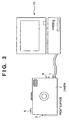
- Fig. 3 shows a state wherein the camera and PC are connected via USB.
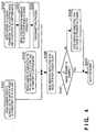
- the camera is connected to the PC and can communicate with it in three states shown in Fig. 4.
- the camera is connected to the PC via USB while its power switch is ON and a given mode is selected (a mode set by the setting position of, e.g., the mode dial switch) (step S401).
- a given mode is selected (a mode set by the setting position of, e.g., the mode dial switch) (step S401).
- the camera sends a message indicating the mode in which the camera is set currently to the PC at a timing that it detects connection to USB (step S406).
- the camera is connected to USB while its power switch is OFF, and after that, the power switch is turned on. At this time, the camera also sends a message indicating the mode in which the camera is set currently to the PC in accordance with the set mode (step S406).
- the camera has already been set in a given mode, the corresponding application has already been started, and the camera and application are connected and communicate with each other.
- the camera sends a disconnection message to the connected application at that timing to disconnect the communication with the application (step S405).
- a message indicating a new mode in which the camera is set currently is sent to the PC (step S406).
- the camera checks if sensed images are present in the camera (step S407). If no images are present, the camera also sends a message indicating that no images are present in the camera (step S408).
- the aforementioned process is executed first when the camera and PC are connected, and an associated application is started.
- the STI starts an associated application in correspondence with the message of each mode.
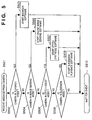
- Fig. 5 shows this process.
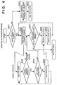
- Fig. 6 shows operation automatically executed when the browser software associated with the playback mode is started.
- step S601 It is checked in step S601 if images are present in the camera. This checking step is attained by checking if the message issued in step S408 in Fig. 4 has arrived at the PC. If this message has arrived, the browser software displays a message indicating no image (step S602), and ends itself (step S603).
- the browser software sends an image transfer request to the camera in step S604.
- the camera checks if the received message is an image transfer request (step S605), and then checks if all images have already been transferred (step S606). If images to be transferred still remain, the camera sends image data to the browser software in step S608.
- the browser software receives the image data in step S609, and displays that image data on the PC screen in step S610.
- all image data in the camera can be automatically loaded from the camera and can be displayed on the PC. From the viewpoint of user operation, all images in the camera can be automatically displayed on the PC by only setting the mode dial switch 2 at the playback mode 2a.
- the camera sends a corresponding message to the browser software.
- the browser software executes a process for disconnecting the communication with the camera, and then executes one of the following three options.
- the first option automatically ends the browser software
- the second option displays a message indicating that the connection with the camera is disconnected by user operation to the user, and prompts the user to select whether the browser software is to end or continue
- the third option continues to run the browser software.
- These options can be selected from a setup menu of the browser software.
- the second option that prompts the user to select whether the browser software is to end or continue is preferably set.
- FIG. 8 shows an example of the on-line image sensing software.
- An image which is being currently seen by the camera is displayed on a preview area 802 in a window 801 as a preview image.
- the camera senses the image, and sensed image data is displayed on a window 804.
- the sensed image data can be saved as an image file.
- Fig. 7 is a flow chart showing operation executed when the on-line image sensing software is started.
- the on-line image sensing software When the mode dial switch 2 is set at the Rec mode 2b, the on-line image sensing software is automatically started.
- the on-line image sensing software sends a reduced-scale image transmission request to the camera (step S701).
- This reduced-scale image is to be displayed on the preview area 802.
- a reduced-scale image is requested in place of a full-size image which is equal to the sensed image size.
- step S703 the camera sends reduced-scale image data (step S703).
- the on-line image sensing software receives that image data in step S704. and displays the received data on the preview area 802 in step S705.
- a preview image which is being currently sensed by the camera is displayed as a moving image on the preview area 802.
- step S707 When the user has pressed the image sensing button 803, the control leaves the loop based on the checking result in step S706, and a sensed image transfer request is sent in step S707.
- the camera Upon receiving this message (step S708), the camera senses an image, and sends sensed full-size image data in step S709.
- the on-line image sensing software receives this image data in step S710, and displays it on the window 804 in Fig. 8 in step S711.
- the user can automatically preview an image on-line by only setting the mode dial switch 2 at the Rec mode 2b, and can sense that image by pressing the image sensing button on the PC.
- the camera sends a corresponding message to the on-line image sensing software.
- the on-line image sensing software executes a process for disconnecting the communication with the camera, and then automatically ends itself.
- the aforementioned browser software has options for selecting, e.g., whether or not the software continues to run, but such options are not available for this software. This is because the on-line image sensing software does not function at all unless it is connected to the camera.
- step S901 It is checked in step S901 if images are present in the camera. This checking step is attained by checking if the message issued in step S408 in Fig. 4 has arrived at the PC. If this message has arrived, the stitch synthesis software displays a message indicating that no images are stored in the camera (step S902), and ends (step S903).
- the stitch synthesis software sends a transfer request of images sensed in the stitch assist mode to the camera in step S904. Upon receiving this request, the camera checks if all stitch assist images have already been transferred (step S905). If stitch assist image to be transferred still remain, image data is transferred to the stitch synthesis software in step S907.
- the stitch synthesis software receives this image data in step S908, and saves that image data in a file in step S909. By repeating these steps, all stitch assist image data in the camera can be automatically loaded from the camera. After that, the saved stitch assist images are read out, and a process for stitching these images to obtain a single synthesis image is executed in step S910.
- images can be sensed in the stitch assist mode by setting the mode dial switch 2 at the stitch assist mode 2c, and all the stitch assist images in the camera can be automatically loaded into the PC and can be synthesized by only connecting the camera to the PC.
- the camera sends a corresponding message to the stitch synthesis software.
- the stitch synthesis software disconnects the connection with the camera. In this case, if all the stitch assist images in the camera have already been loaded, the stitch synthesis software continues a synthesis process. However, if all the images have not been loaded yet, the stitch synthesis software automatically ends itself since it cannot execute a synthesis process.
- step S1001 It is checked in step S1001 if images are present in the camera. This checking step is attained by checking if the message issued in step S408 in Fig. 4 has arrived at the PC. If this message has arrived, the slideshow playback software displays a message indicating that no images are stored in the camera (step S1002), and ends itself (step S1003).
- the slideshow playback software sends an image transfer request to the camera in step S1004.
- the camera checks if all images have already been transferred (step S1005).
- image data is sent to the slideshow playback software in step S1007.
- the slideshow playback software receives the image data in step S1008, and saves that image data in a file in step S1009.
- step S1010 all image data in the camera can be loaded from the camera. After that, the saved images are read out, and slideshow playback of these images is executed on the PC screen in step S1010.
- all images in the camera can be automatically loaded and can be played back as a slideshow by only setting the mode dial switch 2 at the slideshow mode 2d.
- the camera sends a corresponding message to the slideshow playback software.
- the slideshow playback software disconnects the connection with the camera. In this case, if all the images in the camera have already been loaded, the slideshow playback software continues slideshow playback. However, if all the images have not been loaded yet, the slideshow playback software automatically ends itself since it cannot execute slideshow playback.
- different software programs are started in correspondence with the operation modes of the camera.
- a single software program is started in an operation mode corresponding to the operation mode of the camera.
- the software is started in different modes in correspondence with the operation modes of the camera.
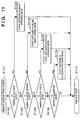
- step S1102 If it is determined in step S1102 that the camera is in the playback mode, the software is started in an image browsing mode in step S1103.
- the subsequent operation is the same as that described in the first embodiment.
- step S1104 If it is determined in step S1104 that the camera is in the image sensing mode, the software is started in an on-line image sensing mode in step S1105.
- the subsequent operation is the same as that described in the first embodiment.
- step S1106 If it is determined in step S1106 that the camera is in the stitch assist mode, the software is started in a stitch synthesis mode in step S1107.
- the subsequent operation is the same as that described in the first embodiment.
- step S1108 If it is determined in step S1108 that the camera is in the slideshow mode, the software is started in a slideshow playback mode in step S1109.
- the subsequent operation is the same as that described in the first embodiment.
- the objects of the present invention are also achieved by supplying a storage medium, which records a program code of a software program that can implement the functions of the above-mentioned embodiments to the system or apparatus, and reading out and executing the program code stored in the storage medium by a computer (or a CPU or MPU) of the system or apparatus.
- the program code itself read out from the storage medium implements the functions of the above-mentioned embodiments, and the storage medium which stores the program code constitutes the present invention.
- the storage medium for supplying the program code for example, a floppy disk, hard disk, optical disk, magneto-optical disk, CD-ROM, CD-R, magnetic tape, nonvolatile memory card, ROM, and the like may be used.
- the functions of the above-mentioned embodiments may be implemented not only by executing the readout program code by the computer but also by some or all of actual processing operations executed by an OS (operating system) running on the computer on the basis of an instruction of the program code.
- OS operating system
- the functions of the above-mentioned embodiments may be implemented by some or all of actual processing operations executed by a CPU or the like arranged in a function extension board or a function extension unit, which is inserted in or connected to the computer, after the program code read out from the storage medium is written in a memory of the extension board or unit.
- a software program can be automatically started in correspondence with the mode set in the camera.
- a software program can be started in a software mode corresponding to the mode set in the camera.
- an image input system has an image input device (camera) having a plurality of operation modes, and a computer having a plurality of software programs corresponding to the plurality of operation modes, and when the image input device is connected to the computer, when a power supply of the image input device is turned on after the image input device is connected to the computer, or when the image input device is switched to another operation mode while the image input device is connected to the computer, the software program corresponding to the operation mode of the image input device is automatically started.
- an image input device camera
- a computer having a plurality of software programs corresponding to the plurality of operation modes
Landscapes
- Engineering & Computer Science (AREA)
- Computing Systems (AREA)
- General Engineering & Computer Science (AREA)
- Multimedia (AREA)
- Signal Processing (AREA)
- Studio Devices (AREA)
- Image Input (AREA)
- Processing Or Creating Images (AREA)
Abstract
Description
- The present invention relates to a system which connects an image input device such as a digital camera having a plurality of operation modes, and an image processing apparatus such as a personal computer or the like, and inputs and saves images, its control method, and a storage medium.
- Conventionally, when an image captured by a digital camera is input to a personal computer, the following procedure is required:
- 1. The camera is connected to the personal computer via a serial cable.
- 2. The user starts an application.
- 3. A TWAIN driver is started from the application.
- 4. A button or menu command for connecting the camera is pressed.
- 5. Thumbnails of images in the camera are displayed on the window of the TWAIN driver.
- 6. The user selects an image to be captured into the personal computer and presses a capture button.
- 7. The selected image is transferred to the personal computer.
-
- In this manner, in order to capture an image in the digital camera into the personal computer, a given procedure is required, and the user must have certain knowledge. Recently, an RS-232C serial cable is prevalently used as an I/F for connecting a personal computer and camera. This I/F has high compatibility, i.e., is supported by all personal computers, but has low transfer rate. With the use of this I/F, the configuration of image input software such as a TWAIN driver or the like has a fixed procedure for transferring thumbnail data with a small data size first to display image indices in the camera, and then transferring only original images selected by the user.
- However, Microsoft Windows98™ formally supports USB (Universal Serial Bus) as a new I/F, and STI (Still Image Captures Architecture and Interfaces) is prepared as a software I/F for digital cameras. USB has a maximum transfer rate of 10 Mbps; an original image can be directly transferred without making the user feel stress as long as it is a compressed file such as a JPEG file or the like. In this manner, an environment for allowing to readily build image input software with a higher degree of freedom without fixing the procedure to that for displaying thumbnails and then transferring only a required original image is in order.
- USB can implement hot plugin (a USB device can be plugged or unplugged while a PC is running, and the OS can recognize the plugged or unplugged state), and a mechanism for automatically recognizing the connected camera, and automatically starting a predetermined application associated with the camera by the STI can be provided. As can be seen from the above description, an image can be captured from the camera to the personal computer by the following procedure:
- (1) The camera is connected.
- (2) The associated application is automatically started. The application automatically starts a corresponding TWAIN driver, which automatically connects the camera and displays thumbnails in the camera.
- (3) The user selects an image to be captured and presses a capture button.
- (4) The selected image is transferred to the
personal computer.
In this manner,steps 2. to 5. in the above procedure can be automated. -
- The STI has a mechanism for starting corresponding PC software in response to connection of a camera as a trigger. Hence, tedious operation can be greatly reduced, and it is easy even for a novice user of the personal computer to use such system.
- However, the STI architecture considers the TWAIN driver as main image input software, and suffers the following shortcomings:
- (1) The number of types of applications that can be associated is only one, and the application which runs upon connecting a camera is fixed.
- (2) The associated application starts a TWAIN driver corresponding to the camera.
- (3) Starting the TWAIN driver means that the application cannot be basically used for purposes other than that for capturing an image into the personal computer.
-
- On the other hand, the digital camera has not only a function of sensing an image, playing back the sensed image on its LCD, and transferring the image to the PC, but also more functions. The number of functions of the digital camera is increasing. For example, the following functions falling outside the range of a function of merely capturing a sensed image into a PC are available:
- (1) Slideshow function: All or selected images in the camera are automatically played back on the camera LCD or on a TV via the video output at predetermined time intervals.
- (2) On-line image sensing function: An image is previewed on PC software while the PC is connected to the camera. By pressing an image sensing button of that camera or on PC software, the camera senses the previewed image, and automatically transfers the sensed image to the PC. This function become actually usable after USB is supported as a standard I/F. The conventional RS232C can only preview an image for about one frame per sec in a size as small as a thumbnail image, and is not practical.
- (3) Divided image synthesis function: In order
to sense a panoramic image which cannot be sensed by
single image sensing, image sensing is divisionally
done a plurality of number of times. These images are
automatically stitched by PC synthesis software (to be
referred to as stitch synthesis software hereinafter)
to form a panoramic image. Upon synthesis, since a
common region in neighboring images is detected to
automatically recognize the synthesis position, the
neighboring images must have common portions. To
facilitate such image sensing, the camera has an image
sensing mode called a stitch assist mode. At this time,
as shown in Fig. 2, a
preview image 4b is displayed while displaying a previously sensedimage 4a on an LCD, so that the user can easily find the common portion
(overlap region). -
- Also, these functions will more often be used in future since they are superior features of digital cameras over film cameras (silver halide cameras).
- On the other hand, digital camera users may not always be more or less accustomed with PC operations. That is, users who used film cameras so far may purchase digital cameras as their alternatives. Hence, such users are accustomed with camera operations but are not accustomed with PC operations. Means which allow such users to easily use functions in addition to a function of transferring an image to the personal computer are strongly demanded.
- The present invention has been made in consideration of the above-mentioned problems, and has as its object to provide an image input system which is easy to use, its control method, and a storage medium.
- In order to solve the aforementioned problems and to achieve the object, an image input system according to the present invention is characterized by the following arrangement according to its first aspect.
- That is, there is provided an image input system comprising an image input device having a plurality of operation modes, and a computer having a plurality of software programs corresponding to the plurality of operation modes, wherein when the image input device is connected to the computer, when a power supply of the image input device is turned on after the image input device is connected to the computer, or when the image input device is switched to another operation mode while the image input device is connected to the computer, the software program corresponding to the operation mode of the image input device is automatically started.
- An image input system according to the present invention is characterized by the following arrangement according to its second aspect.
- That is, there is provided an image input system comprising an image input device having a plurality of operation modes, and a computer having a single software program which has a plurality of modes corresponding to the plurality of operation modes, wherein when the image input device is connected to the computer, when a power supply of the image input device is turned on after the image input device is connected to the computer, or when the image input device is switched to another operation mode while the image input device is connected to the computer, that one of the plurality of modes of the software in the computer, which corresponds to the operation mode of the image input device, is automatically started.
- A method of controlling an image input system according to the present invention is characterized by the following arrangement according to its first aspect.
- That is, there is provided a method of controlling an image input system, which comprises an image input device having a plurality of operation modes, and a computer having a plurality of software programs corresponding to the plurality of operation modes, comprising the step of automatically starting the software program corresponding to the operation mode of the image input device, when the image input device is connected to the computer, when a power supply of the image input device is turned on after the image input device is connected to the computer, or when the image input device is switched to another operation mode while the image input device is connected to the computer.
- A method of controlling an image input system according to the present invention is characterized by the following arrangement according to its second aspect.
- That is, there is provided a method of controlling an image input system, which comprises an image input device having a plurality of operation modes, and a computer having a single software program which has a plurality of modes corresponding to the plurality of operation modes, comprising the step of automatically starting that one of the plurality of modes of the software in the computer, which corresponds to the operation mode of the image input device when the image input device is connected to the computer, when a power supply of the image input device is turned on after the image input device is connected to the computer, or when the image input device is switched to another operation mode while the image input device is connected to the computer.
- A storage medium according to the present invention is characterized by the following arrangement according to its first aspect.
- That is, there is provided a storage medium that stores a control program for controlling an image input system, which comprises an image input device having a plurality of operation modes, and a computer having a plurality of software programs corresponding to the plurality of operation modes, the control program comprising a code of the step of automatically starting the software program corresponding to the operation mode of the image input device, when the image input device is connected to the computer, when a power supply of the image input device is turned on after the image input device is connected to the computer, or when the image input device is switched to another operation mode while the image input device is connected to the computer.
- A storage medium according to the present invention is characterized by the following arrangement according to its second aspect.
- That is, there is provided a storage medium that stores a control program for controlling an image input system, which comprises an image input device having a plurality of operation modes, and a computer having a single software program which has a plurality of modes corresponding to the plurality of operation modes, the control program comprising a code of the step of automatically starting that one of the plurality of modes of the software in the computer, which corresponds to the operation mode of the image input device when the image input device is connected to the computer, when a power supply of the image input device is turned on after the image input device is connected to the computer, or when the image input device is switched to another operation mode while the image input device is connected to the computer.
- Other objects and advantages besides those discussed above shall be apparent to those skilled in the art from the description of a preferred embodiment of the invention which follows. In the description, reference is made to accompanying drawings, which form a part hereof, and which illustrate an example of the invention. Such example, however, is not exhaustive of the various embodiments of the invention, and therefore reference is made to the claims which follow the description for determining the scope of the invention.
-
- Fig. 1 is a view showing an image input device;
- Fig. 2 is an explanatory view of a stitch assist mode;
- Fig. 3 is a view showing a connection example of the image input device and a computer;
- Fig. 4 is a flow chart for explaining operation upon connecting the image input device and computer;
- Fig. 5 is a flow chart for explaining operation for starting software corresponding to an operation mode;
- Fig. 6 is a flow chart for explaining operation of browser software started in a playback mode;
- Fig. 7 is a flow chart for explaining operation of on-line image sensing software started in an image sensing mode;
- Fig. 8 is a view showing a display example of on-line image sensing software;
- Fig. 9 is a flow chart for explaining operation of stitch synthesis software started in the stitch assist mode;
- Fig. 10 is a flow chart for explaining operation of slideshow playback software started in a slideshow playback mode; and
- Fig. 11 is a flow chart for explaining operation for starting software in a mode corresponding to an operation mode.
-
- The preferred embodiments of the present invention will be described in detail hereinafter with reference to the accompanying drawings. Prior to the detailed description, an outline of an embodiment of the present invention will be explained.
- In this embodiment, when a camera is connected, an application corresponding to the mode set in the camera is started, is connected to the camera, and automatically executes a predetermined process. When the mode of the camera is changed while the camera is already connected and a predetermined application is running, the application is automatically disconnected from the camera, and automatically ends depending on its type or setups, and an application corresponding to the selected mode is started and is connected to the camera to execute predetermined operation.
- In this manner, since operations on the camera main body are mainly used rather than PC operations, and corresponding PC software runs in accordance with setups by means of buttons or switches on the camera main body, a system which is easy even for a user who is not accustomed with PC operations to understand at a glance can be built.
- Note that the mode includes the image sensing mode, playback mode, slideshow mode, stitch assist mode, and the like, that have already been described in the paragraphs of the prior art, and these modes can be set using a mode dial switch and push switches of the camera main body, menu items displayed on an LCD panel of the camera, and the like.
- Examples of applications which run in correspondence with the respective modes are as follows.
- (1) In the playback mode, software which displays images in the camera, and allows the user to browse through them (to be referred to as browser software hereinafter) is automatically started, and automatically reads and displays thumbnails of images in the camera or an original image on its window.
- (2) In the image sensing mode, an on-line image sensing mode is automatically set, and on-line image sensing software is automatically started to automatically display a preview image.
- (3) In the stitch assist mode, stitch synthesis software is automatically started, searches for images in the camera, which are sensed in the stitch assist mode, automatically transfers images if such images are found, and executes a synthesis process.
- (4) In the slideshow mode, slideshow playback software is automatically started, and plays back images on the PC screen at predetermined time intervals or at mouse click timings or depression timings of a predetermined button (a predetermined key on a PC keyboard or a predetermined button on the camera main body), while reading images in the camera.
-
- The respective embodiments will be described below.
- Fig. 1 shows a digital camera used in the first embodiment.
- Referring to Fig. 1,
reference numeral 1 denotes a USB I/F which is connected to the PC.Reference numeral 2 denotes a mode dial switch which has a playback (Play)mode 2a, image sensing (Rec)mode 2b, stitch assist (Stitch)mode 2c, slideshow playback (Slide)mode 2d, andpower OFF 2e.Reference numeral 3 denotes a CF (Compact Flash™) card slot. - Upon using the camera main body alone, when the user turns the mode dial switch from the power OFF position to another mode position and turns on a power switch, the selected mode is started simultaneously. In the image sensing mode, a preview image is displayed on an
LCD 4, and an image is sensed by pressing arelease switch 5 and is stored in aCF card 6. - In the playback mode, the latest sensed and recorded image is displayed on the
LCD 4, and other recorded images are played back in turn by + and -buttons - In the stitch assist mode, as shown in Fig. 2, the already sensed image is displayed on one
side 4a of theLCD 4, and a preview image is displayed on theother side 4b and can be sensed. - In the slideshow mode, images recorded in the camera are played back on the
LCD 4 or on a TV via avideo output 8 at predetermined time intervals. At this time, the displayed image can be switched to the next or previous one using the + and -buttons - Fig. 3 shows a state wherein the camera and PC are connected via USB.
- The camera is connected to the PC and can communicate with it in three states shown in Fig. 4.
- In the first example, the camera is connected to the PC via USB while its power switch is ON and a given mode is selected (a mode set by the setting position of, e.g., the mode dial switch) (step S401). In this case, the camera sends a message indicating the mode in which the camera is set currently to the PC at a timing that it detects connection to USB (step S406).
- In the second example, the camera is connected to USB while its power switch is OFF, and after that, the power switch is turned on. At this time, the camera also sends a message indicating the mode in which the camera is set currently to the PC in accordance with the set mode (step S406).
- In the third example, the camera has already been set in a given mode, the corresponding application has already been started, and the camera and application are connected and communicate with each other. In this state, when the user sets the camera in another mode (step S403), the camera sends a disconnection message to the connected application at that timing to disconnect the communication with the application (step S405). At this time, whether the application automatically ends or is disconnected but kept running depends on the setups of the application. A message indicating a new mode in which the camera is set currently is sent to the PC (step S406). After that, the camera checks if sensed images are present in the camera (step S407). If no images are present, the camera also sends a message indicating that no images are present in the camera (step S408).
- The aforementioned process is executed first when the camera and PC are connected, and an associated application is started.
- The STI starts an associated application in correspondence with the message of each mode. Fig. 5 shows this process.
- A case will be exemplified below wherein the
mode dial switch 2 is set at theplayback mode 2a. - Fig. 6 shows operation automatically executed when the browser software associated with the playback mode is started.
- It is checked in step S601 if images are present in the camera. This checking step is attained by checking if the message issued in step S408 in Fig. 4 has arrived at the PC. If this message has arrived, the browser software displays a message indicating no image (step S602), and ends itself (step S603).
- If images are present, the browser software sends an image transfer request to the camera in step S604. The camera checks if the received message is an image transfer request (step S605), and then checks if all images have already been transferred (step S606). If images to be transferred still remain, the camera sends image data to the browser software in step S608. The browser software receives the image data in step S609, and displays that image data on the PC screen in step S610.
- By repeating these steps, all image data in the camera can be automatically loaded from the camera and can be displayed on the PC. From the viewpoint of user operation, all images in the camera can be automatically displayed on the PC by only setting the
mode dial switch 2 at theplayback mode 2a. - When another mode is selected at the camera while the browser software is connected to the camera, or when the power switch of the camera is turned off, the camera sends a corresponding message to the browser software. At this time, the browser software executes a process for disconnecting the communication with the camera, and then executes one of the following three options.
- The first option automatically ends the browser software, the second option displays a message indicating that the connection with the camera is disconnected by user operation to the user, and prompts the user to select whether the browser software is to end or continue, and the third option continues to run the browser software. These options can be selected from a setup menu of the browser software. As a default, the second option that prompts the user to select whether the browser software is to end or continue is preferably set.
- A case will be exemplified below wherein the mode dial switch is set at the
Rec mode 2b. In this case, the on-line image sensing software is started. Fig. 8 shows an example of the on-line image sensing software. An image which is being currently seen by the camera is displayed on apreview area 802 in awindow 801 as a preview image. When the user presses animage sensing button 803 at a shutter chance while observing the preview image, the camera senses the image, and sensed image data is displayed on awindow 804. When the user presses a save button, the sensed image data can be saved as an image file. - Fig. 7 is a flow chart showing operation executed when the on-line image sensing software is started.
- When the
mode dial switch 2 is set at theRec mode 2b, the on-line image sensing software is automatically started. The on-line image sensing software sends a reduced-scale image transmission request to the camera (step S701). This reduced-scale image is to be displayed on thepreview area 802. In order to attain preview display that moves as smooth as possible, i.e., to transfer image frames as much as possible, a reduced-scale image is requested in place of a full-size image which is equal to the sensed image size. - Upon receiving this request (step S702), the camera sends reduced-scale image data (step S703). The on-line image sensing software receives that image data in step S704. and displays the received data on the
preview area 802 in step S705. By repeating these steps, a preview image which is being currently sensed by the camera is displayed as a moving image on thepreview area 802. - When the user has pressed the
image sensing button 803, the control leaves the loop based on the checking result in step S706, and a sensed image transfer request is sent in step S707. Upon receiving this message (step S708), the camera senses an image, and sends sensed full-size image data in step S709. The on-line image sensing software receives this image data in step S710, and displays it on thewindow 804 in Fig. 8 in step S711. - In this way, the user can automatically preview an image on-line by only setting the
mode dial switch 2 at theRec mode 2b, and can sense that image by pressing the image sensing button on the PC. - When another mode is selected at the camera while the on-line image sensing software is connected to the camera, or when the power switch of the camera is turned off, the camera sends a corresponding message to the on-line image sensing software. At this time, the on-line image sensing software executes a process for disconnecting the communication with the camera, and then automatically ends itself. The aforementioned browser software has options for selecting, e.g., whether or not the software continues to run, but such options are not available for this software. This is because the on-line image sensing software does not function at all unless it is connected to the camera.
- A case will be exemplified below wherein the
mode dial switch 2 is set at the stitch assistmode 2c. In this case, the stitch synthesis software is started. Fig. 9 shows operation at that time. - It is checked in step S901 if images are present in the camera. This checking step is attained by checking if the message issued in step S408 in Fig. 4 has arrived at the PC. If this message has arrived, the stitch synthesis software displays a message indicating that no images are stored in the camera (step S902), and ends (step S903).
- If images are present, the stitch synthesis software sends a transfer request of images sensed in the stitch assist mode to the camera in step S904. Upon receiving this request, the camera checks if all stitch assist images have already been transferred (step S905). If stitch assist image to be transferred still remain, image data is transferred to the stitch synthesis software in step S907.
- The stitch synthesis software receives this image data in step S908, and saves that image data in a file in step S909. By repeating these steps, all stitch assist image data in the camera can be automatically loaded from the camera. After that, the saved stitch assist images are read out, and a process for stitching these images to obtain a single synthesis image is executed in step S910.
- From the viewpoint of user operation, images can be sensed in the stitch assist mode by setting the
mode dial switch 2 at the stitch assistmode 2c, and all the stitch assist images in the camera can be automatically loaded into the PC and can be synthesized by only connecting the camera to the PC. - When another mode is selected at the camera while the stitch synthesis software is connected to the camera, or when the power switch of the camera is turned off, the camera sends a corresponding message to the stitch synthesis software. At this time, the stitch synthesis software disconnects the connection with the camera. In this case, if all the stitch assist images in the camera have already been loaded, the stitch synthesis software continues a synthesis process. However, if all the images have not been loaded yet, the stitch synthesis software automatically ends itself since it cannot execute a synthesis process.
- A case will be exemplified below wherein the
mode dial switch 2 is set at theslideshow mode 2d. In this case, the slideshow playback software is started. Fig. 10 shows operation at that time. - It is checked in step S1001 if images are present in the camera. This checking step is attained by checking if the message issued in step S408 in Fig. 4 has arrived at the PC. If this message has arrived, the slideshow playback software displays a message indicating that no images are stored in the camera (step S1002), and ends itself (step S1003).
- If images are present, the slideshow playback software sends an image transfer request to the camera in step S1004. Upon receiving the request, the camera checks if all images have already been transferred (step S1005).
- If images to be transferred still remain, image data is sent to the slideshow playback software in step S1007.
- The slideshow playback software receives the image data in step S1008, and saves that image data in a file in step S1009.
- By repeating these steps, all image data in the camera can be loaded from the camera. After that, the saved images are read out, and slideshow playback of these images is executed on the PC screen in step S1010.
- From the viewpoint of user operations, all images in the camera can be automatically loaded and can be played back as a slideshow by only setting the
mode dial switch 2 at theslideshow mode 2d. - When another mode is selected at the camera while the slideshow playback software is connected to the camera, or when the power switch of the camera is turned off, the camera sends a corresponding message to the slideshow playback software. At this time, the slideshow playback software disconnects the connection with the camera. In this case, if all the images in the camera have already been loaded, the slideshow playback software continues slideshow playback. However, if all the images have not been loaded yet, the slideshow playback software automatically ends itself since it cannot execute slideshow playback.
- In the first embodiment, different software programs are started in correspondence with the operation modes of the camera. In this embodiment, a single software program is started in an operation mode corresponding to the operation mode of the camera.
- In this case, whether different software programs are started or single software is started in different modes is different from the above embodiment, and only the difference will be explained below.
- As shown in Fig. 11, the software is started in different modes in correspondence with the operation modes of the camera.
- If it is determined in step S1102 that the camera is in the playback mode, the software is started in an image browsing mode in step S1103. The subsequent operation is the same as that described in the first embodiment.
- If it is determined in step S1104 that the camera is in the image sensing mode, the software is started in an on-line image sensing mode in step S1105. The subsequent operation is the same as that described in the first embodiment.
- If it is determined in step S1106 that the camera is in the stitch assist mode, the software is started in a stitch synthesis mode in step S1107. The subsequent operation is the same as that described in the first embodiment.
- If it is determined in step S1108 that the camera is in the slideshow mode, the software is started in a slideshow playback mode in step S1109. The subsequent operation is the same as that described in the first embodiment.
- The objects of the present invention are also achieved by supplying a storage medium, which records a program code of a software program that can implement the functions of the above-mentioned embodiments to the system or apparatus, and reading out and executing the program code stored in the storage medium by a computer (or a CPU or MPU) of the system or apparatus.
- In this case, the program code itself read out from the storage medium implements the functions of the above-mentioned embodiments, and the storage medium which stores the program code constitutes the present invention.
- As the storage medium for supplying the program code, for example, a floppy disk, hard disk, optical disk, magneto-optical disk, CD-ROM, CD-R, magnetic tape, nonvolatile memory card, ROM, and the like may be used.
- The functions of the above-mentioned embodiments may be implemented not only by executing the readout program code by the computer but also by some or all of actual processing operations executed by an OS (operating system) running on the computer on the basis of an instruction of the program code.
- Furthermore, the functions of the above-mentioned embodiments may be implemented by some or all of actual processing operations executed by a CPU or the like arranged in a function extension board or a function extension unit, which is inserted in or connected to the computer, after the program code read out from the storage medium is written in a memory of the extension board or unit.
- To restate, according to the present invention, a software program can be automatically started in correspondence with the mode set in the camera. Or a software program can be started in a software mode corresponding to the mode set in the camera. In this manner, since operations on the camera main body are mainly used rather than PC operations, and corresponding PC software runs in accordance with setups by means of buttons or switches on the camera main body, a system which is easy even for a user who is not accustomed with PC operations to understand at a glance can be built.
- The present invention is not limited to the above embodiments and various changes and modifications can be made within the spirit and scope of the present invention. Therefore, to apprise the public of the scope of the present invention the following claims are made.
- This invention has as its object to provide an image input system which is easy to use. To achieve this object, an image input system has an image input device (camera) having a plurality of operation modes, and a computer having a plurality of software programs corresponding to the plurality of operation modes, and when the image input device is connected to the computer, when a power supply of the image input device is turned on after the image input device is connected to the computer, or when the image input device is switched to another operation mode while the image input device is connected to the computer, the software program corresponding to the operation mode of the image input device is automatically started.
Claims (26)
- An image input system connectable to an image input device having a plurality of operation modes, characterized by comprising:a computer having a plurality of software programs corresponding to the plurality of operation modes,
wherein at least one of occasions when said image input device is connected to said computer, when a power supply of said image input device is turned on after said image input device is connected to said computer, or when said image input device is switched to another operation mode while said image input device is connected to said computer, the software program corresponding to the operation mode of said image input device is automatically started. - The system according to claim 1, characterized in that the operation modes include at least one of an image playback mode, image sensing mode, panoramic image sensing mode, and slideshow playback mode.
- The system according to claim 2, characterized in that when the operation mode is the image playback mode, image browsing software is automatically started on said computer, and loads all images in said image input device.
- The system according to claim 2, characterized in that when the operation mode is the image sensing mode, image sensing software is automatically started on said computer, and displays a preview image and senses an image on said computer.
- The system according to claim 2, characterized in that when the operation mode is the panoramic image sensing mode, panoramic image generation software is automatically started on said computer, automatically loads images, which are sensed in the panoramic image sensing mode and stored in said image input device, and automatically executes a synthesis process of the loaded images.
- The system according to claim 2, characterized in that when the operation mode is the slideshow playback mode, slideshow playback software is automatically started on said computer, automatically loads images in said image input device, and automatically displays the loaded images on a screen of said computer.
- The system according to claim 1, characterized in that when the power supply of said image input device is turned off while said image input device is connected to said computer and given software is running, the software executes a predetermined process.
- The system according to claim 7, characterized in that the predetermined process is one of a process for automatically ending the software after a disconnection process from the image input device is done, a process for continuing to run the software, and a process for prompting the user to select if the software ends or continues to run.
- The system according to claim 1, characterized in that when the operation mode of said image input device is switched to another operation mode while said image input device is connected to said computer and given software is running, one of a process for automatically ending the software after a disconnection process from the image input device is done, a process for continuing to run the software, and a process for prompting the user to select if the software ends or continues to run is executed and, after that, software corresponding to the new operation mode is automatically started.
- The system according to claim 1, characterized in that the operation mode is switched by a fixed switch or dial switch on said image input device, or an operation/setup menu in an LCD panel.
- An image input system connectable to an image input device having a plurality of operation modes, characterized by comprising:a computer having a single software program which has a plurality of modes corresponding to the plurality of operation modes,
wherein at least one of occasions when said image input device is connected to said computer, when a power supply of said image input device is turned on after said image input device is connected to said computer, or when said image input device is switched to another operation mode while said image input device is connected to said computer, that one of the plurality of modes of the software in said computer, which corresponds to the operation mode of said image input device, is automatically started. - The system according to claim 11, characterized in that the operation modes include at least one of an image playback mode, image sensing mode, panoramic image sensing mode, and slideshow playback mode.
- The system according to claim 12, characterized in that when the operation mode is the image playback mode, the software is automatically started in an image browsing mode, and loads all images in said image input device.
- The system according to claim 12, characterized in that when the operation mode is the image sensing mode, the software is automatically started in an image sensing mode, and displays a preview image and senses an image on said computer.
- The system according to claim 12, characterized in that when the operation mode is the panoramic image sensing mode, the software is automatically started in a panoramic image generation mode, automatically loads images, which are sensed in the panoramic image sensing mode and stored in said image input device, and automatically executes a synthesis process of the loaded images.
- The system according to claim 12, characterized in that when the operation mode is the slideshow playback mode, the software is automatically started in a slideshow playback mode, automatically loads images in said image input device, and automatically displays the loaded images on a screen of said computer.
- The system according to claim 11, characterized in that when the power supply of said image input device is turned off while said image input device is connected to said computer and the software is running, the software executes a predetermined process.
- The system according to claim 17, characterized in that the predetermined process is one of a process for automatically ending the software after a disconnection process from the image input device is done, a process for continuing to run the software, and a process for prompting the user to select if the software ends or continues to run.
- The system according to claim 11, characterized in that when the operation mode of said image input device is switched to another operation mode while said image input device is connected to said computer and the software is running, the software is automatically switched to a mode corresponding to the new operation mode.
- The system according to claim 11, characterized in that the operation mode is switched by a fixed switch or dial switch on said image input device, or an operation/setup menu in an LCD panel.
- A method of controlling an image input system, which is connectable to an image input device having a plurality of operation modes, and includes a computer having a plurality of software programs corresponding to the plurality of operation modes, characterized by comprising:the step of automatically starting the software program corresponding to the operation mode of said image input device, when said image input device is connected to said computer, when a power supply of said image input device is turned on after said image input device is connected to said computer, or when said image input device is switched to another operation mode while said image input device is connected to said computer.
- A method of controlling an image input system, which is connectable to an image input device having a plurality of operation modes, and includes a computer having a single software program which has a plurality of modes corresponding to the plurality of operation modes, characterized by comprising:the step of automatically starting that one of the plurality of modes of the software in said computer, which corresponds to the operation mode of said image input device when said image input device is connected to said computer, when a power supply of said image input device is turned on after said image input device is connected to said computer, or when said image input device is switched to another operation mode while said image input device is connected to said computer.
- A storage medium that stores a control program for controlling an image input system, which is connectable to an image input device having a plurality of operation modes, and includes a computer having a plurality of software programs corresponding to the plurality of operation modes,said control program characterized by comprising:a code of the step of automatically starting the software program corresponding to the operation mode of said image input device, when said image input device is connected to said computer, when a power supply of said image input device is turned on after said image input device is connected to said computer, or when said image input device is switched to another operation mode while said image input device is connected to said computer.
- A storage medium that stores a control program for controlling an image input system, which is connectable to an image input device having a plurality of operation modes, and includes a computer having a single software program which has a plurality of modes corresponding to the plurality of operation modes,said control program characterized by comprising:a code of the step of automatically starting that one of the plurality of modes of the software in said computer, which corresponds to the operation mode of said image input device when said image input device is connected to said computer, when a power supply of said image input device is turned on after said image input device is connected to said computer, or when said image input device is switched to another operation mode while said image input device is connected to said computer.
- A program product that comprises a control program for controlling an image input system, which is connectable to an image input device having a plurality of operation modes, and includes a computer having a plurality of software programs corresponding to the plurality of operation modes,said control program characterized by comprising:a code of the step of automatically starting the software program corresponding to the operation mode of said image input device, when said image input device is connected to said computer, when a power supply of said image input device is turned on after said image input device is connected to said computer, or when said image input device is switched to another operation mode while said image input device is connected to said computer.
- A program product that comprises a control program for controlling an image input system, which is connectable to an image input device having a plurality of operation modes, and includes a computer having a single software program which has a plurality of modes corresponding to the plurality of operation modes,said control program characterized by comprising:a code of the step of automatically starting that one of the plurality of modes of the software in said computer, which corresponds to the operation mode of said image input device when said image input device is connected to said computer, when a power supply of said image input device is turned on after said image input device is connected to said computer, or when said image input device is switched to another operation mode while said image input device is connected to said computer.
Applications Claiming Priority (2)
| Application Number | Priority Date | Filing Date | Title |
|---|---|---|---|
| JP26860698 | 1998-09-22 | ||
| JP10268606A JP2000099697A (en) | 1998-09-22 | 1998-09-22 | Image input system, control method thereof, and storage medium |
Publications (3)
| Publication Number | Publication Date |
|---|---|
| EP0989729A2 true EP0989729A2 (en) | 2000-03-29 |
| EP0989729A3 EP0989729A3 (en) | 2001-02-28 |
| EP0989729B1 EP0989729B1 (en) | 2014-02-26 |
Family
ID=17460883
Family Applications (1)
| Application Number | Title | Priority Date | Filing Date |
|---|---|---|---|
| EP99118642.0A Expired - Lifetime EP0989729B1 (en) | 1998-09-22 | 1999-09-21 | Image input system, its control method, and storage medium |
Country Status (3)
| Country | Link |
|---|---|
| US (1) | US7701483B1 (en) |
| EP (1) | EP0989729B1 (en) |
| JP (1) | JP2000099697A (en) |
Cited By (2)
| Publication number | Priority date | Publication date | Assignee | Title |
|---|---|---|---|---|
| EP1229718A3 (en) * | 2001-02-02 | 2005-01-26 | Panasonic Communications Co., Ltd. | Network scanner and file transmitting/receiving system, and user terminal apparatus and file transmitting/receiving method |
| EP1562362A1 (en) * | 2004-02-05 | 2005-08-10 | Aiptek International Inc. | Electronic device with host function |
Families Citing this family (13)
| Publication number | Priority date | Publication date | Assignee | Title |
|---|---|---|---|---|
| JP4182464B2 (en) | 2001-02-09 | 2008-11-19 | 富士フイルム株式会社 | Video conferencing system |
| US7522306B2 (en) | 2004-02-11 | 2009-04-21 | Hewlett-Packard Development Company, L.P. | Method and apparatus for generating a calibration target on a medium |
| US7894854B2 (en) | 2004-10-26 | 2011-02-22 | Pantech & Curitel Communications, Inc. | Image/audio playback device of mobile communication terminal |
| JP4936504B2 (en) * | 2005-09-26 | 2012-05-23 | キヤノン株式会社 | Cradle device and operation terminal program thereof, and camera system |
| US8224770B2 (en) * | 2005-12-02 | 2012-07-17 | Goldman, Sachs & Co. | Methods of operating computer system with data availability management software |
| JP4899646B2 (en) * | 2006-06-02 | 2012-03-21 | 富士ゼロックス株式会社 | Image forming system |
| JP4989350B2 (en) * | 2007-08-06 | 2012-08-01 | キヤノン株式会社 | Adapter and control method thereof |
| US20090115789A1 (en) * | 2007-11-07 | 2009-05-07 | Digi International Inc. | Methods, systems and apparatus for maximum frame size |
| US20090182904A1 (en) * | 2008-01-10 | 2009-07-16 | Sony Corporation | System and Method for Providing Peripheral Device Functionality |
| JP5393199B2 (en) * | 2009-03-02 | 2014-01-22 | キヤノン株式会社 | Start control method and apparatus |
| JP5348256B2 (en) * | 2012-01-13 | 2013-11-20 | カシオ計算機株式会社 | Data processing apparatus and program |
| US9137428B2 (en) * | 2012-06-01 | 2015-09-15 | Microsoft Technology Licensing, Llc | Storyboards for capturing images |
| US20140173442A1 (en) * | 2012-12-18 | 2014-06-19 | Microsoft Corporation | Presenter view in presentation application |
Citations (2)
| Publication number | Priority date | Publication date | Assignee | Title |
|---|---|---|---|---|
| EP0848548A2 (en) | 1996-12-10 | 1998-06-17 | Canon Kabushiki Kaisha | Camera, camera connecting device, and camera system |
| EP0860978A2 (en) | 1997-02-21 | 1998-08-26 | Canon Kabushiki Kaisha | System having an information processing apparatus and a data input apparatus, and method for controlling the system |
Family Cites Families (12)
| Publication number | Priority date | Publication date | Assignee | Title |
|---|---|---|---|---|
| US5563722A (en) * | 1992-02-26 | 1996-10-08 | Norris; Christopher | Method and apparatus for assembling a photographic album |
| JP2925417B2 (en) | 1992-12-03 | 1999-07-28 | キヤノン株式会社 | Image processing system, information processing device, and external device connectable to imaging device |
| JPH07131746A (en) * | 1993-10-29 | 1995-05-19 | Canon Inc | Electronic camera |
| JPH099014A (en) | 1995-06-22 | 1997-01-10 | Casio Comput Co Ltd | Image processing device with area image sensor |
| JPH0998376A (en) | 1995-07-27 | 1997-04-08 | Casio Comput Co Ltd | Electronic imaging device |
| JPH0998325A (en) | 1995-10-03 | 1997-04-08 | Canon Inc | Imaging device and image processing device |
| JPH09163209A (en) | 1995-12-08 | 1997-06-20 | Canon Inc | Digital camera, image pickup device, and image pickup means control device |
| US5848420A (en) * | 1996-06-14 | 1998-12-08 | Eastman Kodak Company | System and method for accessing data of a digital camera from a personal computer |
| US6459451B2 (en) * | 1996-06-24 | 2002-10-01 | Be Here Corporation | Method and apparatus for a panoramic camera to capture a 360 degree image |
| US6005613A (en) * | 1996-09-12 | 1999-12-21 | Eastman Kodak Company | Multi-mode digital camera with computer interface using data packets combining image and mode data |
| JP3690024B2 (en) * | 1996-12-25 | 2005-08-31 | カシオ計算機株式会社 | Printing apparatus and captured image printing method using printing apparatus |
| US6373507B1 (en) * | 1998-09-14 | 2002-04-16 | Microsoft Corporation | Computer-implemented image acquistion system |
-
1998
- 1998-09-22 JP JP10268606A patent/JP2000099697A/en active Pending
-
1999
- 1999-09-21 EP EP99118642.0A patent/EP0989729B1/en not_active Expired - Lifetime
- 1999-09-21 US US09/400,154 patent/US7701483B1/en not_active Expired - Fee Related
Patent Citations (2)
| Publication number | Priority date | Publication date | Assignee | Title |
|---|---|---|---|---|
| EP0848548A2 (en) | 1996-12-10 | 1998-06-17 | Canon Kabushiki Kaisha | Camera, camera connecting device, and camera system |
| EP0860978A2 (en) | 1997-02-21 | 1998-08-26 | Canon Kabushiki Kaisha | System having an information processing apparatus and a data input apparatus, and method for controlling the system |
Cited By (3)
| Publication number | Priority date | Publication date | Assignee | Title |
|---|---|---|---|---|
| EP1229718A3 (en) * | 2001-02-02 | 2005-01-26 | Panasonic Communications Co., Ltd. | Network scanner and file transmitting/receiving system, and user terminal apparatus and file transmitting/receiving method |
| US7383328B2 (en) | 2001-02-02 | 2008-06-03 | Panasonic Communications Co., Ltd. | Terminal apparatus, network system and communication method including opening of received document file |
| EP1562362A1 (en) * | 2004-02-05 | 2005-08-10 | Aiptek International Inc. | Electronic device with host function |
Also Published As
| Publication number | Publication date |
|---|---|
| EP0989729B1 (en) | 2014-02-26 |
| US7701483B1 (en) | 2010-04-20 |
| EP0989729A3 (en) | 2001-02-28 |
| JP2000099697A (en) | 2000-04-07 |
Similar Documents
| Publication | Publication Date | Title |
|---|---|---|
| EP0989729B1 (en) | Image input system, its control method, and storage medium | |
| US6122003A (en) | Method and apparatus for changing operating modes of an image capture device | |
| US6507363B1 (en) | Method and system for automatically generating a plurality of folders for multiple devices and multiple sessions in a digital camera | |
| JP3862502B2 (en) | Method and system for digital imaging device | |
| CN100544401C (en) | Image pickup apparatus | |
| JP5147424B2 (en) | Image display apparatus, control method therefor, and program | |
| US8120674B2 (en) | Imaging apparatus | |
| US20040070675A1 (en) | System and method of processing a digital image for intuitive viewing | |
| JP2001326885A (en) | Image processing apparatus, image processing method, and storage medium | |
| EP0928098B1 (en) | Image taking method and apparatus for linking images | |
| US20050134689A1 (en) | Image processing system | |
| GB2594621A (en) | Electronic device | |
| US20030193578A1 (en) | System and method for capturing and grouping motion video segments | |
| JP2002158948A (en) | Image display system, image playback device, image display method, and storage medium | |
| JP2002305677A (en) | Digital camera | |
| JP3762140B2 (en) | Information processing apparatus and control method therefor, imaging apparatus and control method therefor, and computer-readable recording medium | |
| JP4579397B2 (en) | Image browsing apparatus, image browsing apparatus control method, and recording medium | |
| JP3419828B2 (en) | Image communication adapter device | |
| JP4804270B2 (en) | Image playback device | |
| JP2000339344A (en) | Image reading and storing device | |
| JP2004200997A (en) | Information processing equipment | |
| JP2001069455A (en) | Image processing apparatus, image processing method, and storage medium | |
| CN120019639A (en) | Camera device, control method, program and system thereof | |
| JP3636209B2 (en) | Electronic camera system | |
| JP2002232826A (en) | Still image recording device |
Legal Events
| Date | Code | Title | Description |
|---|---|---|---|
| PUAI | Public reference made under article 153(3) epc to a published international application that has entered the european phase |
Free format text: ORIGINAL CODE: 0009012 |
|
| AK | Designated contracting states |
Kind code of ref document: A2 Designated state(s): DE FR GB IT NL |
|
| AX | Request for extension of the european patent |
Free format text: AL;LT;LV;MK;RO;SI |
|
| PUAL | Search report despatched |
Free format text: ORIGINAL CODE: 0009013 |
|
| AK | Designated contracting states |
Kind code of ref document: A3 Designated state(s): AT BE CH CY DE DK ES FI FR GB GR IE IT LI LU MC NL PT SE |
|
| AX | Request for extension of the european patent |
Free format text: AL;LT;LV;MK;RO;SI |
|
| 17P | Request for examination filed |
Effective date: 20010710 |
|
| AKX | Designation fees paid |
Free format text: DE FR GB IT NL |
|
| GRAP | Despatch of communication of intention to grant a patent |
Free format text: ORIGINAL CODE: EPIDOSNIGR1 |
|
| GRAJ | Information related to disapproval of communication of intention to grant by the applicant or resumption of examination proceedings by the epo deleted |
Free format text: ORIGINAL CODE: EPIDOSDIGR1 |
|
| INTG | Intention to grant announced |
Effective date: 20130708 |
|
| GRAJ | Information related to disapproval of communication of intention to grant by the applicant or resumption of examination proceedings by the epo deleted |
Free format text: ORIGINAL CODE: EPIDOSDIGR1 |
|
| GRAP | Despatch of communication of intention to grant a patent |
Free format text: ORIGINAL CODE: EPIDOSNIGR1 |
|
| INTC | Intention to grant announced (deleted) | ||
| GRAP | Despatch of communication of intention to grant a patent |
Free format text: ORIGINAL CODE: EPIDOSNIGR1 |
|
| GRAS | Grant fee paid |
Free format text: ORIGINAL CODE: EPIDOSNIGR3 |
|
| GRAA | (expected) grant |
Free format text: ORIGINAL CODE: 0009210 |
|
| INTG | Intention to grant announced |
Effective date: 20130904 |
|
| AK | Designated contracting states |
Kind code of ref document: B1 Designated state(s): DE FR GB IT NL |
|
| REG | Reference to a national code |
Ref country code: GB Ref legal event code: FG4D |
|
| REG | Reference to a national code |
Ref country code: DE Ref legal event code: R096 Ref document number: 69945010 Country of ref document: DE Effective date: 20140403 |
|
| PGFP | Annual fee paid to national office [announced via postgrant information from national office to epo] |
Ref country code: FR Payment date: 20140307 Year of fee payment: 16 |
|
| REG | Reference to a national code |
Ref country code: NL Ref legal event code: VDEP Effective date: 20140226 |
|
| PG25 | Lapsed in a contracting state [announced via postgrant information from national office to epo] |
Ref country code: NL Free format text: LAPSE BECAUSE OF FAILURE TO SUBMIT A TRANSLATION OF THE DESCRIPTION OR TO PAY THE FEE WITHIN THE PRESCRIBED TIME-LIMIT Effective date: 20140226 |
|
| REG | Reference to a national code |
Ref country code: DE Ref legal event code: R097 Ref document number: 69945010 Country of ref document: DE |
|
| PLBE | No opposition filed within time limit |
Free format text: ORIGINAL CODE: 0009261 |
|
| STAA | Information on the status of an ep patent application or granted ep patent |
Free format text: STATUS: NO OPPOSITION FILED WITHIN TIME LIMIT |
|
| 26N | No opposition filed |
Effective date: 20141127 |
|
| REG | Reference to a national code |
Ref country code: DE Ref legal event code: R097 Ref document number: 69945010 Country of ref document: DE Effective date: 20141127 |
|
| PG25 | Lapsed in a contracting state [announced via postgrant information from national office to epo] |
Ref country code: IT Free format text: LAPSE BECAUSE OF FAILURE TO SUBMIT A TRANSLATION OF THE DESCRIPTION OR TO PAY THE FEE WITHIN THE PRESCRIBED TIME-LIMIT Effective date: 20140226 |
|
| REG | Reference to a national code |
Ref country code: FR Ref legal event code: ST Effective date: 20160531 |
|
| PG25 | Lapsed in a contracting state [announced via postgrant information from national office to epo] |
Ref country code: FR Free format text: LAPSE BECAUSE OF NON-PAYMENT OF DUE FEES Effective date: 20150930 |
|
| PGFP | Annual fee paid to national office [announced via postgrant information from national office to epo] |
Ref country code: GB Payment date: 20160914 Year of fee payment: 18 Ref country code: DE Payment date: 20160930 Year of fee payment: 18 |
|
| REG | Reference to a national code |
Ref country code: DE Ref legal event code: R119 Ref document number: 69945010 Country of ref document: DE |
|
| GBPC | Gb: european patent ceased through non-payment of renewal fee |
Effective date: 20170921 |
|
| PG25 | Lapsed in a contracting state [announced via postgrant information from national office to epo] |
Ref country code: DE Free format text: LAPSE BECAUSE OF NON-PAYMENT OF DUE FEES Effective date: 20180404 Ref country code: GB Free format text: LAPSE BECAUSE OF NON-PAYMENT OF DUE FEES Effective date: 20170921 |