EP0989360A2 - Beleuchtungsverfahren- und Vorrichtung - Google Patents
Beleuchtungsverfahren- und Vorrichtung Download PDFInfo
- Publication number
- EP0989360A2 EP0989360A2 EP99307525A EP99307525A EP0989360A2 EP 0989360 A2 EP0989360 A2 EP 0989360A2 EP 99307525 A EP99307525 A EP 99307525A EP 99307525 A EP99307525 A EP 99307525A EP 0989360 A2 EP0989360 A2 EP 0989360A2
- Authority
- EP
- European Patent Office
- Prior art keywords
- ring
- axis
- locking
- lamp
- mounting structure
- Prior art date
- Legal status (The legal status is an assumption and is not a legal conclusion. Google has not performed a legal analysis and makes no representation as to the accuracy of the status listed.)
- Withdrawn
Links
Images

Classifications
-
- F—MECHANICAL ENGINEERING; LIGHTING; HEATING; WEAPONS; BLASTING
- F21—LIGHTING
- F21V—FUNCTIONAL FEATURES OR DETAILS OF LIGHTING DEVICES OR SYSTEMS THEREOF; STRUCTURAL COMBINATIONS OF LIGHTING DEVICES WITH OTHER ARTICLES, NOT OTHERWISE PROVIDED FOR
- F21V21/00—Supporting, suspending, or attaching arrangements for lighting devices; Hand grips
- F21V21/14—Adjustable mountings
- F21V21/30—Pivoted housings or frames
-
- F—MECHANICAL ENGINEERING; LIGHTING; HEATING; WEAPONS; BLASTING
- F21—LIGHTING
- F21S—NON-PORTABLE LIGHTING DEVICES; SYSTEMS THEREOF; VEHICLE LIGHTING DEVICES SPECIALLY ADAPTED FOR VEHICLE EXTERIORS
- F21S8/00—Lighting devices intended for fixed installation
- F21S8/02—Lighting devices intended for fixed installation of recess-mounted type, e.g. downlighters
- F21S8/026—Lighting devices intended for fixed installation of recess-mounted type, e.g. downlighters intended to be recessed in a ceiling or like overhead structure, e.g. suspended ceiling
Definitions
- the present invention is related to a lighting apparatus having a gimbal assembly with at least one ring to hold a lamp. More specifically, the present invention is related to a lighting apparatus having a gimbal assembly with at least one ring having a lamp where the ring can be locked into place.
- the present invention pertains to a lighting apparatus.
- the lighting apparatus comprises a mounting structure.
- the apparatus comprises a gimbal ring assembly for holding a lamp.
- the gimbal ring assembly has a first axis and a second axis perpendicular with the first axis.
- the gimbal ring assembly is rotatable about the first axis and about the second axis.
- the gimbal ring assembly is connected to the mounting structure.
- the apparatus comprises a locking mechanism for locking the gimbal ring assembly in a fixed position relative to the first axis, to the second axis and the mounting structure.
- the present invention pertains to a lighting apparatus.
- the lighting apparatus comprises a yoke.
- the apparatus comprises a lamp ring for holding a lamp.
- the lamp ring is connected to the mounting structure.
- the apparatus comprises a ring locking mechanism for locking the lamp ring in a fixed position relative to the yoke.
- the present invention pertains to a method for lighting.
- the method comprises the steps of attaching a mounting structure to a ceiling. Then there is the step of orienting an outer ring of a gimbal ring assembly at a first position relative to a second axis of the gimbal ring assembly. Next there is the step of locking the outer ring in place relative to the mounting structure. Then there is the step of orienting an inner ring having a lamp of the gimbal ring assembly at a second position relative to a first axis of the gimbal ring assembly. Next there is the step of locking the inner ring assembly to the outer ring assembly.
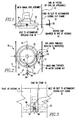
- the lighting apparatus 10 comprises a mounting structure 12.
- the apparatus comprises a gimbal ring assembly 14 for holding a lamp 55.
- the gimbal ring assembly 14 has a first axis 16 and a second axis 18 perpendicular with the first axis 16.
- the gimbal ring assembly 14 is rotatable about the first axis 16 and about the second axis 18.
- the gimbal ring assembly 14 is connected to the mounting structure 12.
- the apparatus comprises a locking mechanism 20 for locking the gimbal ring assembly 14 in a fixed position relative to the first axis 16, to the second axis 18 and the mounting structure 12.
- the gimbal ring assembly 14 comprises an outer ring 22 and an inner ring 24.
- the outer ring 22 is disposed about the inner ring 24.
- the locking mechanism 20 preferably includes a first lock mechanism 26 which locks the inner ring 24 to the outer ring 22 relative to the first axis 16.
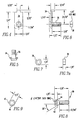
- the first lock mechanism 26 preferably includes a first locking threaded screw or stud 30, as shown in figures 8 and 9, that contacts the outer ring 22 and the inner ring 24.
- the locking mechanism 20 includes a second lock mechanism 28 which locks the outer ring 22 to the mounting structure 12 relative to the second axis 18.
- the mounting structure 12 includes a slot 32 and the second lock mechanism 28 includes a locking clip 34, as shown in figures 4-6, which engages the mounting structure 12 through the hole or slot 32.
- the second lock mechanism 28 includes a second threaded screw or stud 36 that extends through the mounting structure 12 via the locking clip 34 and contacts the outer ring 22.
- the second lock mechanism 28 preferably includes an inner nut 38, as shown in figures 6 and 7, disposed between the inner ring 24 and upper ring.
- the second threaded screw or stud 36 extends through the outer ring 22 and contacts the inner nut 38 which holds the second threaded screw or stud 36 in place so the outer ring 22 cannot rotate about the second axis 18.
- the inner nut 38 has an inner head 46 with holes 44 which are adapted to receive a tool to tighten or loosen the second threaded screw or stud 36 from the nut 38.
- the inner ring 24 has a threaded hole 40 which receives the first locking threaded screw or stud 30 so the first locking threaded screw or stud 30 holds the inner ring 24 and outer ring 22 together and prevents their moving relative to each other about the first axis 16.
- the first locking threaded screw or stud 30 preferably has a locking head 42 with holes 44 which are adapted to receive a tool to tighten or loosen the first locking threaded screw or stud 30.
- the present invention pertains to a lighting apparatus 10.
- the lighting apparatus 10 comprises a yoke 48.
- the apparatus comprises a lamp ring 50 for holding a lamp 55.
- the lamp ring 50 is connected to the mounting structure 12.
- the apparatus comprises a ring locking mechanism 52 for locking the lamp ring 50 in a fixed position relative to the yoke 48.
- the yoke 48 includes a hole or slot 32 and the ring locking mechanism 52 includes a locking clip 34 which engages the yoke 48 through the slot 32.
- the ring locking mechanism 52 includes a second threaded screw or stud 36 that extends through the yoke 48 via the locking clip 34 and contacts the outer ring 22.
- the ring locking mechanism 52 preferably includes an inner nut 38 disposed in the lamp ring 50. The second threaded screw or stud 36 extends through the lamp ring 50 and contacts the inner nut 38 which holds the second threaded screw or stud 36 in place so the lamp ring 50 cannot rotate relative to the yoke 48.
- the present invention pertains to a method for lighting.
- the method comprises the steps of attaching a mounting structure 12 to a ceiling. Then there is the step of orienting an outer ring 22 of a gimbal ring assembly 14 at a first position relative to a second axis 18 of the gimbal ring assembly 14. Next there is the step of locking the outer ring 22 in place relative to the mounting structure 12. Then there is the step of orienting an inner ring 24 having a lamp 55 of the gimbal ring assembly 14 at a second position relative to a first axis 16 of the gimbal ring assembly 14. Next there is the step of locking the inner ring 24 assembly to the outer ring 22 assembly.
- a lighting apparatus 10 is placed in a ceiling. This placement occurs by fixing the mounting structure 12 to the ceiling as is well known in the art.
- the mounting structure 12 is a gimbal ring assembly 14.
- the gimbal ring assembly 14 is comprised of an outer ring 22 and an inner ring 24.
- the gimbal ring assembly can be a standard MR16 gimbal ring assembly available from Modular International, Inc. of Pittsburgh, Pennsylvania.
- the inner ring 24 holds a lamp.
- the inner ring 24 is rotatably connected to the outer ring 22 and the inner ring 24 is able to rotate about a first axis 16 of the gimbal ring assembly 14.
- the outer ring 22 is rotatably attached to the mounting structure 12, as is well known in the art, so that the outer ring 22 can rotate about a second axis 18.
- a first locking threaded screw or stud 30 is screwed through a hole in the outer ring 22 and further threaded into a threaded hole 40 in the inner ring 24.
- the first locking threaded screw or stud 30 is tightened, it screws through the hole in the outer ring 22 and screws in to the threaded hole 40 in the inner ring 24 where it fixes the outer ring 22 with the inner ring 24 so the inner ring 24 cannot move or rotate.
- the first locking threaded screw or stud 30 is tightened to fix the inner ring 24 in place so the lamp remains focused and fixed in place in a desired direction.
- the outer ring 22 is fixed in place after it is rotated to a desired position relative to the second axis 18 by a locking clip 34 first being mounted to the side of the mounting structure 12 through a hole or slot 32 in the mounting structure 12.
- a second threaded screw or stud 36 extends through the locking clip 34 and through a locking clip hole 35 so it extends into the interior of the mounting structure 12.
- the second threaded screw or stud 36 is screwed through a hole in the outer ring 22 that is aligned with the locking clip hole 35 until it threads into an inner nut 38.
- the inner nut 38 is disposed between the inner ring 24 and the outer ring 22.
- the locking nut 38 can have a locking head 42 with holes 44 which receive a tool, such as an Allen wrench, to facilitate tightening or loosening of the second threaded screw or stud 36.
- the inner nut 38 can have an inner head 46 with holes 44 for the same purpose to facilitate tightening or loosening.
- the advantage of the present invention is that it allows the inner ring 24 and outer ring 22 to be fixed in place once the lamp is in the desired position. Whenever the lamp burns out or needs to be changed for whatever reason, whether it be a day, a week, a month or a year later, the lamp can be changed without any concern of disturbing the position the lamp is held in by the gimbal ring assembly. This is because the inner ring 24 and outer ring 22 have become fixed in place through the use of the second threaded screw or stud 36, locking clip 34, inner nut 38, first locking threaded screw or stud 30 and threaded hole 40.
- a yoke 48 which only has a lamp ring 50 can have a locking clip 34 attached to the yoke 48.
- the second threaded screw or stud 36 can then be used with an inner nut 38 to hold the lamp ring 50 in place, for the same reason, as described above.
Landscapes
- Engineering & Computer Science (AREA)
- General Engineering & Computer Science (AREA)
- Non-Portable Lighting Devices Or Systems Thereof (AREA)
Applications Claiming Priority (2)
| Application Number | Priority Date | Filing Date | Title |
|---|---|---|---|
| US161252 | 1998-09-26 | ||
| US09/161,252 US6170965B1 (en) | 1998-09-26 | 1998-09-26 | Method and apparatus for locking a yoke or gimbal ring assembly |
Publications (2)
| Publication Number | Publication Date |
|---|---|
| EP0989360A2 true EP0989360A2 (de) | 2000-03-29 |
| EP0989360A3 EP0989360A3 (de) | 2001-10-10 |
Family
ID=22580448
Family Applications (1)
| Application Number | Title | Priority Date | Filing Date |
|---|---|---|---|
| EP99307525A Withdrawn EP0989360A3 (de) | 1998-09-26 | 1999-09-23 | Beleuchtungsverfahren- und Vorrichtung |
Country Status (2)
| Country | Link |
|---|---|
| US (1) | US6170965B1 (de) |
| EP (1) | EP0989360A3 (de) |
Cited By (9)
| Publication number | Priority date | Publication date | Assignee | Title |
|---|---|---|---|---|
| EP1063467A3 (de) * | 1999-06-25 | 2004-03-24 | Irwin Kotovsky | Beleuchtungs-Verfahren -und Vorrichtung |
| EP2112431A1 (de) * | 2008-04-23 | 2009-10-28 | Martin Professional A/S | Lampeneinstellung bei einem Beleuchtungskörper |
| GB2450986B (en) * | 2007-07-09 | 2010-04-28 | Microlights Ltd | Improvements in and relating to luminaires |
| US7789533B2 (en) | 2008-04-23 | 2010-09-07 | Martin Professional A/S | Lamp support linearly and anguarly adjustable about orthohonal directions |
| NL1037414C2 (en) * | 2009-10-23 | 2011-04-27 | Lucio Internat B V | Two axes gimbals suspension system with single side axes for a recessed lighting fixture. |
| WO2012034858A1 (en) * | 2010-09-16 | 2012-03-22 | Osram Ag | Rotating fixing device and lighting device comprising the device |
| CN101430074B (zh) * | 2008-04-23 | 2013-08-14 | 马田专业公司 | 光源装置和在光源装置中的灯调节方法 |
| EP3232122A1 (de) * | 2016-04-15 | 2017-10-18 | GE Lighting Solutions, LLC | Integrierte kardanische aufhängung für einstellbare leuchte |
| AT515646A3 (de) * | 2014-03-26 | 2018-06-15 | H4X Eu | Halteanordnung für ein Funktionsbauteil einer Beleuchtungsvorrichtung, sowie Beleuchtungsvorrichtung |
Families Citing this family (23)
| Publication number | Priority date | Publication date | Assignee | Title |
|---|---|---|---|---|
| US6446935B1 (en) * | 2000-09-14 | 2002-09-10 | Sharon Piping & Equipment, Inc. | Valve device with elevated mounting pads |
| US6834983B1 (en) * | 2001-05-15 | 2004-12-28 | Michael Lee Guritz | Combination lighting fixture with swivel and mounting post |
| US6997574B2 (en) | 2001-11-02 | 2006-02-14 | Irwin Kotovsky | Method and apparatus for lighting with a one-piece panel having a plurality of holes |
| US7300176B2 (en) | 2003-05-02 | 2007-11-27 | Irwin Kotovsky | Method and apparatus for lighting with reflection |
| US7726483B2 (en) * | 2005-02-23 | 2010-06-01 | The Glad Products Company | Stacked containers |
| US7770857B2 (en) | 2006-06-02 | 2010-08-10 | Francis Ruddy | Universal joint lock |
| US8641241B2 (en) * | 2010-12-14 | 2014-02-04 | Bridgelux, Inc. | Gimbaled LED array module |
| CN206973194U (zh) * | 2017-04-20 | 2018-02-06 | 深圳市大疆灵眸科技有限公司 | 云台结构 |
| US10488000B2 (en) | 2017-06-22 | 2019-11-26 | DMF, Inc. | Thin profile surface mount lighting apparatus |
| WO2018237294A2 (en) | 2017-06-22 | 2018-12-27 | DMF, Inc. | Thin profile surface mount lighting apparatus |
| USD905327S1 (en) | 2018-05-17 | 2020-12-15 | DMF, Inc. | Light fixture |
| WO2019108667A1 (en) | 2017-11-28 | 2019-06-06 | Dmf. Inc. | Adjustable hanger bar assembly |
| CA3103255A1 (en) | 2018-06-11 | 2019-12-19 | DMF, Inc. | A polymer housing for a recessed lighting system and methods for using same |
| USD903605S1 (en) | 2018-06-12 | 2020-12-01 | DMF, Inc. | Plastic deep electrical junction box |
| CA3115146A1 (en) | 2018-10-02 | 2020-04-09 | Ver Lighting Llc | A bar hanger assembly with mating telescoping bars |
| USD864877S1 (en) | 2019-01-29 | 2019-10-29 | DMF, Inc. | Plastic deep electrical junction box with a lighting module mounting yoke |
| USD1012864S1 (en) | 2019-01-29 | 2024-01-30 | DMF, Inc. | Portion of a plastic deep electrical junction box |
| USD901398S1 (en) | 2019-01-29 | 2020-11-10 | DMF, Inc. | Plastic deep electrical junction box |
| USD966877S1 (en) | 2019-03-14 | 2022-10-18 | Ver Lighting Llc | Hanger bar for a hanger bar assembly |
| CA3154491A1 (en) | 2019-09-12 | 2021-03-18 | DMF, Inc. | Miniature lighting module and lighting fixtures using same |
| CA3124976A1 (en) | 2020-07-17 | 2022-01-17 | DMF, Inc. | Polymer housing for a lighting system and methods for using same |
| CA3124987A1 (en) | 2020-07-17 | 2022-01-17 | DMF, Inc. | Bar hanger assembly with crossmembers and housing assemblies using same |
| USD990030S1 (en) | 2020-07-17 | 2023-06-20 | DMF, Inc. | Housing for a lighting system |
Family Cites Families (6)
| Publication number | Priority date | Publication date | Assignee | Title |
|---|---|---|---|---|
| GB233338A (en) * | 1924-04-30 | 1925-11-05 | Ceskomoravska Kolben Akciova S | Improvements in searchlight supporting or suspension devices |
| GB680114A (en) * | 1949-05-17 | 1952-10-01 | Emi Ltd | Improvements in or relating to television apparatus |
| US3086107A (en) * | 1959-06-16 | 1963-04-16 | Color Tran Ind | Adjustable lamp housing |
| US4337506A (en) * | 1978-12-20 | 1982-06-29 | Terada James I | Adjustable lamp |
| CA1124219A (en) * | 1979-06-11 | 1982-05-25 | Isao Yamada | Lighting fixture for use in medical operations and therapeutic treatment |
| DE3807504A1 (de) * | 1988-03-08 | 1989-09-28 | Goller Hilmar Dipl Ing Fh | Beleuchtungseinrichtung |
-
1998
- 1998-09-26 US US09/161,252 patent/US6170965B1/en not_active Expired - Lifetime
-
1999
- 1999-09-23 EP EP99307525A patent/EP0989360A3/de not_active Withdrawn
Non-Patent Citations (1)
| Title |
|---|
| None |
Cited By (10)
| Publication number | Priority date | Publication date | Assignee | Title |
|---|---|---|---|---|
| EP1063467A3 (de) * | 1999-06-25 | 2004-03-24 | Irwin Kotovsky | Beleuchtungs-Verfahren -und Vorrichtung |
| GB2450986B (en) * | 2007-07-09 | 2010-04-28 | Microlights Ltd | Improvements in and relating to luminaires |
| EP2112431A1 (de) * | 2008-04-23 | 2009-10-28 | Martin Professional A/S | Lampeneinstellung bei einem Beleuchtungskörper |
| US7789533B2 (en) | 2008-04-23 | 2010-09-07 | Martin Professional A/S | Lamp support linearly and anguarly adjustable about orthohonal directions |
| CN101430074B (zh) * | 2008-04-23 | 2013-08-14 | 马田专业公司 | 光源装置和在光源装置中的灯调节方法 |
| NL1037414C2 (en) * | 2009-10-23 | 2011-04-27 | Lucio Internat B V | Two axes gimbals suspension system with single side axes for a recessed lighting fixture. |
| WO2012034858A1 (en) * | 2010-09-16 | 2012-03-22 | Osram Ag | Rotating fixing device and lighting device comprising the device |
| AT515646A3 (de) * | 2014-03-26 | 2018-06-15 | H4X Eu | Halteanordnung für ein Funktionsbauteil einer Beleuchtungsvorrichtung, sowie Beleuchtungsvorrichtung |
| AT515646B1 (de) * | 2014-03-26 | 2019-02-15 | H4X Eu | Halteanordnung für ein Funktionsbauteil einer Beleuchtungsvorrichtung, sowie Beleuchtungsvorrichtung |
| EP3232122A1 (de) * | 2016-04-15 | 2017-10-18 | GE Lighting Solutions, LLC | Integrierte kardanische aufhängung für einstellbare leuchte |
Also Published As
| Publication number | Publication date |
|---|---|
| US6170965B1 (en) | 2001-01-09 |
| EP0989360A3 (de) | 2001-10-10 |
Similar Documents
| Publication | Publication Date | Title |
|---|---|---|
| US6170965B1 (en) | Method and apparatus for locking a yoke or gimbal ring assembly | |
| US5291381A (en) | Light fixture mounting assembly | |
| US6511208B1 (en) | Method and apparatus for lighting | |
| US6896436B2 (en) | Adjustable locking mount and methods of use | |
| US5419522A (en) | Universal optical mount | |
| US6016230A (en) | Optical mount with a locking adjustment screw | |
| JP5571666B2 (ja) | 支持装置 | |
| US6966679B2 (en) | Adjustable light fixture mounting assembly | |
| US4946122A (en) | Post clamp | |
| US4687170A (en) | Camera mounting bracket | |
| US3493026A (en) | Locking means for helically movable elements | |
| RU2684671C1 (ru) | Крепежная система | |
| US6550731B1 (en) | Device for mounting sign of direction to post | |
| US7455273B2 (en) | Projector holder | |
| US3605508A (en) | Precision threaded adjustment | |
| JP2002517880A (ja) | 照明装置 | |
| US8002227B2 (en) | Pivot and tilt apparatus | |
| JP2002374108A (ja) | アンテナ取付金具 | |
| US20080315479A1 (en) | Positioning System for a Component, Adjustment Tool and Adjustment Method | |
| CA2543278C (en) | Universal mounting for a vehicle rear view mirror | |
| KR100514210B1 (ko) | 밀링공구의 로케터 조정장치 | |
| US20240247678A1 (en) | Stop turn fitting | |
| SU1454427A1 (ru) | Устройство дл установки костных трансплантатов при компрессионной краниопластике | |
| JP3082295U (ja) | 綾目ねじナットを使用した調整個所の耐震固定ねじ装置 | |
| JPH10125126A (ja) | 照明器具 |
Legal Events
| Date | Code | Title | Description |
|---|---|---|---|
| PUAI | Public reference made under article 153(3) epc to a published international application that has entered the european phase |
Free format text: ORIGINAL CODE: 0009012 |
|
| AK | Designated contracting states |
Kind code of ref document: A2 Designated state(s): AT BE CH CY DE DK ES FI FR GB GR IE IT LI LU MC NL PT SE |
|
| AX | Request for extension of the european patent |
Free format text: AL;LT;LV;MK;RO;SI |
|
| PUAL | Search report despatched |
Free format text: ORIGINAL CODE: 0009013 |
|
| AK | Designated contracting states |
Kind code of ref document: A3 Designated state(s): AT BE CH CY DE DK ES FI FR GB GR IE IT LI LU MC NL PT SE |
|
| AX | Request for extension of the european patent |
Free format text: AL;LT;LV;MK;RO;SI |
|
| 17P | Request for examination filed |
Effective date: 20020403 |
|
| AKX | Designation fees paid |
Free format text: AT BE CH CY DE DK ES FI FR GB GR IE IT LI LU MC NL PT SE |
|
| STAA | Information on the status of an ep patent application or granted ep patent |
Free format text: STATUS: THE APPLICATION IS DEEMED TO BE WITHDRAWN |
|
| 18D | Application deemed to be withdrawn |
Effective date: 20060225 |