EP0989310A2 - Schnellverstellmutter - Google Patents
Schnellverstellmutter Download PDFInfo
- Publication number
- EP0989310A2 EP0989310A2 EP99115630A EP99115630A EP0989310A2 EP 0989310 A2 EP0989310 A2 EP 0989310A2 EP 99115630 A EP99115630 A EP 99115630A EP 99115630 A EP99115630 A EP 99115630A EP 0989310 A2 EP0989310 A2 EP 0989310A2
- Authority
- EP
- European Patent Office
- Prior art keywords
- nut
- quick
- adjusting nut
- threaded rod
- thread
- Prior art date
- Legal status (The legal status is an assumption and is not a legal conclusion. Google has not performed a legal analysis and makes no representation as to the accuracy of the status listed.)
- Withdrawn
Links
- 230000000295 complement effect Effects 0.000 claims description 2
- 230000035515 penetration Effects 0.000 claims 2
- 239000000725 suspension Substances 0.000 abstract description 18
- 239000002184 metal Substances 0.000 description 3
- 230000000149 penetrating effect Effects 0.000 description 3
- 238000002347 injection Methods 0.000 description 1
- 239000007924 injection Substances 0.000 description 1
- 230000002093 peripheral effect Effects 0.000 description 1
Images

Classifications
-
- F—MECHANICAL ENGINEERING; LIGHTING; HEATING; WEAPONS; BLASTING
- F16—ENGINEERING ELEMENTS AND UNITS; GENERAL MEASURES FOR PRODUCING AND MAINTAINING EFFECTIVE FUNCTIONING OF MACHINES OR INSTALLATIONS; THERMAL INSULATION IN GENERAL
- F16B—DEVICES FOR FASTENING OR SECURING CONSTRUCTIONAL ELEMENTS OR MACHINE PARTS TOGETHER, e.g. NAILS, BOLTS, CIRCLIPS, CLAMPS, CLIPS OR WEDGES; JOINTS OR JOINTING
- F16B37/00—Nuts or like thread-engaging members
- F16B37/08—Quickly-detachable or mountable nuts, e.g. consisting of two or more parts; Nuts movable along the bolt after tilting the nut
- F16B37/0871—Quickly-detachable or mountable nuts, e.g. consisting of two or more parts; Nuts movable along the bolt after tilting the nut engaging the bolt laterally, i.e. without the need to engage the end of the bolt
- F16B37/0885—Quickly-detachable or mountable nuts, e.g. consisting of two or more parts; Nuts movable along the bolt after tilting the nut engaging the bolt laterally, i.e. without the need to engage the end of the bolt in two halves hingedly connected
Definitions
- the invention relates to a quick adjusting nut, in particular for attaching a suspended ceiling provided on a threaded rod attached to a ceiling is.
- suspension wires are known, on which an in Adjustable suspension clip is attached in the longitudinal direction of the suspension wire.
- the hanging clip is a bracket made of spring sheet metal, which has two holes with which the suspension clips is pushed onto the suspension wire. By squeezing two free ends of the suspension clip can be moved freely on the suspension wire. If the two ends of the suspension clip are released, the suspension clip will tilt due to its spring force on the suspension wire and is thereby fixed.
- the Suspended wire is attached to the building ceiling, the suspended one is attached to the suspension clip Ceiling attached. The load capacity of such a suspension clip is limited.
- a nut can be screwed onto a threaded rod be attached to the ceiling of the building in place of the suspension wire.
- the suspended ceiling is attached to the mother. This has the disadvantage that the mother for Adjustment of the height of the suspended ceiling often over a large length of the threaded rod must be screwed, which is time consuming.
- the invention has for its object to provide a quick adjusting nut adjustable and screwed on a threaded rod in the longitudinal direction without screwing a desired point can be brought into engagement with the threaded rod.
- the quick-adjusting nut according to the invention has a nut body which with a Longitudinal slot through the entire length of a nut thread is provided.
- the slot does not need to run in the longitudinal direction, for example also run at an angle to the longitudinal direction or helically.
- the nut body expandable so that the quick adjustment nut is disengaged from one to the nut thread complementary bolt thread can be brought.
- the nut body of the invention Quick adjustment nut can therefore be widened and expanded Slide onto a threaded rod without turning and in the longitudinal direction of the threaded rod to a desired position on the threaded rod.
- the quick adjustment nut is narrowed again and the nut thread thereby engaged with a bolt thread of the threaded rod. After that the quick adjustment nut can be screwed onto the threaded rod for fine adjustment and the suspended ceiling can be attached to the nut.
- the quick adjusting nut according to the invention has the advantage that it is quick and without Screw movement can be brought to a desired location on a threaded rod can. Then the quick adjustment nut according to the invention can be used like a conventional one Adjust the nut in the longitudinal direction of the threaded rod using screws. Another advantage of the quick adjustment nut according to the invention is its high load capacity, which corresponds to that of a conventional mother.
- the nut body is the quick-adjusting nut formed elastic and thereby expandable, so that the quick adjusting nut except Engagement can be brought from the threaded rod.
- the nut body is divided into two or more parts.
- the parts of the nut body are pivotally connected to each other via a hinge, so that the quick adjustment nut by swinging the parts of her Nut body can be brought out of engagement by the threaded rod.
- the hinge can be used as Be articulated, but it can also be a spring clip or the like.
- the quick adjustment nut has a releasable securing device which secures the nut body against expansion and thereby holds in engagement on the threaded rod.
- the safety device secures the quick adjustment nut against unintentional loosening from the threaded rod. Another advantage of The safety device is that the one in engagement on the threaded rod Quick adjustment nut not as a result of a load, for example, from one of the Expand the quick-adjusting nut on the attached load and thereby disengage from the threaded rod can reach.
- the load capacity of the quick adjustment nut is determined by the safety device elevated.
- the securing device is in the form of a securing ring trained who placed the nut body encompassing the quick adjustment nut becomes.
- the locking ring prevents the nut body from expanding and thus holds the quick adjustment nut engages on the threaded rod.
- the securing device has two Tabs on both sides of the longitudinal thread penetrating the nut thread Slot are attached to the nut body.
- the tabs can be made in one piece with the Be the nut body. The tabs protrude outwards from the nut body.
- the tabs can also be spaced apart have, the distance of the tabs is limited by the connector, so that the nut body cannot be expanded.
- the detachable connector can, for example be a hook that overlaps or passes through the two tabs and thereby to each other holds. Such a hook can be an end of a wire on which the suspended one Ceiling is attached. In this way, by attaching a load to the invention Quick adjustment nut the locking device in a locking position fixed and the quick adjustment nut held in engagement with the threaded rod.
- one of the two tabs has a reach-through element that passes through an opening in the other tab.
- the quick adjustment nut according to the invention including its securing device made in one piece.
- it can be made as an injection molded part Be made of plastic or as a metal part.
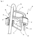
- the quick adjustment nut according to the invention shown in FIG. 1, designated overall by 10 has two half-nuts 12, one also designated 12 Form the nut body.
- the nut body 12 is separated by two opposing slots 14 arranged in an axial plane are divided into the two half-nuts 12.
- Figure 1 shows the quick adjusting nut 10 in an open state in which the nut body 12 expanded, d. H. the half nuts 12 are apart. in the When open, the slots 14 are wide.
- Each of the two half-nuts 12 extends circumferentially around a little less than a semicircle.
- Each of the two half-nuts 12 has one half of a nut thread 16
- the two half-nuts 12 are pivotally connected to one another via a hinge 18:
- Crosspieces 20 are arranged on either side of one of the two slots 14 on the half nuts 12 and project approximately radially from the half nuts 12. With distance the webs 20 extend from the half-nuts 12 after they have been bent by 90 ° axially parallel to the nut body 12 and after a further angling 24 to likewise 90 ° radially inward again, where the two webs 20 are in the region of a circumference unite the nut body 12.
- the association is designated with reference number 25.
- the webs 20 have a U-shape in a side view. Due to their elastic Deformability allows the webs 20 forming the hinge 18 to separate and Swiveling the half nuts together 12.
- the webs 20 go in one piece into a locking ring 26 about who is on one end of the two half-nuts 12 and the Inner diameter is larger than an outer diameter of the nut thread 16.
- the Circlip 26 is provided for engagement in a groove 30 which is close to that of the circlip 26 facing end of the half nuts 12 in an outer peripheral surface the half nuts 12 is attached.
- the groove 30 sits over both half nuts 12 away.
- a chamfer 32 makes it easier to snap the locking ring 26 into the groove 30 of the two half nuts 12 when the half nuts 12 are pivoted together.
- the two rings 20 forming the hinge 18 have the locking ring 26 a widening 34 in which a hole 36 is made as a hanging device.
- the function of the quick adjustment nut 10 according to the invention shown in FIG. 1 is the following:
- the quick adjustment nut 10 is for fastening a suspended ceiling provided on a building ceiling (not shown).
- the quick adjusting nut 10 on a for clarity, because of the not shown threaded rod, which is attached to the Ceiling is attached.
- the quick adjustment nut can be opened when it is open 10 without turning or screwing in the axial direction on the threaded rod move.
- the two are the Nut body 12 forming half-nuts 12 compressed so that the nut thread 12 comes into engagement with a bolt thread of the threaded rod.
- the locking ring 26 is pressed onto the compressed half nuts 12, whereby it slides over the chamfer 32 of the half-nuts 12 and into the groove 30 of the Half nuts 12 clicks into place.
- the two half-nuts 12 are in their compressed, fixed position, not shown, in which it engages with its nut thread 16 stand the bolt thread of the threaded rod, not shown.
- the in the groove 30 of the Half-nuts 12 snap ring 26 holds the half-nuts 12 in engagement with the bolt thread.
- the quick adjustment nut can 10 screw back and forth on the threaded rod like a conventional nut, whereby a fine adjustment is possible.
- FIG. 2 shows a second embodiment of a quick adjusting nut according to the invention 10.
- the same reference numbers as in FIG. 1 are used for the same parts below used.
- the quick adjustment nut 10 shown in FIG. 2 has two half nuts 12 on, which form a nut body 12.
- the two half-nuts 12 are by two each other opposite longitudinal slots 14 arranged opposite each other Cut.
- the half nuts 12 are provided with a nut thread 16.
- the hinge 18 has two hinge flanges 42, which are located on both sides of the other longitudinal slot 14 approximately radial to the nut body 12 and parallel to one another with one of the Width of the longitudinal slot 14 corresponding distance from each other to the outside Stick out half-nuts 12.
- the hinge flanges 42 merge at their outer ends a 180 ° bend 44 in one piece.
- the hinge flanges 42 are from passes through a hole, which is congruently attached in both hinge flanges 42 and which forms a suspension device 36.
- the function of the quick adjustment nut 10 shown in FIG. 2 is as follows:
- the Schnellverstellmutter 10 can for example by means of a, not shown, between widen the two expansion flanges 40 of the screwdriver attached, d. H. their two half-nuts 12 are pivoted apart. In the expanded position can the Schnellverstellmutter 10 on a not shown, on a ceiling Move the attached threaded rod in the axial direction. When spreading the the hinge flanges 42 forming the hinge 18 including their 180 ° bend 44 elastically deformed. The expansion is made at a desired point on the threaded rod released and the hinge 18 presses the half-nuts 12 together.
- the nut thread 16 of the half nuts 12 comes in with the bolt thread of the threaded rod Engagement and is held in engagement by the elasticity of the hinge 18.
- the quick adjustment nut 10 can be shown in the unexpanded, in the drawing Move the position like a conventional nut on the threaded rod by screwing.
- the quick adjustment nut 10 is in the desired position on the Threaded rod, a wire 38 bent into a hook can be inserted into the hanging device 36 forming hole in the hinge flanges 42 are hung.
- the one Hook bent wire 38 holds the hinge flanges 22 together so that the hinge flanges 42 cannot be separated.
- the held together Hinge flanges 42 hold the half nuts 12 together so that they are not except Engagement can be brought from the bolt thread of the threaded rod.
- the hinge 18 thus forms a securing device with the hole 36 forming the suspension device, the engagement of the quick adjustment nut 10 by hanging the wire 38 in the bolt thread of the threaded rod. Also one to the quick adjustment nut 10 attached load, the secured quick adjustment nut 10 cannot disengage bring from the bolt thread of the threaded rod.
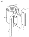
- FIG 3 shows a third embodiment of a quick adjusting nut according to the invention 10.
- the quick adjustment nut 10 shown in Figure 3 has a nut body 12 with a continuous longitudinal slot 14.
- the nut body 12 points in the circumferential direction a wrap angle of over 270 ° and less than 360 °.
- the Nut body 12 is provided with a nut thread 16.
- Flanges 46, 48 are integral with the nut body 12.
- One of the two flanges 46 has an opening in the form of a rectangular hole 50 on.
- the other flange 48 is in its central region to a U-shaped flat bracket 52 formed, which protrudes in the direction of one flange 46 from the other flange 48 and penetrates the rectangular hole 50.
- the function of the quick adjustment nut 10 shown in FIG. 3 is as follows: For example by pressure on the U-shaped which penetrates a flange 46 Flat bracket 52 or by attaching a screwdriver, not shown, between the two flanges 46, 48, the nut body 12 can be elastically expanded. In the expanded position, not shown, the quick adjusting nut 10 without turning or screwing axially on a ceiling, Move the threaded rod, not shown. At a desired point the Expansion widened, whereby the nut body 12 due to its elasticity narrowed its original starting state shown in the drawing.
- the quick adjustment nut can be used like a conventional one Screw the nut onto the threaded rod.
- the one penetrating hole 50 U-shaped flat bracket 52 forms a safety and hanging device.
- Hooking a wire 38 bent into a hook into the one flange 46 penetrating U-shaped flat bracket 52 prevents the flanges 46, 48th can separate from each other. This in turn prevents the nut body 12 can expand, d. H.
- the engagement of the quick adjustment nut 10 in the bolt thread of the threaded rod is through the wire suspended in the U-shaped flat bracket 52 38 ensured.
- a suspended ceiling not shown, is attached to the wire 38 or attachable.
- the quick adjustment nuts shown in Figures 1 to 3 are in one piece, for example made of plastic or metal.
Landscapes
- Engineering & Computer Science (AREA)
- General Engineering & Computer Science (AREA)
- Mechanical Engineering (AREA)
- Mutual Connection Of Rods And Tubes (AREA)
- Turbine Rotor Nozzle Sealing (AREA)
- Residential Or Office Buildings (AREA)
- Supports For Pipes And Cables (AREA)
Abstract
Description
Claims (9)
- Schnellverstellmutter, dadurch gekennzeichnet, daß die Schnellverstellmutter (10) einen ein Mutterngewinde (16) aufweisenden Mutternkörper (12) mit einem in Längsrichtung über die gesamte Länge des Mutterngewindes (16) durchgehenden Schlitz (14) aufweist, und daß der Mutternkörper (12) aufweitbar ausgebildet ist, so daß die Schnellverstellmutter (10) außer Eingriff von einem zum Mutterngewinde (16) komplementären Bolzengewinde bringbar ist.
- Schnellverstellmutter nach Anspruch 1, dadurch gekennzeichnet, daß der Mutternkörper (12) elastisch aufweitbar ist.
- Schnellverstellmutter nach Anspruch 1, dadurch gekennzeichnet, daß der Mutternkörper (12) geteilt ist und ein Scharnier (18) aufweist, das Teile des Mutternkörpers (12) schwenkbar miteinander verbindet.
- Schnellverstellmutter nach Anspruch 1, dadurch gekennzeichnet, daß die Schnellverstellmutter (10) eine lösbare Sicherungseinrichtung (26; 42; 52) aufweist, die den Mutternkörper (12) gegen Aufweitung sichert.
- Schnellverstellmutter nach Anspruch 4, dadurch gekennzeichnet, daß die Sicherungseinrichtung einen Sicherungsring (26) aufweist, der den Mutternkörper (12) umgreift und gegen Aufweitung sichert.
- Schnellverstellmutter nach Anspruch 4, dadurch gekennzeichnet, daß die Sicherungseinrichtung zwei Flansche (42; 46, 48) aufweist, die beiderseits des Schlitzes (14) nach außen vom Mutternkörper (12) abstehen, und daß die Sicherungseinrichtung einen lösbaren Verbinder (38, 52) aufweist, der die beiden Flansche (42; 46, 48) aneinander hält.
- Schnellverstellmutter nach Anspruch 6, dadurch gekennzeichnet, daß einer der beiden Flansche (46) eine Öffnung (50) aufweist, die von einem Durchgreifelement (52) des anderen Flansches (48) durchgriffen wird, und daß das Durchgreifelement (52) mittels eines Sicherungselements (38) an dem durchgriffenen Flansch (46) sicherbar ist.
- Schnellverstellmutter nach Anspruch 4, dadurch gekennzeichnet, daß die Sicherungseinrichtung (26; 42; 52) eine Einhängeeinrichtung (36; 52) aufweist, die durch Einhängen eines Gegenstandes (38) die Sicherungseinrichtung (26; 52) in einer Sicherungsstellung hält.
- Schnellverstellmutter nach Anspruch 1, dadurch gekennzeichnet, daß die Schnellverstellmutter (10) einstückig ist.
Applications Claiming Priority (2)
| Application Number | Priority Date | Filing Date | Title |
|---|---|---|---|
| DE19843218A DE19843218A1 (de) | 1998-09-22 | 1998-09-22 | Schnellverstellmutter |
| DE19843218 | 1998-09-22 |
Publications (2)
| Publication Number | Publication Date |
|---|---|
| EP0989310A2 true EP0989310A2 (de) | 2000-03-29 |
| EP0989310A3 EP0989310A3 (de) | 2000-11-22 |
Family
ID=7881690
Family Applications (1)
| Application Number | Title | Priority Date | Filing Date |
|---|---|---|---|
| EP99115630A Withdrawn EP0989310A3 (de) | 1998-09-22 | 1999-08-07 | Schnellverstellmutter |
Country Status (4)
| Country | Link |
|---|---|
| EP (1) | EP0989310A3 (de) |
| DE (1) | DE19843218A1 (de) |
| HU (1) | HUP9902854A2 (de) |
| PL (1) | PL335539A1 (de) |
Cited By (2)
| Publication number | Priority date | Publication date | Assignee | Title |
|---|---|---|---|---|
| EP1445499A4 (de) * | 2001-11-15 | 2005-10-05 | Mirai Kogyo Kabushiki Kaisha | Montagekörper zur befestigung an einem schrauben- und mutternkörper |
| US12163549B2 (en) | 2019-12-23 | 2024-12-10 | Continental Automotive Systems, Inc. | Hinged retainer assembly |
Families Citing this family (2)
| Publication number | Priority date | Publication date | Assignee | Title |
|---|---|---|---|---|
| FR2960606B1 (fr) * | 2010-05-28 | 2013-03-29 | Lisi Automotive Rapid | Agrafe de maintien d'objets tels que des canalisations sur une structure de support, par l'intermediaire d'un goujon filete |
| DE102016222197A1 (de) | 2016-11-11 | 2018-05-17 | Ejot Gmbh & Co. Kg | Einstellvorrichtung |
Family Cites Families (6)
| Publication number | Priority date | Publication date | Assignee | Title |
|---|---|---|---|---|
| US1375781A (en) * | 1920-06-08 | 1921-04-26 | Long George R De | Nut |
| DE7146313U (de) * | 1971-12-09 | 1972-03-16 | Matis E | Schraubenverbindung |
| GB2196404A (en) * | 1986-09-20 | 1988-04-27 | Darenth Valley Golf Course Lim | Fastening element |
| GB2239481B (en) * | 1989-12-28 | 1993-09-15 | Inaba Denki Sangyo Kk | Nut,and a device using the nut for clamping and supporting elongate objects |
| DE29713940U1 (de) * | 1997-08-05 | 1998-09-17 | A. Raymond & Cie, Grenoble | Lösbare Federmutter für Gewindebolzen |
| DE19903972C2 (de) * | 1999-01-23 | 2002-03-14 | Dirk Marky | Federmutter zur Schnellbefestigung |
-
1998
- 1998-09-22 DE DE19843218A patent/DE19843218A1/de not_active Withdrawn
-
1999
- 1999-08-07 EP EP99115630A patent/EP0989310A3/de not_active Withdrawn
- 1999-08-25 HU HU9902854A patent/HUP9902854A2/hu unknown
- 1999-09-22 PL PL99335539A patent/PL335539A1/xx unknown
Non-Patent Citations (1)
| Title |
|---|
| None |
Cited By (2)
| Publication number | Priority date | Publication date | Assignee | Title |
|---|---|---|---|---|
| EP1445499A4 (de) * | 2001-11-15 | 2005-10-05 | Mirai Kogyo Kabushiki Kaisha | Montagekörper zur befestigung an einem schrauben- und mutternkörper |
| US12163549B2 (en) | 2019-12-23 | 2024-12-10 | Continental Automotive Systems, Inc. | Hinged retainer assembly |
Also Published As
| Publication number | Publication date |
|---|---|
| HU9902854D0 (en) | 1999-10-28 |
| PL335539A1 (en) | 2000-03-27 |
| HUP9902854A2 (hu) | 2000-05-28 |
| DE19843218A1 (de) | 2000-03-23 |
| EP0989310A3 (de) | 2000-11-22 |
Similar Documents
| Publication | Publication Date | Title |
|---|---|---|
| DE3633486C1 (de) | Schlauchklemme | |
| DE602004001734T2 (de) | Ein Befestigungselement zur Verbindung von an einem Trägerteil | |
| WO2003048591A1 (de) | Verbindungsmutter zum anschrauben von konstruktionselementen an einem plattenartigen bauteil | |
| DE69212963T2 (de) | Selbstspannende Klemme | |
| DE102017002322B4 (de) | Mehrfachbefestigungsmittel mit zumindest einem Formschluss-Verbindungsabschnitt sowie Befestigungssystem mit einem solchen Mehrfachbefestigungsmittel | |
| DE2650480C3 (de) | Aufhängevorrichtung | |
| DE2144914A1 (de) | Aufhängevorrichtung | |
| DE102009045484A1 (de) | Leitungsabhängeeinrichtung | |
| AT391747B (de) | Rohrschelle | |
| EP0989310A2 (de) | Schnellverstellmutter | |
| DE19722778C1 (de) | Verankerungseinheit | |
| DE2441297A1 (de) | Befestigungssystem fuer rohre o.dgl. | |
| CH640622A5 (en) | Attachment device for pipes or similar objects | |
| DE2928917C2 (de) | Säulenartiges Stützrohr für Kleinbauten, insbesondere für Skelettrahmenkonstruktionen | |
| DE19625665A1 (de) | Elektrisches Installationsgerät | |
| EP3599338A1 (de) | Aufhängungsvorrichtung zur befestigung von storen | |
| DE19734601A1 (de) | Lochscheibe | |
| DE102018107083A1 (de) | Befestigungseinrichtung und Verfahren zur Befestigung eines Anbauteils an einem Tragteil, Bauteilsystem und Kraftfahrzeug | |
| EP1243203B1 (de) | Schienenmontagesystem | |
| EP0508300A2 (de) | Aufhängevorrichtung für eine Luftkabelgarnitur | |
| EP0667463B1 (de) | Halteelement aus Kunststoff, insbesondere für Rohrleitungen | |
| DE19842171B4 (de) | Rohrschelle | |
| EP0655300A1 (de) | Vorrichtung zur Befestigung eines Rohres in einem Hülsenteil | |
| EP1024303B1 (de) | Befestigungselement für Gewindebolzen | |
| DE102024105003B3 (de) | Montageklammer, Montagesystem und Verfahren zum Anbringen einer Montageklammer an einer Montageschiene |
Legal Events
| Date | Code | Title | Description |
|---|---|---|---|
| PUAI | Public reference made under article 153(3) epc to a published international application that has entered the european phase |
Free format text: ORIGINAL CODE: 0009012 |
|
| AK | Designated contracting states |
Kind code of ref document: A2 Designated state(s): AT BE CH CY DE DK ES FI FR GB GR IE IT LI LU MC NL PT SE |
|
| AX | Request for extension of the european patent |
Free format text: AL;LT;LV;MK;RO;SI |
|
| PUAL | Search report despatched |
Free format text: ORIGINAL CODE: 0009013 |
|
| AK | Designated contracting states |
Kind code of ref document: A3 Designated state(s): AT BE CH CY DE DK ES FI FR GB GR IE IT LI LU MC NL PT SE |
|
| AX | Request for extension of the european patent |
Free format text: AL;LT;LV;MK;RO;SI |
|
| 17P | Request for examination filed |
Effective date: 20010323 |
|
| AKX | Designation fees paid |
Free format text: AT BE CH CY DE DK ES FI FR GB GR IE IT LI LU MC NL PT SE |
|
| 17Q | First examination report despatched |
Effective date: 20030710 |
|
| STAA | Information on the status of an ep patent application or granted ep patent |
Free format text: STATUS: THE APPLICATION IS DEEMED TO BE WITHDRAWN |
|
| 18D | Application deemed to be withdrawn |
Effective date: 20031121 |