EP0988913A2 - Schneideeinrichtung mit distanziert aufgespanntem Kreisschermesser - Google Patents
Schneideeinrichtung mit distanziert aufgespanntem Kreisschermesser Download PDFInfo
- Publication number
- EP0988913A2 EP0988913A2 EP99890264A EP99890264A EP0988913A2 EP 0988913 A2 EP0988913 A2 EP 0988913A2 EP 99890264 A EP99890264 A EP 99890264A EP 99890264 A EP99890264 A EP 99890264A EP 0988913 A2 EP0988913 A2 EP 0988913A2
- Authority
- EP
- European Patent Office
- Prior art keywords
- ring part
- cutting device
- outer ring
- inner ring
- rings
- Prior art date
- Legal status (The legal status is an assumption and is not a legal conclusion. Google has not performed a legal analysis and makes no representation as to the accuracy of the status listed.)
- Granted
Links
Images
Classifications
-
- B—PERFORMING OPERATIONS; TRANSPORTING
- B23—MACHINE TOOLS; METAL-WORKING NOT OTHERWISE PROVIDED FOR
- B23D—PLANING; SLOTTING; SHEARING; BROACHING; SAWING; FILING; SCRAPING; LIKE OPERATIONS FOR WORKING METAL BY REMOVING MATERIAL, NOT OTHERWISE PROVIDED FOR
- B23D19/00—Shearing machines or shearing devices cutting by rotary discs
- B23D19/04—Shearing machines or shearing devices cutting by rotary discs having rotary shearing discs arranged in co-operating pairs
- B23D19/06—Shearing machines or shearing devices cutting by rotary discs having rotary shearing discs arranged in co-operating pairs with several spaced pairs of shearing discs working simultaneously, e.g. for trimming or making strips
-
- B—PERFORMING OPERATIONS; TRANSPORTING
- B23—MACHINE TOOLS; METAL-WORKING NOT OTHERWISE PROVIDED FOR
- B23D—PLANING; SLOTTING; SHEARING; BROACHING; SAWING; FILING; SCRAPING; LIKE OPERATIONS FOR WORKING METAL BY REMOVING MATERIAL, NOT OTHERWISE PROVIDED FOR
- B23D35/00—Tools for shearing machines or shearing devices; Holders or chucks for shearing tools
- B23D35/005—Adjusting the position of the cutting members
- B23D35/007—Adjusting the position of the cutting members for circular cutting members
Definitions
- the invention relates to a cutting device for creating at least one uninterrupted cutting of flat material, at least on two shafts of circular shear knives, which work together to create Intermediate rings are stretched apart.
- the face-finely ground or lapped for example to 1 to 2 ⁇ m Roughing depth worked circular shear knives, which worked precisely with the same Spacers or spacers are spaced on top of each other opposite waves such that the rings by means of different widths required product width and in the cutting area the desired or intended gap between the overlapping side surfaces of the knives can be achieved.
- Circular shear knives often have an outer diameter of up to 500 mm and larger. This usually indicates a high accuracy of the clamping in the axial direction System: Circular shear knife intermediate ring clamping part cooperating support surfaces on, which extend radially to close to the cutting edges, so that the The outer diameter of the spacer rings may only be slightly smaller than that is the circular shear knife and this results in a large spacer ring volume.
- Thick spacer rings or wide spacer rings with a larger diameter that Steel are made have a high mass or due to the large volume often have a considerable weight.
- the intermediate rings When loading a cutting device the intermediate rings must be pushed onto the shafts, which According to the weight, there are often problems with manipulation and in particular the danger damage and wear to parts of the cutting device brings itself.
- Spacer rings with a comparatively low weight which have a plastic ring body which is coaxial in the longitudinal axial direction A large number of hard spacer bars, which support the circular cutter, is interspersed.
- Such an embodiment of an intermediate ring is indeed one Ensure the desired clamping accuracy of the knives, however, can lead to end-face knife wear and also has the disadvantage of a high Manufacturing effort and the problem of mutual support thinner Rings.
- lighter metals such as titanium is for one Spacer ring production, but it has become economical Reasons not enforced.
- the invention has for its object the disadvantages of the known Eliminate intermediate rings and a cutting device of the aforementioned To create style with spacer rings that are light in weight, high in weight Ensure the clamping accuracy of the circular knives on the shafts is low Have wear and the like when loading the Effect cutting device and low manufacturing costs or high Have economy.
- the intermediate rings consist of at least two, essentially concentric Arranged parts consist, with the outer ring part made of a material high compressive strength and the ax nearer or inner ring part from such with lower specific weight is formed.
- the advantages of being trained Intermediate rings between the knife disks can essentially be seen in that on the one hand a clamping of the parts on the shafts by means of a concentric ring-shaped surface with a large axial distance, which makes stable and precise ax normal face positioning and thus one the same cutting edge holder are given. Even when cutting from to Example of tough-hard sheet metal, possibly occurring forces in the axial direction this does not lead to widening of the cutting gap of the pair of knives.
- the concentricity of the circular surface is indicated by a slight Inner part that only the radial mounting of the ring on the shaft to the task has accomplished, resulting in a significant reduction in the Spacer ring weight leads.
- the outer ring part of the intermediate rings is made of metal, preferably steel, with a 0.02 strength limit of greater than 100 N / mm 2 .
- a particularly preferred form of the invention is given if the end faces of the outer ring part of the intermediate rings, which bear against a side surface of a circular shear knife, against a similar surface of a clamping part or against another ring part, have a size whose value A [in mm 2 ] 1.12 to 1.78 times the highest axial clamping force F [in N] broken by the lowest 0.02 limit of the strength of the material [in N / mm 2 ] from the outer ring part, circular shear knife and clamping part.
- the smallest spacer ring weights can be achieved with high clamping accuracy and problem-free material pressure stress even in long-term use.
- the intermediate ring as an ejector is formed for the sheet material after the cut, being on the outside of the outer ring part is a part that is elastic in the radial direction, for example a Rubber or spring washer or the like is arranged, a high Operational reliability of the cutting device and an improved flatness of the Cuttings achieved.
- the axially closer or inner ring part of the intermediate ring preferably has a weight of less than 45 kN / m 3 , which brings about an efficient reduction in the spacer ring weight.
- An improvement of deferment when loading the waves of the Cutting device, but also security against twisting can be achieved be when the inner ring part of the intermediate ring at least one Has recess, it being particularly advantageous if the radial (n) in Recess (s) running in the axial direction in the inner ring part of the intermediate ring extends to the outer ring part thereof.
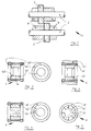
- Fig. 1 is a part of a cutting device 1, namely two circular shear blades 3, which work together to create cuts, generally shown.
- a cutting device namely two circular shear blades 3, which work together to create cuts, generally shown.
- On opposite shafts 2 are each circular knives 3 positioned such that an outer area of the end faces of the knives 3 overlap one another.
- a Positioning in the axial direction of the interacting circular cutter 3 on the Shafts 2 take place via intermediate rings or spacer rings 4.
- Fig. 2 shows an intermediate or spacer ring 4 according to the invention in section and in view, which according to the invention essentially consists of an outer ring part 41 and an inner ring portion 42 is formed. On the outer ring part 41 are end faces 411, which transmit the clamping forces, with high parallelism and Surface quality manufactured.
- FIG. 3 an intermediate or spacer ring 4 is shown, the one outside Ejector 43 has.
- the ejector 43 is made of elastic in the illustration Material, for example rubber, and is glued to the outer ring 41 connected.
- Fig. 4 illustrates a spacer ring 4, the one in the inner ring part 42 Has recess 45, which has a space for a wedge on a shaft 2 can form.
- FIG. 5 shows an intermediate ring 4, in which an inner ring 42 is made Segments, which segments are connected with an outer ring. Recesses 45 are formed in each case between the segments 42.
Landscapes
- Engineering & Computer Science (AREA)
- Mechanical Engineering (AREA)
- Nonmetal Cutting Devices (AREA)
- Control And Other Processes For Unpacking Of Materials (AREA)
- Threshing Machine Elements (AREA)
- Crushing And Pulverization Processes (AREA)
- Finish Polishing, Edge Sharpening, And Grinding By Specific Grinding Devices (AREA)
- Absorbent Articles And Supports Therefor (AREA)
- Mechanical Treatment Of Semiconductor (AREA)
Abstract
Description
Es zeigt jeweils in schematischer Darstellung:
Claims (10)
- Schneideinrichtung (1) zur Erstellung mindestens eines ununterbrochenen Schnittes von flächigem Material, bei welcher auf mindestens zwei Wellen (2) Kreisschermesser (3), die schnitterzeugend zusammenwirken, durch Zwischenringe (4) distanziert, aufgespannt sind, dadurch gekennzeichnet, daß die Zwischenringe (4) aus mindestens zwei, im wesentlichen konzentrisch angeordneten Teilen bestehen, wobei der äußere Ringteil (41) aus einem Werkstoff mit hoher Druckfestigkeit und der axnähere bzw. innere Ringteil (42) aus einem solchen mit geringem spezifischen Gewicht gebildet ist.
- Schneideinrichtung nach Anspruch 1, dadurch gekennzeichnet, daß der äußere Ringteil (41) der Zwischenringe (4) aus Metall, vorzugsweise aus Stahl mit einer 0,02 Grenze der Festigkeit von größer als 100 N/mm2 gebildet ist.
- Schneideinrichtung nach Anspruch 1 oder 2, dadurch gekennzeichnet, daß die Stirnflächen (411) des äußeren Ringteiles (41) der Zwischenringe (4), die an einer Seitenfläche eines Kreisschermessers (3), an einer dergleichen Fläche eines Spannteiles oder an einem weiteren Ringteil (4 ) anliegen, eine Größe aufweisen, deren Wert A [in mm2] 1,12 bis 1,78mal der höchsten axialen Aufspannkraft F [in N] gebrochen durch die niedrigste 0,02 Grenze der Festigkeit des Werkstoffes in [N/mm2] vom äußeren Ringteil (41), Kreisschermesser (3) und Spannteil beträgt.
- Schneideinrichtung nach einem der Ansprüche 1 bis 3, dadurch gekennzeichnet, daß der Zwischenring (4) als Auswerfer für das flächige Material nach dem Schnitt ausgebildet ist, wobei auf der Außenseite des äußeren Ringteiles (4) ein in radialer Richtung elastischer Teil (43), zum Beispiel ein Gummi- oder Federring oder dergleichen angeordnet ist.
- Schneideinrichtung nach einem der Ansprüche 1 bis 4, dadurch gekennzeichnet, daß der axnähere bzw. innere Ringteil (42) des Zwischenringes (4) eine Wichte von kleiner als 45 [kN/m3] aufweist.
- Schneideinrichtung nach einem der Ansprüche 1 bis 5, dadurch gekennzeichnet, daß der innere Ringteil (42) des Zwischenringes (4) mindestens eine radiale in Axrichtung verlaufende Ausnehmung (45) aufweist.
- Schneideinrichtung nach einem der Ansprüche 1 bis 6, dadurch gekennzeichnet, daß sich die radiale(n) in Axrichtung verlaufende(n) Ausnehmungen(en) (45) im inneren Ringteil (42) des Zwischenringes (4) bis zum äußeren Ringteil (41) desselben erstreckt ( erstrecken).
- Schneideinrichtung nach einem der Ansprüche 1 bis 7, dadurch gekennzeichnet , daß der innere Ringteil (42) des Zwischenringes (4) aus mindestens drei jeweils zueinander einen Abstand aufweisenden Segmenten gebildet ist.
- Schneideinrichtung nach einem der Ansprüche 1 bis 8, dadurch gekennzeichnet, daß der äußere Ringteil (41) und der innere, gegebenenfalls durch Segmente gebildete Ringteil (42) des Zwischenringes (4), insbesondere durch Befestigungselemente (44), miteinander verbunden sind.
- Schneideinrichtung nach einem der Ansprüche 1 bis 9, dadurch gekennzeichnet, daß der innere, gegebenenfalls durch Segmente gebildete Ringteil (42) des Zwischenringes (4) aus Kunststoff besteht.
Priority Applications (1)
| Application Number | Priority Date | Filing Date | Title |
|---|---|---|---|
| AT99890264T ATE262996T1 (de) | 1998-09-24 | 1999-08-05 | Schneideeinrichtung mit distanziert aufgespanntem kreisschermesser |
Applications Claiming Priority (2)
| Application Number | Priority Date | Filing Date | Title |
|---|---|---|---|
| AT159898 | 1998-09-24 | ||
| AT0159898A AT408326B (de) | 1998-09-24 | 1998-09-24 | Schneideinrichtung mit distanziert aufgespanntem kreisschermesser |
Publications (3)
| Publication Number | Publication Date |
|---|---|
| EP0988913A2 true EP0988913A2 (de) | 2000-03-29 |
| EP0988913A3 EP0988913A3 (de) | 2000-06-28 |
| EP0988913B1 EP0988913B1 (de) | 2004-03-31 |
Family
ID=3516883
Family Applications (1)
| Application Number | Title | Priority Date | Filing Date |
|---|---|---|---|
| EP99890264A Expired - Lifetime EP0988913B1 (de) | 1998-09-24 | 1999-08-05 | Schneideeinrichtung mit distanziert aufgespanntem Kreisschermesser |
Country Status (3)
| Country | Link |
|---|---|
| EP (1) | EP0988913B1 (de) |
| AT (2) | AT408326B (de) |
| DE (1) | DE59909008D1 (de) |
Cited By (1)
| Publication number | Priority date | Publication date | Assignee | Title |
|---|---|---|---|---|
| DE102014200023A1 (de) | 2013-11-27 | 2015-05-28 | Sms Siemag Ag | Niederhalteeinrichtung für eine Besäumungsvorrichtung |
Family Cites Families (3)
| Publication number | Priority date | Publication date | Assignee | Title |
|---|---|---|---|---|
| US4805506A (en) * | 1987-09-03 | 1989-02-21 | The Wapakoneta Machine Company | Slitting machine for sheet material |
| DE19641943B4 (de) * | 1996-10-11 | 2008-04-10 | Sig Corpoplast Gmbh & Co. Kg | Vorrichtung zur Halterung von Vorformlingen sowie Blasmaschine zur Formung von Behältern |
| US6082238A (en) * | 1998-02-27 | 2000-07-04 | Asko, Inc. | Spacers in and for cutting devices |
-
1998
- 1998-09-24 AT AT0159898A patent/AT408326B/de not_active IP Right Cessation
-
1999
- 1999-08-05 AT AT99890264T patent/ATE262996T1/de not_active IP Right Cessation
- 1999-08-05 DE DE59909008T patent/DE59909008D1/de not_active Expired - Lifetime
- 1999-08-05 EP EP99890264A patent/EP0988913B1/de not_active Expired - Lifetime
Cited By (1)
| Publication number | Priority date | Publication date | Assignee | Title |
|---|---|---|---|---|
| DE102014200023A1 (de) | 2013-11-27 | 2015-05-28 | Sms Siemag Ag | Niederhalteeinrichtung für eine Besäumungsvorrichtung |
Also Published As
| Publication number | Publication date |
|---|---|
| EP0988913A3 (de) | 2000-06-28 |
| DE59909008D1 (de) | 2004-05-06 |
| ATE262996T1 (de) | 2004-04-15 |
| EP0988913B1 (de) | 2004-03-31 |
| ATA159898A (de) | 2001-03-15 |
| AT408326B (de) | 2001-10-25 |
Similar Documents
| Publication | Publication Date | Title |
|---|---|---|
| DE69306165T2 (de) | Diamantenschneiden mit geänderter Schneidkantengeometrie und ihre Montageanordnung am Bohrmeissel | |
| DE3700250C2 (de) | ||
| DE2720880A1 (de) | Schneidwalze zum zerhacken von stranggut, insbesondere von faserstraengen | |
| DE2709830A1 (de) | Bohrer und verfahren zu seiner herstellung | |
| AT502285B1 (de) | Trennschleifring mit doppelter kernspannvorrichtung | |
| DE69420009T2 (de) | Schneidvorrichtungen sowie Karbidschneidmesser mit einem seitlichen Kranz | |
| DE102007038935B4 (de) | Stabmesserkopf und entsprechende Werkzeugmaschine | |
| EP0523435A1 (de) | Querschneideeinrichtung an Falzwerken für Rollenrotationsdruckmaschinen | |
| EP3974087A1 (de) | Fräswerkzeug und verfahren zur herstellung eines solchen fräswerkzeuges | |
| EP0099004B1 (de) | Stanzmesser, insbesondere für den Formschnitt und Verfahren zu dessen Herstellung | |
| EP0715919A1 (de) | Verfahren zum Sägen von Werkstückkörpern aus Stahl und Sägeblatt zur Verwendung in einem solchen Verfahren | |
| EP2039482B1 (de) | Segmentmesser | |
| EP0988913B1 (de) | Schneideeinrichtung mit distanziert aufgespanntem Kreisschermesser | |
| EP0590408A1 (de) | Werkzeug zum Fräsen von Nuten und Falzen | |
| EP2193882B1 (de) | Geschränkte Diamantscheibe | |
| EP2311568B1 (de) | Schneidsatz mit Sicherheitsdistanzringmesser | |
| EP3626374A1 (de) | Tangential bestücktes kreissägeblatt und verfahren zu dessen nachschärfen | |
| DE102019107063A1 (de) | Messertrommel | |
| EP3137248B1 (de) | Zerspanungswerkzeug mit feststehenden und federnd gelagerten führungsleisten | |
| WO1991002626A1 (de) | Abrichten von schleifscheiben | |
| AT390753B (de) | Fuehrung von flaechenmaterial in anlagen mit rundmessern | |
| DE2306010A1 (de) | Fraeser zur herstellung konvexer flaechen | |
| CH648495A5 (de) | Pelletizer. | |
| DE102016104227B4 (de) | Rundmesser mit Sollbruchlinie | |
| DE2228623C2 (de) | Maschine zum Spalten von Leder, Häuten, platten- oder schichtförmigen Erzeugnissen |
Legal Events
| Date | Code | Title | Description |
|---|---|---|---|
| PUAI | Public reference made under article 153(3) epc to a published international application that has entered the european phase |
Free format text: ORIGINAL CODE: 0009012 |
|
| AK | Designated contracting states |
Kind code of ref document: A2 Designated state(s): AT BE CH CY DE DK ES FI FR GB GR IE IT LI LU MC NL PT SE |
|
| AX | Request for extension of the european patent |
Free format text: AL;LT;LV;MK;RO;SI |
|
| PUAL | Search report despatched |
Free format text: ORIGINAL CODE: 0009013 |
|
| AK | Designated contracting states |
Kind code of ref document: A3 Designated state(s): AT BE CH CY DE DK ES FI FR GB GR IE IT LI LU MC NL PT SE |
|
| AX | Request for extension of the european patent |
Free format text: AL;LT;LV;MK;RO;SI |
|
| 17P | Request for examination filed |
Effective date: 20000902 |
|
| AKX | Designation fees paid |
Free format text: AT BE CH CY DE DK ES FI FR GB GR IE IT LI LU MC NL PT SE |
|
| AXX | Extension fees paid |
Free format text: SI PAYMENT 20000902 |
|
| 17Q | First examination report despatched |
Effective date: 20030407 |
|
| GRAP | Despatch of communication of intention to grant a patent |
Free format text: ORIGINAL CODE: EPIDOSNIGR1 |
|
| GRAS | Grant fee paid |
Free format text: ORIGINAL CODE: EPIDOSNIGR3 |
|
| GRAA | (expected) grant |
Free format text: ORIGINAL CODE: 0009210 |
|
| AK | Designated contracting states |
Kind code of ref document: B1 Designated state(s): AT BE CH CY DE DK ES FI FR GB GR IE IT LI LU MC NL PT SE |
|
| AX | Request for extension of the european patent |
Extension state: SI |
|
| PG25 | Lapsed in a contracting state [announced via postgrant information from national office to epo] |
Ref country code: NL Free format text: LAPSE BECAUSE OF FAILURE TO SUBMIT A TRANSLATION OF THE DESCRIPTION OR TO PAY THE FEE WITHIN THE PRESCRIBED TIME-LIMIT Effective date: 20040331 Ref country code: IT Free format text: LAPSE BECAUSE OF FAILURE TO SUBMIT A TRANSLATION OF THE DESCRIPTION OR TO PAY THE FEE WITHIN THE PRESCRIBED TIME-LIMIT;WARNING: LAPSES OF ITALIAN PATENTS WITH EFFECTIVE DATE BEFORE 2007 MAY HAVE OCCURRED AT ANY TIME BEFORE 2007. THE CORRECT EFFECTIVE DATE MAY BE DIFFERENT FROM THE ONE RECORDED. Effective date: 20040331 Ref country code: IE Free format text: LAPSE BECAUSE OF FAILURE TO SUBMIT A TRANSLATION OF THE DESCRIPTION OR TO PAY THE FEE WITHIN THE PRESCRIBED TIME-LIMIT Effective date: 20040331 Ref country code: GB Free format text: LAPSE BECAUSE OF FAILURE TO SUBMIT A TRANSLATION OF THE DESCRIPTION OR TO PAY THE FEE WITHIN THE PRESCRIBED TIME-LIMIT Effective date: 20040331 Ref country code: FR Free format text: LAPSE BECAUSE OF FAILURE TO SUBMIT A TRANSLATION OF THE DESCRIPTION OR TO PAY THE FEE WITHIN THE PRESCRIBED TIME-LIMIT Effective date: 20040331 Ref country code: FI Free format text: LAPSE BECAUSE OF FAILURE TO SUBMIT A TRANSLATION OF THE DESCRIPTION OR TO PAY THE FEE WITHIN THE PRESCRIBED TIME-LIMIT Effective date: 20040331 Ref country code: CY Free format text: LAPSE BECAUSE OF FAILURE TO SUBMIT A TRANSLATION OF THE DESCRIPTION OR TO PAY THE FEE WITHIN THE PRESCRIBED TIME-LIMIT Effective date: 20040331 |
|
| REG | Reference to a national code |
Ref country code: GB Ref legal event code: FG4D Free format text: NOT ENGLISH Ref country code: CH Ref legal event code: EP |
|
| REG | Reference to a national code |
Ref country code: IE Ref legal event code: FG4D Free format text: GERMAN |
|
| REF | Corresponds to: |
Ref document number: 59909008 Country of ref document: DE Date of ref document: 20040506 Kind code of ref document: P |
|
| PG25 | Lapsed in a contracting state [announced via postgrant information from national office to epo] |
Ref country code: SE Free format text: LAPSE BECAUSE OF FAILURE TO SUBMIT A TRANSLATION OF THE DESCRIPTION OR TO PAY THE FEE WITHIN THE PRESCRIBED TIME-LIMIT Effective date: 20040630 Ref country code: GR Free format text: LAPSE BECAUSE OF FAILURE TO SUBMIT A TRANSLATION OF THE DESCRIPTION OR TO PAY THE FEE WITHIN THE PRESCRIBED TIME-LIMIT Effective date: 20040630 Ref country code: DK Free format text: LAPSE BECAUSE OF FAILURE TO SUBMIT A TRANSLATION OF THE DESCRIPTION OR TO PAY THE FEE WITHIN THE PRESCRIBED TIME-LIMIT Effective date: 20040630 |
|
| PG25 | Lapsed in a contracting state [announced via postgrant information from national office to epo] |
Ref country code: ES Free format text: LAPSE BECAUSE OF FAILURE TO SUBMIT A TRANSLATION OF THE DESCRIPTION OR TO PAY THE FEE WITHIN THE PRESCRIBED TIME-LIMIT Effective date: 20040712 |
|
| PG25 | Lapsed in a contracting state [announced via postgrant information from national office to epo] |
Ref country code: LU Free format text: LAPSE BECAUSE OF NON-PAYMENT OF DUE FEES Effective date: 20040805 Ref country code: AT Free format text: LAPSE BECAUSE OF NON-PAYMENT OF DUE FEES Effective date: 20040805 |
|
| PG25 | Lapsed in a contracting state [announced via postgrant information from national office to epo] |
Ref country code: MC Free format text: LAPSE BECAUSE OF NON-PAYMENT OF DUE FEES Effective date: 20040831 Ref country code: LI Free format text: LAPSE BECAUSE OF NON-PAYMENT OF DUE FEES Effective date: 20040831 Ref country code: CH Free format text: LAPSE BECAUSE OF NON-PAYMENT OF DUE FEES Effective date: 20040831 Ref country code: BE Free format text: LAPSE BECAUSE OF NON-PAYMENT OF DUE FEES Effective date: 20040831 |
|
| GBV | Gb: ep patent (uk) treated as always having been void in accordance with gb section 77(7)/1977 [no translation filed] |
Effective date: 20040331 |
|
| NLV1 | Nl: lapsed or annulled due to failure to fulfill the requirements of art. 29p and 29m of the patents act | ||
| REG | Reference to a national code |
Ref country code: IE Ref legal event code: FD4D |
|
| PLBE | No opposition filed within time limit |
Free format text: ORIGINAL CODE: 0009261 |
|
| STAA | Information on the status of an ep patent application or granted ep patent |
Free format text: STATUS: NO OPPOSITION FILED WITHIN TIME LIMIT |
|
| BERE | Be: lapsed |
Owner name: *BOHLER MILLER MESSER UND SAGEN G.M.B.H. Effective date: 20040831 |
|
| EN | Fr: translation not filed | ||
| 26N | No opposition filed |
Effective date: 20050104 |
|
| REG | Reference to a national code |
Ref country code: CH Ref legal event code: PL |
|
| BERE | Be: lapsed |
Owner name: *BOHLER MILLER MESSER UND SAGEN G.M.B.H. Effective date: 20040831 |
|
| PG25 | Lapsed in a contracting state [announced via postgrant information from national office to epo] |
Ref country code: PT Free format text: LAPSE BECAUSE OF NON-PAYMENT OF DUE FEES Effective date: 20040831 |
|
| PGFP | Annual fee paid to national office [announced via postgrant information from national office to epo] |
Ref country code: DE Payment date: 20100823 Year of fee payment: 12 |
|
| REG | Reference to a national code |
Ref country code: DE Ref legal event code: R119 Ref document number: 59909008 Country of ref document: DE Effective date: 20120301 |
|
| PG25 | Lapsed in a contracting state [announced via postgrant information from national office to epo] |
Ref country code: DE Free format text: LAPSE BECAUSE OF NON-PAYMENT OF DUE FEES Effective date: 20120301 |