EP0988903A1 - Method of rolling a metal product - Google Patents
Method of rolling a metal product Download PDFInfo
- Publication number
- EP0988903A1 EP0988903A1 EP99402297A EP99402297A EP0988903A1 EP 0988903 A1 EP0988903 A1 EP 0988903A1 EP 99402297 A EP99402297 A EP 99402297A EP 99402297 A EP99402297 A EP 99402297A EP 0988903 A1 EP0988903 A1 EP 0988903A1
- Authority
- EP
- European Patent Office
- Prior art keywords
- rolling
- metal
- deformation
- pass
- product
- Prior art date
- Legal status (The legal status is an assumption and is not a legal conclusion. Google has not performed a legal analysis and makes no representation as to the accuracy of the status listed.)
- Granted
Links
Images


Classifications
-
- B—PERFORMING OPERATIONS; TRANSPORTING
- B21—MECHANICAL METAL-WORKING WITHOUT ESSENTIALLY REMOVING MATERIAL; PUNCHING METAL
- B21B—ROLLING OF METAL
- B21B37/00—Control devices or methods specially adapted for metal-rolling mills or the work produced thereby
- B21B37/58—Roll-force control; Roll-gap control
Definitions
- the subject of the invention is a method of rolling a metallic product and applies more particularly to hot rolling of flat products such as slabs or strips from a roughing or casting rolling mill keep on going.
- Hot rolling is usually done by successive rolling passes in an installation comprising one or more rolling stands.
- Each cage can be used as a reversible rolling mill performing a number of reduction passes, alternately back and forth, until you get the desired thickness. But we can also perform a single rolling pass in each cage.
- the installation then operates in a tandem rolling mill, the rolled product being taken simultaneously in all cages and its thickness successively reduced in each cage.
- the invention applies especially to rolling with hot steels and their alloys but is also usable, under certain conditions, for the rolling of non-ferrous metals such as aluminum and its alloys.
- a rolling mill includes a cage rigid support having two columns spaced between which are placed at least two working cylinders superimposed which define a product passage air gap to laminate.
- the working cylinders are each supported on a cylinder larger diameter support.
- intermediate cylinders are interposed between working cylinders and support cylinders.
- At least the support cylinders are provided, at their ends, of trunnions turning in chocks sliding mounted in fitted windows respectively on the two columns of the cage, parallel to a clamping plane, generally vertical, passing substantially through the axes of the working cylinders.
- the rolling mill is associated with means for controlling the scrolling of the product between the cylinders, at a certain forward speed.
- advancement control means are constituted, usually two roller tables, respectively, one roller table placed upstream of the cage, in the direction of scroll, to order product engagement and a other roller table placed downstream to receive the product after rolling.
- the product In hot rolling, the product is heated, before rolling, up to a temperature of around 1200 ° C in the case of steel, so as to facilitate the deformation of the metal and its flow between the cylinders.
- the product in a process of rolling, the product has a thickness greater than the spacing of the cylinders and, when it comes into contact with them, it is driven by friction then pinched between the two cylinders, with metal flow and thickness reduction, up to a thickness substantially equal to the spacing between the generators opposite the two working cylinders.
- Laminating is therefore carried out from a part raw such as a slab or strip having a thickness variable which can range from a few millimeters to several hundreds of millimeters and a pass is made on each pass thickness reduction which can vary, for example, by 50 mm to a few tens of millimeters.
- clamping means therefore serve, on the one hand to prior adjustment of the spacing between the cylinders and, on the other hand, to the maintenance of it during the pass of rolling.
- They generally consist of screws or hydraulic cylinders mounted on the cage and supported respectively on the two chocks of a cylinder of support, the other being blocked in height.
- support cylinders with an envelope rotatably mounted around a fixed shaft and supported by this via a series of cylinders. These then constitute clamping means exerting the force of rolling which is thus distributed over the entire length of the air gap.
- the rolling force to be applied to maintain of a given spacing between the cylinders depends on the deformation conditions of the product in the grip of passage between the cylinders.
- the maximum thickness reduction possible is a function of the rolling force that we can apply, taking into account the capacities of the rolling mill.
- the reduction in thickness that can be achieved with each pass is therefore limited and this is why the rolling of a raw product is normally carried out in several successive passes, each determining an elementary thickness reduction compatible with the capacity. of the rolling mill.
- the total thickness reduction from a gross thickness e o to a final thickness e n can be obtained in n passes according to a process of progressive thickness reduction, called rolling scheme, which depends on the capacity of the rolling mill and the adjustment means available, the mechanical and physical characteristics of the stand and of the product, as well as the tolerances to be observed in terms of thickness and flatness.
- the invention remedies this drawback and has for object, thanks to advances in modeling, a new process for determining more precisely the rolling force to be applied to comply with a rolling.
- the invention makes it possible to act automatically and in real time on the settings of the rolling mill to modify these on each pass measurements made in the previous pass, so that continuously adapt the rolling scheme by optimizing the settings on each pass.
- the computer associated with the mathematical model determines, before each pass x, a predictable value of the flow stress of the metal corresponding to the deformation to be carried out in the pass x considered, taking into account the evolution, during rolling, the microcrystalline structure of the metal constituting the product to be laminated, and the rolling force F x to be applied to obtain the desired thickness reduction is calculated before each pass x as a function of the value thus provided for the stress flow and its evolution during rolling.
- the rolling force F x to be applied for a rolling pass is calculated by taking account of the foreseeable variation, along the grip, of the flow stress of the metal during said pass x.
- the rolling area is divided into a series of p adjacent elementary slices M i , M 2 , ... M i , ... M p , each corresponding to an elementary length of advance of the product between the cylinders, with an elementary deformation ⁇ i of the product in each slice M i between an inlet section of thickness e i-1 and an outlet section of thickness e i , that, from the indications given by the mathematical model , the computer determines, for each slice M i , a predictable value ⁇ i of the metal flow stress, corresponding to said elementary deformation ⁇ i and deduces therefrom the elementary rolling force dF i to be applied in the slice considered Mi for carry out said elementary deformation ⁇ i and that, by integration of the elementary forces dF i in the successive sections M 1 , M 2 , ...
- the computer determines the overall rolling force to be applied to achieve the desired thickness reduction, and controls, as a function of the overall force thus calculated, the adjustment of the clamping means for maintaining the spacing of the cylinders making it possible to obtain the desired thickness reduction e x-1 -e x , taking into account the flow conditions of the metal along the right-of-way and the yielding effect resulting from said overall force.
- the invention also makes it possible to determine the rolling force F x to be applied during a pass x by taking into account the foreseeable value of the metal flow stress resulting from the evolution of the microcrystalline state of the metal during the previous passes.
- the rolling is carried out according to a rolling scheme allowing an overall thickness reduction e o -e n to be carried out in n successive passes, each rolling pass x effecting a thickness reduction e x-1 -e x .
- the calculator determines, by iteration, the rolling scheme to be observed by calculating in advance, for each pass x, the maximum thickness reduction leading to a force of predictable rolling Fx compatible with the capacity of the rolling mill, depending on a set of parameters rolling including product thickness and temperature and its forward speed before entering said pass x, so as to take into account the foreseeable evolution of the microstructure of the metal from one pass to the next.
- the computer can be associated with permanent measurement means, during the pass, effective values of a set of parameters of rolling including the rolling force applied to each instant, the speed of advancement of the product and the temperature thereof respectively at the inlet and at the exit from the rolling mill.
- the calculator can compare these actual measured values with the values said parameters taken into account initially for said pass x in determining the rolling pattern, so as to resume the calculation of it and introduce, in where necessary, correction factors to parameters taken into account, in order to adapt the rolling scheme in the following passes.
- equations of modeling having been established initially for a standard metal and implanted in the mathematical model, these equations can be calibrated on the metal to be laminated, first performing at least one rolling pass, at least at least one product consisting of the metal to be laminated, in at least a rolling stand, adjusted in a conventional manner and measuring, during each pass, on the one hand the force of rolling actually exercised and, on the other hand, the parameters used by the computer to determine, at using the initial modeling equations, the strength of lamination to exercise theoretically.
- a method of numerical regression we can determine the modifications to bring to the parameters of said initial equations of so as to obtain modeling equations specific to metal to be laminated.
- the coefficients k and k 'of the first modeling equation can be determined by the calculator following a numerical regression method, from temperature and representative parameters the crystalline state of the metal at the entrance to the cage.
- the computer determines before each pass, as a function of the rolling parameters measured at the entry of the stand, the predictable flow stress ⁇ i in each of said slices M i by digital integration inverse of the second modeling equation as a function of the elementary deformation ⁇ i to be produced in the section considered M i and deduces therefrom the elementary rolling force dF i to be applied in said section M i , the overall rolling force being calculated by integration said elementary forces along the right-of-way.
- the process according to the invention can be integrated at several levels into the rolling process.
- the computer can check whether the overall rolling force calculated in as a function of the thickness reduction provided for in the diagram lamination is compatible with the capacities of the installation and if said expected thickness reduction uses, so said capacities and modify, if necessary, the rolling scheme for the following passes.
- Figure 1 shows schematically a cage of rolling associated with tightening control means according to the invention.
- Figure 2 schematically illustrates the process of rolling of the product between two working rolls.
- Figure 3 is a diagram showing the evolution of the flow stress of the rolled metal as a function of the deformation in the grip.
- Figure 4 is a diagram showing the evolution of the rate of work hardening of the metal in the grip in function of the flow stress.
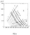
- Figure 5 is a work hardening diagram illustrating a new representation of the evolution of flow conditions in the right of way.
- Figure 6 illustrates the use of the diagram of hardening for the establishment of the equations of modelization.
- FIG. 1 shows schematically a cage rolling 1 consisting, as usual, of two spread columns 11 connected by crosspieces not represented and between which are placed several superimposed cylinders.
- the cage is quarto type and therefore includes two working cylinders 12, 12 'defining an air gap 10 of the passage of the product 2 to laminate and resting on the side opposite the product, respectively on two additional support cylinders 13, 13 ' large diameter.
- Each cylinder is rotatably mounted at its ends, on two pins carried by bearings mounted in chocks, respectively working 14, 14 ' and support 15, 15 '. These are threaded in windows provided on the two columns 11 of the cage and provided with guide faces along their sides from which slide the chocks of the cylinders, parallel to a clamping plane P in which are placed substantially the axes of the cylinders.
- the cage 1 is also associated with means product progress, for example, two roller tables 16, 16 'placed on either side of the cage in the case a reversible rolling mill.
- the rollers of the table rollers 16 placed upstream are rotated by in order to control the progress of product 2 which commits between the working cylinders 12 or 12 'and is driven by friction in the air gap 10. After reduction of its thickness, product 2 is received by the roller table downstream 16 '.
- the difference between the width of the air gap and the initial thickness of the product must be limited to avoid a refusal of engagement given the diameter of the cylinders 12, 12 'and of the thrust force exerted by the roller table 16.
- the cage is therefore provided with clamping means, for example jacks hydraulic or mechanical 17, mounted on each column 11 and bearing on the chocks 15 of the support cylinder upper 13, lower support chocks 15 ' can be simply supported by shims 18.
- clamping means for example jacks hydraulic or mechanical 17, mounted on each column 11 and bearing on the chocks 15 of the support cylinder upper 13, lower support chocks 15 ' can be simply supported by shims 18.
- the clamping means are jacks hydraulics 17 conventionally supplied by a circuit globally identified by reference 3, associated with a servovalve 31 controlled by a regulator 32.
- the regulator 32 is associated with position sensors 33 and position sensors pressure 34.
- the clamping means 17 can be controlled in position and pressure, so that determine, on the one hand the spacing e of the generators supporting working cylinders 12, 12 'determining the thickness of the air gap 10 and, on the other hand, the maintenance the spacing chosen during rolling, by application, between the cylinders, a clamping force called the force of rolling, which can be measured by the sensor 34.
- the spacing of the cylinders can also be regulated by separate cylinders, the cylinders clamping 17 then essentially serving to apply the rolling force to maintain the gap.
- the cage 1 is also provided with other sensors for measuring the various rolling parameters, by example of pyrometers 35, 35 'for temperature measurement of product 2, respectively before entering the cage and after leaving it, as well as means 36 of measurement of the speed of rotation of one of the cylinders work, to determine the speed of advancement of the produced in the right-of-way between the cylinders.
- the signals from all the sensors and corresponding to the measurements carried out are displayed in inputs of a measurement unit 4 which includes a calculation capable of developing a control signal from the regulator 32 for controlling the clamping means of so as to adjust and maintain the desired spacing between the working cylinders 12, 12 '.
- the calculation unit 4 comprises a calculator 40 associated with a programmed mathematical model of in order to calculate very precisely the rolling force to apply, from modeling equations representative of the behavior of the metal and, in particular, of its flow conditions in the right of way between the cylinders.
- FIG. 2 schematically illustrates the process of reducing the thickness of the metal product 2 between the two cylinders 12, 12 '.
- the product 2 comprises an upstream part 21, of thickness e x-1 , a central part 22 corresponding to the passage area between the cylinders which is limited by two contact arcs 20, 20 ', and a downstream part 23 having a thickness e x which, in practice, is slightly greater than the spacing e ' x of the working rolls 12, 12'.
- the roller table 16 determines the progress of the product to a speed V1 of engagement in the rolling mill.
- the end front of product 2 then comes into contact with the two cylinders 12, 12 '.
- the friction between the cylinder wall and the product determines its engagement in the grip between the cylinders, with thickness reduction and flow of metal. This results in a slight widening of the product but, essentially, an elongation of it, the amount of metal being retained. Therefore, the downstream part 23 of the product advances at a higher speed V2 to V1.
- the two cylinders 12, 12 ' are rotated at a certain angular speed and, conventionally, we distinguishes a neutral point 24 of the product for which the tangential forward speed V3 is equal to the speed peripheral cylinders 12, 12 '.
- the tangential speed of advancement of the product therefore increases gradually from V1 to V2. It is lower than V3 in upstream of the neutral section 24 and higher than V3 downstream.
- the friction factor Q f which is a function of the ratio of the length L of the contact arc 20 to the average thickness h of the product, can be estimated with fairly good accuracy.
- the outlet thickness e x is slightly greater than the actual thickness e ' x of the air gap between the cylinders, the difference being able to be determined in a known manner.
- the K factor depends on the temperature, the composition of the product and its structure but we observed that it was also necessary to involve phenomena complexes such as the evolution of the microstructure metallic during deformation.
- the object of the invention is a new process in which the overall rolling force to be applied can be more accurately determined by giving them ways to take into account the evolution of the microstructure crystal of the metal during rolling to estimate the value of the flow stress ⁇ of the metal at a time determined of the rolling.
- the depositor has conducted studies metallurgical very advanced with a large number laboratory experiments that have led to a new representation of the representative parameters of the intimate evolution of the microstructure of steel, allowing a modeling of this evolution according to overall rolling objectives (thickness reduction, flatness, temperature), this representation leading to modeling equations programmed in the model mathematical and likely to be integrated by the computer 40 associated with the central 4 for controlling rolling mill actuators.
- the method according to the invention makes it possible to take account changes in the metal flow conditions, a part during successive passes and on the other hand, the along the right-of-way, in the same pass.
- each elementary section M i corresponds to an elementary length of advance l i of the product between the cylinders, with an elementary deformation ⁇ i which is defined, in known manner, from the reduction of thickness e i-1 -e i to be carried out in the section considered, e i-1 being the thickness of the entry section of the section and e i the exit thickness.
- dislocations the metal hardens which translates into an increase in its dislocation density ⁇ .
- This quantity which can be measured on a sample metallic using an electron microscope in transmission, represents the cumulative length, per unit of volume of metal, linear crystal defects called dislocations.
- the invention makes it possible, on the contrary, to take account of the variation of the flow stress linked to the evolution of the microstructure during rolling and therefore provides the means to estimate much more specifies that previously the rolling force to be applied for obtain and maintain the desired thickness reduction at each pass.
- Figure 4 gives an example of this first diagram work hardening, each curve representing the variation of normalized rate of work hardening ⁇ * according to the stress of normalized flow ⁇ *, for a temperature T and a constant strain rate ⁇ ⁇ .
- each curve has at least two parts practically rectilinear, these rectilinear parts being, in each area, substantially parallel to each other.
- each type of steel corresponds to a specific diagram and in each diagram each curve and therefore each line corresponds to a temperature and at a determined rate of deformation but interpolations are possible.
- Each work hardening diagram, established from test results, corresponds to a steel of composition determined.
- FIGS. 3 to 6 have been drawn up experimentally for a steel having the following composition, in percentages by weight: C: 0.08; Mn: 1.1; If: 0.25; Fe: the rest.
- the parameters (11) on which the law of evolution depends of the model can be identified from tests, by example of homogeneous hot compression performed in laboratory, each at deformation speed and constant temperatures, so as to determine the curves representative stress-strain studies of behavior of steel under these conditions.
- the parameters k II , k III which are the slopes of the lines being used for the modelization of the law of hardening, respectively in domains II and III depend only on the composition of the steel and its grain size, ie the crystalline state which the metal has reached after the various successive rolling passes.
- the parameters x s2 , x s3 depend, moreover, on the strain rate ⁇ ⁇ and on the temperature T.
- the rate of deformation of the metal can be determined at each point of the right-of-way, depending on the reduction in thickness to be carried out and the speed of rolling.
- the mathematical model can estimate the product temperature and the rate of deformation in the section M i considered to deduce the right of the diagram of FIG. 6 and , the modeling equations (9, 10) applicable in this section, by making the interpolations necessary to take into account the temperature and the speed of deformation when these do not correspond to those of the tests.
- the computer can determine, for each slice M i , the predictable value ⁇ i of the flow stress corresponding to the deformation elementary ⁇ i to be produced and then draw from it the estimated value of elementary rolling force dF i to be applied in said slice M i .
- the computer can then, by integration, determine the overall rolling force F x to be applied to the whole of the right-of-way by the clamping means 27 during the pass x.
- the calculator takes into account mechanical and physical characteristics of the product, in particular of its elasticity, to determine the slight increase in the thickness of the product that is produced, known manner, at the exit of the rolling mill.
- the computer can therefore very precisely determine the air gap e ' x which will have to be adjusted and maintained between the working rolls 12, 12' to obtain the desired thickness reduction e x-1 -e x and controlling, during the pass considered, the adjustment of the clamping means, so as to apply between the rolls the rolling force actually necessary to maintain this air gap.
- a first method we performs tests on a selection of steels beforehand representative of a chemical composition domain for which one wishes to calibrate the model with, for each of them, different values of initial grain size, which determine the starting state of the microstructure of the metal.
- tests are carried out for different values temperature and strain rate so that cover an area of demand corresponding to efforts developed during the different passes of rolling and for which the model is established.
- the way the model takes into account the evolution of the metal structure also allows implement a simpler calibration method, by particular for laminating products made of steel leaving the field of chemical composition for which the model had been programmed.
- tests on test pieces are simply replaced by the first passes of rolling carried out on the product to be rolled with a setting manual.
- model math associated with the computer could be programmed, as indicated above, from tests carried out on a typical metal.
- the programmed equations are thus calibrated on the new metal depending on the behavior of it in rolling course, from the indications given by the passes manually adjusted.
- differential equations (10) and (11) established as indicated above allow, in because of their linear nature, to link in the two sense the deformation ⁇ to the flow stress ⁇ because they can be integrated in a sense, analytically, to express the deformation according to the stress, and the other way, digitally, to connect the strain stress.
- the computer can therefore recalculate the force to be applied between the cylinders under actual rolling conditions observed to compare it with the force measured during the same rolling pass.
- This comparison allows a adaptation of the game (12) of the parameters of the law of evolution defined by modeling equations and recalculate with these readjusted coefficients, the adjustment of the rolling mill for the next pass, and so on, for each pass of the rolling scheme initially planned by the strategy.
- the model can take into account the measurements performed during rolling to introduce factors of correction to the values of the parameters of the law evolution predetermined by laboratory data.
- the method according to the invention allows the calculation of the rolling diagram in order to modify it for the passes of reduction remaining to be executed, this readjustment operation and of verification being carried out during each pass of rolling until the final thickness is obtained.
- the method according to the invention is therefore applicable successively at the start of rolling then, at each step, by determining both the precision of the tolerances of the manufactured product as well as the optimization of the use of the industrial production tool.
- the process can be integrated into the strategy for calculating the rolling scheme using a method iterative optimization taking into account the data general of the installation and those of the product.
- the computer 40 before rolling, receives general data relating to product entering the rolling mill, the chemical composition of steel, gross product thickness, temperature at the entrance to the rolling mill, the final thickness targeted, etc. that the predictable flow stress and the force of lamination to be applied to achieve thickness reduction data can be accurately calculated it's possible, at each pass, to check if the reduction of thickness provided for by the rolling scheme leads to a excessive rolling force, requiring a decrease in this reduction in thickness or, on the contrary, if we can achieve greater thickness reduction leading to an acceptable rolling force.
- the calculator associated with the mathematical model can adapt the rolling scheme so as to use the capabilities of installation in optimal conditions, the model can effectively take into account, on each pass, the state of the product leaving the previous pass.
- the invention is not limited to details of the embodiments which have just been described, the process being adaptable to the circumstances in remaining within the protection framework defined by the claims.
- the figure shows a quarto rolling mill, the process being applicable in the same way to a duo, a sexto or any other type of hot rolling mill.
- the invention has been described for a rolling stand, but is applicable in the same way to all cages, reversible or not, a hot rolling installation, these cages can be insulated to constitute the rougher of a train to strips, hot or work in tandem, for example to constitute the finisher of the band train, or form a unit operating in continuous tandem.
- the idea of the invention being to estimate the metal flow stress using the knowledge acquired on the behavior of metals, such that the Taylor and Sims relationships or the Choquet model, we could obviously take advantage of the evolution of these knowledge to improve or modify the process by taking into account, in another way, the evolution of metal structure during deformation.
Abstract
Description
L'invention a pour objet un procédé de laminage d'un produit métallique et s'applique plus particulièrement au laminage à chaud de produits plats tels que des brames ou bandes issues d'un laminoir dégrossisseur ou de coulée continue.The subject of the invention is a method of rolling a metallic product and applies more particularly to hot rolling of flat products such as slabs or strips from a roughing or casting rolling mill keep on going.
Le laminage à chaud s'effectue habituellement par passes successives de laminage dans une installation comprenant une ou plusieurs cages de laminage. Chaque cage peut être utilisée comme un laminoir réversible effectuant un certain nombre de passes de réduction, alternativement dans un sens et dans l'autre, jusqu'à obtention de l'épaisseur désirée. Mais on peut aussi effectuer une seule passe de laminage dans chaque cage. L'installation fonctionne alors en laminoir tandem, le produit laminé étant pris simultanément dans toutes les cages et son épaisseur réduite successivement dans chaque cage.Hot rolling is usually done by successive rolling passes in an installation comprising one or more rolling stands. Each cage can be used as a reversible rolling mill performing a number of reduction passes, alternately back and forth, until you get the desired thickness. But we can also perform a single rolling pass in each cage. The installation then operates in a tandem rolling mill, the rolled product being taken simultaneously in all cages and its thickness successively reduced in each cage.
L'invention s'applique spécialement au laminage à chaud des aciers et de leurs alliages mais est également utilisable, dans certaines conditions, pour le laminage de métaux non-ferreux tel que l'aluminium et ses alliages.The invention applies especially to rolling with hot steels and their alloys but is also usable, under certain conditions, for the rolling of non-ferrous metals such as aluminum and its alloys.
D'une façon générale, un laminoir comprend une cage de maintien rigide ayant deux colonnes écartées entre lesquelles sont placés au moins deux cylindres de travail superposés qui définissent un entrefer de passage du produit à laminer. Dans une disposition classique dite quarto, les cylindres de travail prennent appui chacun sur un cylindre de soutien de plus grand diamètre. Dans un montage dit sexto, des cylindres intermédiaires sont interposés entre les cylindres de travail et les cylindres de soutien.Generally, a rolling mill includes a cage rigid support having two columns spaced between which are placed at least two working cylinders superimposed which define a product passage air gap to laminate. In a classic arrangement called quarto, the working cylinders are each supported on a cylinder larger diameter support. In a montage said sexto, intermediate cylinders are interposed between working cylinders and support cylinders.
Au moins les cylindres de soutien sont munis, à leurs extrémités, de tourillons tournant dans des empoises montées coulissantes dans des fenêtres ménagées respectivement sur les deux colonnes de la cage, parallèlement à un plan de serrage, généralement vertical, passant sensiblement par les axes des cylindres de travail. At least the support cylinders are provided, at their ends, of trunnions turning in chocks sliding mounted in fitted windows respectively on the two columns of the cage, parallel to a clamping plane, generally vertical, passing substantially through the axes of the working cylinders.
Le laminoir est associé à des moyens de commande du défilement du produit entre les cylindres, à une certaine vitesse d'avancement. Dans le cas d'un laminoir réversible, qui lamine alternativement dans deux sens opposés, les moyens de commande de l'avancement sont constitués, généralement, de deux tables à rouleaux, respectivement, une table à rouleaux placée en amont de la cage, dans le sens de défilement, pour commander l'engagement du produit et une autre table à rouleaux placée en aval pour recevoir le produit après laminage.The rolling mill is associated with means for controlling the scrolling of the product between the cylinders, at a certain forward speed. In the case of a reversible rolling mill, which alternately rolls in two opposite directions, advancement control means are constituted, usually two roller tables, respectively, one roller table placed upstream of the cage, in the direction of scroll, to order product engagement and a other roller table placed downstream to receive the product after rolling.
Dans le laminage à chaud, le produit est chauffé, avant le laminage, jusqu'à une température de l'ordre de 1200°C dans le cas de l'acier, de façon à faciliter la déformation du métal et son écoulement entre les cylindres. D'une façon générale, en effet, dans un processus de laminage, le produit présente à l'entrée de la cage une épaisseur supérieure à l'écartement des cylindres et, lorsqu'il vient au contact de ceux-ci, il est entraíné par frottement puis pincé entre les deux cylindres, avec écoulement du métal et réduction de l'épaisseur, jusqu'à une épaisseur sensiblement égale à l'écartement entre les génératrices en vis-à-vis des deux cylindres de travail. On peut ainsi définir une emprise de laminage délimitée par les arcs de contact entre chaque cylindre et le produit.In hot rolling, the product is heated, before rolling, up to a temperature of around 1200 ° C in the case of steel, so as to facilitate the deformation of the metal and its flow between the cylinders. Generally speaking, in fact, in a process of rolling, the product has a thickness greater than the spacing of the cylinders and, when it comes into contact with them, it is driven by friction then pinched between the two cylinders, with metal flow and thickness reduction, up to a thickness substantially equal to the spacing between the generators opposite the two working cylinders. We can thus define a rolling area defined by the contact arcs between each cylinder and the product.
Le laminage s'effectue donc à partir d'une pièce brute telle qu'une brame ou bande ayant une épaisseur variable qui peut aller de quelques millimètres à plusieurs centaines de millimètres et l'on réalise à chaque passe une réduction de l'épaisseur qui peut varier, par exemple, de 50 mm à quelques dizaines de millimètres.Laminating is therefore carried out from a part raw such as a slab or strip having a thickness variable which can range from a few millimeters to several hundreds of millimeters and a pass is made on each pass thickness reduction which can vary, for example, by 50 mm to a few tens of millimeters.
Pendant le laminage, les cylindres ont tendance à s'écarter l'un de l'autre et doivent donc être maintenus par une force de laminage opposée qui, dans un laminoir quarto est appliquée sur les empoises des cylindres de soutien.During rolling, the rolls tend to deviate from each other and must therefore be maintained by an opposite rolling force which in a quarto rolling mill is applied to the chocks of the support cylinders.
Ces moyens de serrage servent donc, d'une part au réglage préalable de l'écartement entre les cylindres et, d'autre part, au maintien de celui-ci pendant la passe de laminage. Ils sont généralement constitués de vis ou de vérins hydrauliques montés sur la cage et prenant appui respectivement sur les deux empoises d'un cylindre de soutien, l'autre étant bloqué en hauteur. Cependant, d'autres dispositions sont possibles. Par exemple, on peut utiliser des cylindres de soutien comportant une enveloppe montée rotative autour d'un arbre fixe et prenant appui sur celui-ci par l'intermédiaire d'une série de vérins. Ceux-ci constituent alors des moyens de serrage exerçant l'effort de laminage qui est ainsi réparti sur toute la longueur de l'entrefer.These clamping means therefore serve, on the one hand to prior adjustment of the spacing between the cylinders and, on the other hand, to the maintenance of it during the pass of rolling. They generally consist of screws or hydraulic cylinders mounted on the cage and supported respectively on the two chocks of a cylinder of support, the other being blocked in height. However, other arrangements are possible. For example, we can use support cylinders with an envelope rotatably mounted around a fixed shaft and supported by this via a series of cylinders. These then constitute clamping means exerting the force of rolling which is thus distributed over the entire length of the air gap.
Dans tous les cas, sous l'effet de la force de laminage, il se produit inévitablement une certain cédage des différents organes de la cage, qui augmente légèrement l'écartement des cylindres réglé à vide et a donc pour effet de diminuer l'écrasement prévu. Pour réaliser avec précision la réduction d'épaisseur souhaitée, il faut donc estimer la valeur du cédage, de façon à le compenser aussi exactement que possible.In any case, under the effect of the force of rolling, there is inevitably some yielding of the different organs of the cage, which increases slightly the spacing of the cylinders set when empty and therefore has the effect to reduce the planned crushing. To achieve precision the desired thickness reduction, it is therefore necessary to estimate the value of the surrender, so as to compensate it also exactly as possible.
La force de laminage à appliquer pour le maintien d'un écartement donné entre les cylindres dépend des conditions de déformation du produit dans l'emprise de passage entre les cylindres.The rolling force to be applied to maintain of a given spacing between the cylinders depends on the deformation conditions of the product in the grip of passage between the cylinders.
Inversement, la réduction d'épaisseur maximale possible est fonction de la force de laminage que l'on peut appliquer, compte tenu des capacités du laminoir.Conversely, the maximum thickness reduction possible is a function of the rolling force that we can apply, taking into account the capacities of the rolling mill.
La réduction d'épaisseur que l'on peut réaliser à chaque passe est donc limitée et c'est pourquoi le laminage d'un produit brut est réalisé, normalement, en plusieurs passes successives déterminant chacune une réduction d'épaisseur élémentaire compatible avec la capacité du laminoir. La réduction totale d'épaisseur à partir d'une épaisseur brute eo jusqu'à une épaisseur finale en peut s'obtenir en n passes suivant un processus de réduction d'épaisseur progressive, appelé schéma de laminage, qui dépend de la capacité du laminoir et des moyens de réglage dont on dispose, des caractéristiques mécaniques et physiques de la cage et du produit, ainsi que les tolérances à respecter en épaisseur et planéité.The reduction in thickness that can be achieved with each pass is therefore limited and this is why the rolling of a raw product is normally carried out in several successive passes, each determining an elementary thickness reduction compatible with the capacity. of the rolling mill. The total thickness reduction from a gross thickness e o to a final thickness e n can be obtained in n passes according to a process of progressive thickness reduction, called rolling scheme, which depends on the capacity of the rolling mill and the adjustment means available, the mechanical and physical characteristics of the stand and of the product, as well as the tolerances to be observed in terms of thickness and flatness.
En fonction des capacités de l'installation dont on dispose, on peut définir un schéma de laminage simple dans lequel on effectue, à chaque passe, une même réduction d'épaisseur moyenne. Le nombre de passes à effectuer dépend alors, simplement, de la réduction d'épaisseur totale à réaliser.Depending on the capacities of the installation which disposes, we can define a simple rolling scheme in which is carried out, at each pass, the same reduction of medium thickness. The number of passes to perform depends then, simply, from the total thickness reduction to achieve.
Cependant, on peut être ainsi amené à augmenter le nombre de passes nécessaire puisque la réduction d'épaisseur moyenne choisie doit être déterminée de façon à être compatible, pour toutes les passes, avec les caractéristiques du produit et de la cage. Or, pour améliorer la productivité, on a évidemment intérêt à diminuer, autant que possible, le nombre de passes à effectuer.However, it may be necessary to increase the number of passes required since the reduction in thickness chosen average must be determined so as to be compatible, for all passes, with product and cage characteristics. Now, for improve productivity, there is obviously an interest in reduce, as much as possible, the number of passes to carry out.
Mais on a observé également que la qualité finale du produit, et en particulier sa planéité, était liée aux conditions dans lesquelles est effectué le laminage et que tous les schémas de réduction d'épaisseur ne sont pas équivalents lorsque l'on veut obtenir un produit de qualité déterminée.But it was also observed that the final quality of the product, and in particular its flatness, was linked to conditions under which rolling is carried out and that not all thickness reduction schemes are equivalent when you want to get a quality product determined.
Par exemple, même si l'on peut définir une certaine température du produit au début du laminage, celle-ci varie d'une passe à la suivante. En effet, le produit se refroidit pendant le temps d'attente entre deux passes successives mais la déformation du métal entraine, inversement, un échauffement du produit lors de la passe et l'on peut être conduit à refroidir le produit entre deux passes pour éviter un échauffement cumulé trop important.For example, even if we can define a certain temperature of the product at the start of rolling, this varies from one pass to the next. Indeed, the product cools during the waiting time between two successive passes but the deformation of the metal leads, conversely, to a heating of the product during the pass and we can be leads to cooling the product between two passes to avoid too much cumulative heating.
Or, les conditions de déformation du produit, qui déterminent la force de laminage à appliquer, dépendent évidemment de la nature du métal et de sa température. However, the conditions of deformation of the product, which determine the rolling force to apply, depend obviously the nature of the metal and its temperature.
On a donc intérêt, pour obtenir un produit ayant des qualités déterminées, à suivre un schéma optimal qui dépend non seulement de la capacité mécanique de l'installation mais aussi de la qualité finale souhaitée pour le produit.We therefore have an interest in obtaining a product with determined qualities, to follow an optimal pattern which depends not only the mechanical capacity of the installation but also of the desired final quality for the product.
Depuis quelques années, on a cherché à réaliser une automatisation du processus de laminage d'un produit plat permettant d'obtenir l'épaisseur prévue avec une bonne planéité et en utilisant un nombre de passes minimum sans surcharger la ou les cages de laminage.In recent years, we have sought to achieve automation of the rolling process of a flat product to obtain the expected thickness with good flatness and using a minimum number of passes without overload the rolling stand (s).
Dans un tel système, il est nécessaire, de commander, à chaque passe, le réglage des moyens de serrage pour appliquer entre les cylindres de travail, une force de laminage permettant d'effectuer la réduction d'épaisseur maximale compatible avec la capacité du laminoir. Cette force de laminage est estimée en fonction des différents paramètres de laminage dont dépendent les conditions d'écoulement du métal dans l'emprise, notamment la réduction d'épaisseur à effectuer, la vitesse d'avancement et la température du produit à son entrée dans le laminoir.In such a system, it is necessary to control, at each pass, the adjustment of the clamping means to apply a force of lamination allowing thickness reduction maximum compatible with the capacity of the rolling mill. This rolling force is estimated based on the different rolling parameters on which the conditions depend metal flow in the right-of-way, in particular the reduction thickness to be performed, the speed of travel and the temperature of the product as it enters the rolling mill.
Selon la pratique connue jusqu'à présent dans les installations les plus perfectionnées, à partir de paramètres globaux comme, par exemple, la contrainte d'écoulement d'un métal en fonction de sa nuance et de sa température, on établit des tableaux de références des conditions de laminage observées auparavant pour un acier connu, de façon à en déduire les conditions à respecter lorsque le même acier se trouve une nouvelle fois dans le programme de production d'une installation.According to the practice known hitherto in the most advanced installations, from global parameters like, for example, the constraint flow of a metal according to its nuance and its temperature, reference tables of the rolling conditions previously observed for steel known, so as to deduce the conditions to be respected when the same steel is found again in the production program of an installation.
Pour cela, il faut faire une estimation de la force de laminage prévisible dans chaque cas. Cependant, celle-ci ne peut être appréciée que globalement à partir des observations faites lors des laminages précédents. Une telle estimation n'est pas assez précise pour régler les conditions de laminage au cours de chaque passe de façon à obtenir effectivement la réduction d'épaisseur optimale et, en particulier, assurer la compensation du cédage. For that, it is necessary to make an estimate of the force predictable rolling in each case. However, this can only be appreciated globally from observations made during previous rolling operations. A such an estimate is not precise enough to settle the rolling conditions during each pass so that effectively obtain the optimal thickness reduction and, in particular, ensure compensation for ceding.
L'invention remédie à cet inconvénient et a pour objet, grâce aux progrès de la modélisation, un nouveau procédé permettant de déterminer avec plus de précision la force de laminage à appliquer pour respecter un schéma de laminage. En outre, l'invention permet d'agir automatiquement et en temps réel sur les réglages du laminoir pour modifier ceux-ci à chaque passe en fonction des mesures effectuées à la passe précédente, de façon à adapter en permanence le schéma de laminage en optimisant les réglages à chaque passe.The invention remedies this drawback and has for object, thanks to advances in modeling, a new process for determining more precisely the rolling force to be applied to comply with a rolling. In addition, the invention makes it possible to act automatically and in real time on the settings of the rolling mill to modify these on each pass measurements made in the previous pass, so that continuously adapt the rolling scheme by optimizing the settings on each pass.
L'invention concerne donc d'une façon générale un procédé de laminage d'un produit métallique dans une installation comprenant :
- une cage de maintien ayant deux colonnes écartées,
- au moins deux cylindres de travail superposés entre les colonnes de la cage,
- des moyens de commande de l'avancement du produit avec laminage de celui-ci dans une emprise de laminage délimitée par deux arcs de contact du produit avec les deux cylindres, entre une section d'entrée et une section de sortie de l'emprise,
- des moyens de serrage prenant appui, respectivement, sur les cylindres et sur la cage, pour le réglage d'un écartement entre les cylindres de travail correspondant à une réduction d'épaisseur à réaliser et pour le maintien dudit écartement pendant la passe de laminage, par application, entre les cylindres de travail, d'une force de laminage qui dépend des caractéristiques mécaniques et physiques de la cage et du produit et des conditions d'écoulement du métal dans l'emprise de laminage, et détermine un effet de cédage des différents organes de la cage tendant à augmenter ledit écartement e,
- des moyens de réglage desdits moyens de serrage, commandés par un calculateur associé à un modèle mathématique.
- a support cage having two spaced apart columns,
- at least two working cylinders superimposed between the columns of the cage,
- means for controlling the progress of the product with rolling thereof in a rolling area delimited by two arcs of contact of the product with the two cylinders, between an inlet section and an outlet section of the area,
- clamping means bearing, respectively, on the rolls and on the stand, for adjusting a spacing between the working rolls corresponding to a reduction in thickness to be produced and for maintaining said spacing during the rolling pass, by applying, between the working rolls, a rolling force which depends on the mechanical and physical characteristics of the cage and the product and on the flow conditions of the metal in the rolling area, and determines a yielding effect of the different members of the cage tending to increase said spacing e,
- means for adjusting said clamping means, controlled by a computer associated with a mathematical model.
Conformément à l'invention, le calculateur associé au modèle mathématique détermine, avant chaque passe x, une valeur prévisible de la contrainte d'écoulement du métal correspondant à la déformation à réaliser dans la passe x considérée, en tenant compte de l'évolution, au cours du laminage, de la structure microcristalline du métal constituant le produit à laminer, et la force de laminage Fx à appliquer pour obtenir la réduction d'épaisseur souhaitée est calculée avant chaque passe x en fonction de la valeur ainsi prévue de la contrainte d'écoulement et de l'évolution de celle-ci pendant le laminage.In accordance with the invention, the computer associated with the mathematical model determines, before each pass x, a predictable value of the flow stress of the metal corresponding to the deformation to be carried out in the pass x considered, taking into account the evolution, during rolling, the microcrystalline structure of the metal constituting the product to be laminated, and the rolling force F x to be applied to obtain the desired thickness reduction is calculated before each pass x as a function of the value thus provided for the stress flow and its evolution during rolling.
De façon particulièrement avantageuse, la force de laminage Fx à appliquer pour une passe de laminage est calculée en tenant compte de la variation prévisible, le long de l'emprise, de la contrainte d'écoulement du métal au cours de ladite passe x.In a particularly advantageous manner, the rolling force F x to be applied for a rolling pass is calculated by taking account of the foreseeable variation, along the grip, of the flow stress of the metal during said pass x.
A cet effet, l'emprise de laminage est divisée en une série de p tranches élémentaires adjacentes Mi, M2, ...Mi, ...Mp, correspondant chacune à une longueur élémentaire d'avancement du produit entre les cylindres, avec une déformation élémentaire εi du produit dans chaque tranche Mi entre une section d'entrée d'épaisseur ei-1 et une section de sortie d'épaisseur ei, que, à partir des indications données par le modèle mathématique, le calculateur détermine, pour chaque tranche Mi, une valeur prévisible σi de la contrainte d'écoulement du métal, correspondant à ladite déformation élémentaire εi et en déduit la force de laminage élémentaire dFi à appliquer dans la tranche considérée Mi pour réaliser ladite déformation élémentaire εi et que, par intégration des forces élémentaires dFi dans les tranches successives M1, M2, ...Mi, ...Mp, le calculateur détermine la force de laminage globale à appliquer pour réaliser la réduction d'épaisseur souhaitée, et commande, en fonction de la force globale ainsi calculée, le réglage des moyens de serrage pour le maintien de l'écartement des cylindres permettant d'obtenir la réduction d'épaisseur ex-1-ex souhaitée, en tenant compte des conditions d'écoulement du métal le long de l'emprise et de l'effet de cédage résultant de ladite force globale.For this purpose, the rolling area is divided into a series of p adjacent elementary slices M i , M 2 , ... M i , ... M p , each corresponding to an elementary length of advance of the product between the cylinders, with an elementary deformation ε i of the product in each slice M i between an inlet section of thickness e i-1 and an outlet section of thickness e i , that, from the indications given by the mathematical model , the computer determines, for each slice M i , a predictable value σ i of the metal flow stress, corresponding to said elementary deformation ε i and deduces therefrom the elementary rolling force dF i to be applied in the slice considered Mi for carry out said elementary deformation ε i and that, by integration of the elementary forces dF i in the successive sections M 1 , M 2 , ... M i , ... M p , the computer determines the overall rolling force to be applied to achieve the desired thickness reduction, and controls, as a function of the overall force thus calculated, the adjustment of the clamping means for maintaining the spacing of the cylinders making it possible to obtain the desired thickness reduction e x-1 -e x , taking into account the flow conditions of the metal along the right-of-way and the yielding effect resulting from said overall force.
Il est à noter, cependant, que l'invention permet aussi de déterminer la force de laminage Fx à appliquer au cours d'une passe x en tenant compte de la valeur prévisible de la contrainte d'écoulement du métal résultant de l'évolution de l'état microcristallin du métal au cours des passes précédentes.It should be noted, however, that the invention also makes it possible to determine the rolling force F x to be applied during a pass x by taking into account the foreseeable value of the metal flow stress resulting from the evolution of the microcrystalline state of the metal during the previous passes.
Généralement, le laminage est effectué selon un schéma de laminage permettant de réaliser en n passes successives une réduction d'épaisseur globale eo-en, chaque passe x de laminage effectuant une réduction d'épaisseur ex-1-ex.Generally, the rolling is carried out according to a rolling scheme allowing an overall thickness reduction e o -e n to be carried out in n successive passes, each rolling pass x effecting a thickness reduction e x-1 -e x .
Selon une autre caractéristique de l'invention, le calculateur détermine, par itération, le schéma de laminage à respecter en calculant à l'avance, pour chaque passe x, la réduction d'épaisseur maximale conduisant à une force de laminage prévisible Fx compatible avec la capacité du laminoir, en fonction d'un ensemble de paramètres de laminage comprenant l'épaisseur et la température du produit et sa vitesse d'avancement avant l'entrée dans ladite passe x, de façon à tenir compte de l'évolution prévisible de la microstructure du métal d'une passe à la suivante.According to another characteristic of the invention, the calculator determines, by iteration, the rolling scheme to be observed by calculating in advance, for each pass x, the maximum thickness reduction leading to a force of predictable rolling Fx compatible with the capacity of the rolling mill, depending on a set of parameters rolling including product thickness and temperature and its forward speed before entering said pass x, so as to take into account the foreseeable evolution of the microstructure of the metal from one pass to the next.
En particulier, le calculateur peut être associé à des moyens de mesure en permanence, au cours de la passe, des valeurs effectives d'un ensemble de paramètres de laminage comprenant la force de laminage appliquée à chaque instant, la vitesse d'avancement du produit et la température de celui-ci respectivement à l'entrée et à la sortie du laminoir. Ainsi, à chaque passe x, le calculateur peut comparer ces valeurs effectives mesurées aux valeurs desdits paramètres prises en compte initialement pour ladite passe x dans la détermination du schéma de laminage, de façon à reprendre le calcul de celui-ci et introduire, en cas de besoin, des facteurs de correction aux paramètres pris en compte, afin d'adapter le schéma de laminage dans les passes suivantes.In particular, the computer can be associated with permanent measurement means, during the pass, effective values of a set of parameters of rolling including the rolling force applied to each instant, the speed of advancement of the product and the temperature thereof respectively at the inlet and at the exit from the rolling mill. So, at each pass x, the calculator can compare these actual measured values with the values said parameters taken into account initially for said pass x in determining the rolling pattern, so as to resume the calculation of it and introduce, in where necessary, correction factors to parameters taken into account, in order to adapt the rolling scheme in the following passes.
Dans un mode de réalisation préférentiel de l'invention, pour tenir compte de l'évolution de la structure microcristalline du métal au cours du laminage, on établit au moins une équation de modélisation valable pour une famille de métaux ayant un comportement microcristallin analogue, à partir d'essais de déformation à chaud effectués sur des éprouvettes d'au moins un métal-type de cette famille, lesdites équations dépendant d'un ensemble de paramètres liés à la composition du métal-type, on implante les équations initiales ainsi établies dans le modèle mathématique et, pour le laminage d'un produit constitué d'un métal de la même famille que le métal-type, on cale le modèle sur le métal à laminer en modifiant les paramètres desdites équations théoriques en fonction de résultats d'essais de déformation effectués sur un métal ayant une composition au moins voisine de celle du métal à laminer.In a preferred embodiment of the invention, to take account of the evolution of the microcrystalline structure of the metal during rolling, establish at least one modeling equation valid for a family of metals with microcrystalline behavior similar, from hot deformation tests carried out on test pieces of at least one standard metal of this family, said equations depending on a set of parameters related to the composition of the standard metal, we implant the initial equations thus established in the model mathematical and, for the rolling of a product of a metal of the same family as the standard metal, we wedge the model on the metal to be laminated by modifying the parameters said theoretical equations as a function of results deformation tests carried out on a metal having a composition at least close to that of the metal to be laminated.
De façon particulièrement avantageuse, pour définir les équations de modélisation, on détermine une grandeur intermédiaire liée à la vitesse de déformation du métal et variant de façon sensiblement linéaire en fonction de la contrainte d'écoulement dans au moins un domaine de déformation et, à partir d'essais de déformation réalisés pour une série de températures et de vitesses de déformation maintenues constantes, on établit un diagramme d'écrouissage sur lequel les variations de ladite grandeur intermédiaire peuvent être représentées approximativement, dans ledit domaine de déformation, par une famille de droites auxquelles correspond au moins une équation différentielle de forme linéaire, liant la déformation à la contrainte d'écoulement et pouvant être intégrée par le calculateur.Particularly advantageously, to define the modeling equations, we determine a quantity intermediate linked to the rate of deformation of the metal and varying substantially linearly depending on the flow constraint in at least one domain of deformation and, based on deformation tests carried out for a series of temperatures and strain rates maintained constant, one establishes a diagram of work hardening on which the variations of said intermediate quantity can be represented approximately, in said deformation domain, by a family of lines to which corresponds at least one differential equation linear, linking deformation to stress flow and can be integrated by the computer.
A partir d'un tel diagramme d'écrouissage, on peut établir au moins deux équations différentielles reliant la déformation à la contrainte d'écoulement, respectivement une première équation de forme linéaire donnant par intégration analytique, une expression de la déformation en fonction de la contrainte d'écoulement et une seconde équation susceptible d'être intégrée numériquement pour déterminer la contrainte d'écoulement prévisible correspondant à une déformation à réaliser.From such a work hardening diagram, one can establish at least two differential equations connecting the deformation to the flow stress, respectively a first linear equation giving by integration analytic, an expression of the strain as a function of flow constraint and a second equation likely to be digitally integrated to determine the predictable flow stress corresponding to a deformation to be achieved.
Dans un autre mode de réalisation, les équations de modélisation ayant été établies initialement pour un métal-type et implantées dans le modèle mathématique, ces équations peuvent être calées sur le métal à laminer, en réalisant tout d'abord au moins une passe de laminage, d'au moins un produit constitué du métal à laminer, dans au moins une cage de laminoir réglée de façon classique et en mesurant, au cours de chaque passe, d'une part la force de laminage réellement exercée et, d'autre part, les paramètres de laminage utilisés par le calculateur pour déterminer, à l'aide des équations de modélisation initiales, la force de laminage à exercer théoriquement. Par une méthode de régression numérique, on peut déterminer les modifications à apporter aux paramètres desdites équations initiales de façon à obtenir des équations de modélisation spécifiques au métal à laminer.In another embodiment, the equations of modeling having been established initially for a standard metal and implanted in the mathematical model, these equations can be calibrated on the metal to be laminated, first performing at least one rolling pass, at least at least one product consisting of the metal to be laminated, in at least a rolling stand, adjusted in a conventional manner and measuring, during each pass, on the one hand the force of rolling actually exercised and, on the other hand, the parameters used by the computer to determine, at using the initial modeling equations, the strength of lamination to exercise theoretically. By a method of numerical regression, we can determine the modifications to bring to the parameters of said initial equations of so as to obtain modeling equations specific to metal to be laminated.
L'invention couvre également une méthode particulièrement avantageuse pour exploiter les résultats d'essais de façon à établir les équations de modélisation. Dans une telle méthode, à partir de résultats d'essais de déformation effectués chacun à une température et à une vitesse de déformation constantes :
- on établit un premier diagramme d'écrouissage comportant une série de courbes représentatives, pour chaque température T, de la variation du taux d'écrouissage =dσ/dε en fonction de la contrainte d'écoulement σ,
- on transforme les données numériques relatives à chaque courbe pour établir un second diagramme d'écrouissage normalisé comportant une série de courbes représentatives de la variation, en fonction de la contrainte d'écoulement normalisée σ*=σ/µ(T), d'une grandeur intermédiaire 2*σ* égale au double du produit de ladite contrainte découlement normalisée, par le taux d'écrouissage normalisé * = /µ(T), µ(T) étant le module de cisaillement élastique à la température considérée,
- lesdites courbes ayant chacune au moins une partie sensiblement rectiligne située dans au moins un domaine II, III du diagramme, et lesdites parties rectilignes étant sensiblement parallèles dans chaque domaine,
- on modélise chaque partie sensiblement rectiligne
selon une première équation du type :
- et l'on effectue une intégration analytique de la
première équation de façon à établir, au moins pour chacun
des domaines II, III, une seconde équation de modélisation
- les paramètres k et k' étant déterminés, pour chacun des deux domaines II, III, à partir de la partie rectiligne d'une courbe du second diagramme d'écrouissage correspondant sensiblement à la température du métal et à la vitesse de déformation prévisibles à l'entrée de la cage.
- a first work hardening diagram is established comprising a series of curves representative, for each temperature T, of the variation in the work hardening rate = dσ / dε as a function of the flow stress σ,
- one transforms the numerical data relating to each curve to establish a second standard work hardening diagram comprising a series of curves representative of the variation, according to the normalized stress of flow σ * = σ / µ (T) , of a intermediate quantity 2 * σ * equal to twice the product of said normalized flow stress, by the normalized work hardening rate * = / µ (T) , µ (T) being the elastic shear modulus at the considered temperature,
- said curves each having at least one substantially rectilinear part situated in at least one domain II, III of the diagram, and said rectilinear parts being substantially parallel in each domain,
- each substantially rectilinear part is modeled according to a first equation of the type:
- and an analytical integration of the first equation is carried out so as to establish, at least for each of the domains II, III, a second modeling equation
- the parameters k and k 'being determined, for each of the two domains II, III, from the rectilinear part of a curve of the second work hardening diagram corresponding substantially to the temperature of the metal and to the rate of deformation predictable at l entrance to the cage.
Dans chacun des domaines II, III du diagramme d'écrouissage, les coefficients k et k' de la première équation de modélisation peuvent être déterminés par le calculateur en suivant une méthode de régression numérique, à partir de la température et des paramètres représentatifs de l'état cristallin du métal à l'entrée de la cage.In each area II, III of the diagram of hardening, the coefficients k and k 'of the first modeling equation can be determined by the calculator following a numerical regression method, from temperature and representative parameters the crystalline state of the metal at the entrance to the cage.
Pour tenir compte de l'évolution de la contrainte d'écoulement le long de l'emprise de laminage, celle-ci est divisée en une série de tranches successives M1, M2, ...Mi, ...Mp, correspondant chacune à une déformation élémentaire εi, et le calculateur détermine avant chaque passe, en fonction des paramètres de laminage mesurés à l'entrée de la cage, la contrainte d'écoulement prévisible σi dans chacune desdites tranches Mi par intégration numérique inverse de la seconde équation de modélisation en fonction de la déformation élémentaire εi à réaliser dans la tranche considérée Mi et en déduit la force de laminage élémentaire dFi à appliquer dans ladite tranche Mi, la force la laminage globale étant calculée par intégration desdites forces élémentaires le long de l'emprise.To take into account the evolution of the flow stress along the rolling right-of-way, it is divided into a series of successive sections M 1 , M 2 , ... M i , ... M p , each corresponding to an elementary deformation ε i , and the computer determines before each pass, as a function of the rolling parameters measured at the entry of the stand, the predictable flow stress σ i in each of said slices M i by digital integration inverse of the second modeling equation as a function of the elementary deformation ε i to be produced in the section considered M i and deduces therefrom the elementary rolling force dF i to be applied in said section M i , the overall rolling force being calculated by integration said elementary forces along the right-of-way.
L'invention couvre également de nombreuses autres caractéristiques avantageuses qui font l'objet des sous-revendications.The invention also covers many other advantageous features which are the subject of the subclaims.
Il est à noter que, du fait qu'il permet de calculer avec précision, et à tout moment du laminage, la valeur prévisible de la contrainte d'écoulement, le procédé selon l'invention peut s'intégrer à plusieurs niveaux dans le processus de laminage.It should be noted that, because it allows to calculate precisely, and at any time of rolling, the value predictable flow constraint, the process according to the invention can be integrated at several levels into the rolling process.
En particulier, les paramètres de laminage étant mesurés au cours de chaque passe de laminage, le calculateur peut vérifier si la force de laminage globale calculée en fonction de la réduction d'épaisseur prévue par le schéma de laminage est compatible avec les capacités de l'installation et si ladite réduction d'épaisseur prévue utilise, de façon optimale, lesdites capacités et modifier, en cas de besoin, le schéma de laminage pour les passes suivantes.In particular, the rolling parameters being measured during each rolling pass, the computer can check whether the overall rolling force calculated in as a function of the thickness reduction provided for in the diagram lamination is compatible with the capacities of the installation and if said expected thickness reduction uses, so said capacities and modify, if necessary, the rolling scheme for the following passes.
Mais l'invention sera mieux comprise par la description suivante d'un mode de réalisation particulier, donné à titre d'exemple et illustré par les dessins annexés. But the invention will be better understood by the following description of a particular embodiment, given by way of example and illustrated by the accompanying drawings.
La figure 1 représente schématiquement une cage de laminage associée à des moyens de contrôle du serrage selon l'invention.Figure 1 shows schematically a cage of rolling associated with tightening control means according to the invention.
La figure 2 illustre schématiquement le processus de laminage du produit entre deux cylindres de travail.Figure 2 schematically illustrates the process of rolling of the product between two working rolls.
La figure 3 est un diagramme indiquant l'évolution de la contrainte d'écoulement du métal laminé en fonction de la déformation dans l'emprise.Figure 3 is a diagram showing the evolution of the flow stress of the rolled metal as a function of the deformation in the grip.
La figure 4 est un diagramme représentant l'évolution du taux d'écrouissage du métal dans l'emprise en fonction de la contrainte d'écoulement.Figure 4 is a diagram showing the evolution of the rate of work hardening of the metal in the grip in function of the flow stress.
La figure 5 est un diagramme d'écrouissage illustrant une nouvelle représentation de l'évolution des conditions d'écoulement dans l'emprise.Figure 5 is a work hardening diagram illustrating a new representation of the evolution of flow conditions in the right of way.
La figure 6 illustre l'utilisation du diagramme d'écrouissage pour l'établissement des équations de modélisation.Figure 6 illustrates the use of the diagram of hardening for the establishment of the equations of modelization.
La figure 1 montre schématiquement une cage de laminage 1 constituée, comme habituellement, de deux colonnes écartées 11 reliées par des traverses non représentées et entre lesquelles sont placés plusieurs cylindres superposés. Dans l'exemple représenté, la cage est de type quarto et comprend donc deux cylindres de travail 12, 12' définissant un entrefer 10 du passage du produit 2 à laminer et prenant appui, du côté opposé au produit, respectivement sur deux cylindres de soutien 13, 13' de plus grand diamètre. Chaque cylindre est monté rotatif, à ses extrémités, sur deux tourillons portés par des paliers montés dans des empoises, respectivement de travail 14, 14' et de soutien 15, 15'. Celles-ci sont enfilées dans des fenêtres ménagées sur les deux colonnes 11 de la cage et munies, sur leurs côtés, de faces de guidage le long desquelles coulissent les empoises des cylindres, parallèlement à un plan de serrage P dans lequel sont placés sensiblement les axes des cylindres. Figure 1 shows schematically a cage rolling 1 consisting, as usual, of two spread columns 11 connected by crosspieces not represented and between which are placed several superimposed cylinders. In the example shown, the cage is quarto type and therefore includes two working cylinders 12, 12 'defining an air gap 10 of the passage of the product 2 to laminate and resting on the side opposite the product, respectively on two additional support cylinders 13, 13 ' large diameter. Each cylinder is rotatably mounted at its ends, on two pins carried by bearings mounted in chocks, respectively working 14, 14 ' and support 15, 15 '. These are threaded in windows provided on the two columns 11 of the cage and provided with guide faces along their sides from which slide the chocks of the cylinders, parallel to a clamping plane P in which are placed substantially the axes of the cylinders.
La cage 1 est également associée à des moyens d'avancement du produit, par exemple, deux tables à rouleaux 16, 16' placées de part et d'autre de la cage dans le cas d'un laminoir réversible. Les rouleaux de la table à rouleaux 16 placée en amont sont entraínés en rotation de façon à commander l'avancement du produit 2 qui s'engage entre les cylindres de travail 12 ou 12' et est entraíné par frottement dans l'entrefer 10. Après réduction de son épaisseur, le produit 2 est reçu par la table de rouleaux aval 16'.The cage 1 is also associated with means product progress, for example, two roller tables 16, 16 'placed on either side of the cage in the case a reversible rolling mill. The rollers of the table rollers 16 placed upstream are rotated by in order to control the progress of product 2 which commits between the working cylinders 12 or 12 'and is driven by friction in the air gap 10. After reduction of its thickness, product 2 is received by the roller table downstream 16 '.
Bien entendu, la différence entre la largeur de l'entrefer et l'épaisseur initiale du produit doit être limitée pour éviter un refus d'engagement compte tenu du diamètre des cylindres 12, 12' et de l'effort de poussée exercé par la table à rouleaux 16.Of course, the difference between the width of the air gap and the initial thickness of the product must be limited to avoid a refusal of engagement given the diameter of the cylinders 12, 12 'and of the thrust force exerted by the roller table 16.
Le laminage du produit 2 tend à écarter les cylindres de travail qui prennent appui sur les cylindres de soutien 13, 13'. Pour maintenir l'écartement, la cage est donc munie de moyens de serrage, par exemple des vérins hydrauliques ou mécaniques 17, montés sur chaque colonne 11 et prenant appui sur les empoises 15 du cylindre de soutien supérieur 13, les empoises de soutien inférieures 15' pouvant être simplement supportées par des cales 18.The rolling of product 2 tends to spread the working cylinders which rest on the cylinders of support 13, 13 '. To maintain the spacing, the cage is therefore provided with clamping means, for example jacks hydraulic or mechanical 17, mounted on each column 11 and bearing on the chocks 15 of the support cylinder upper 13, lower support chocks 15 ' can be simply supported by shims 18.
De préférence, les moyens de serrage sont des vérins hydrauliques 17 alimentés de façon classique par un circuit repéré globalement par la référence 3, associé à une servovalve 31 contrôlée par un régulateur 32. Le régulateur 32 est associé à des capteurs de position 33 et des capteurs de pression 34. De la sorte, les moyens de serrage 17 peuvent être contrôlés en position et en pression, de façon à déterminer, d'une part l'écartement e des génératrices d'appui des cylindres de travail 12, 12' déterminant l'épaisseur de l'entrefer 10 et, d'autre part, le maintien de l'écartement choisi pendant le laminage, par application, entre les cylindres, d'un effort de serrage appelé force de laminage, qui peut être mesuré par le capteur 34. Preferably, the clamping means are jacks hydraulics 17 conventionally supplied by a circuit globally identified by reference 3, associated with a servovalve 31 controlled by a regulator 32. The regulator 32 is associated with position sensors 33 and position sensors pressure 34. In this way, the clamping means 17 can be controlled in position and pressure, so that determine, on the one hand the spacing e of the generators supporting working cylinders 12, 12 'determining the thickness of the air gap 10 and, on the other hand, the maintenance the spacing chosen during rolling, by application, between the cylinders, a clamping force called the force of rolling, which can be measured by the sensor 34.
De façon connue, l'écartement des cylindres peut aussi être réglé par des vérins séparés, les vérins de serrage 17 servant alors, essentiellement, à appliquer la force de laminage pour le maintien de l'écartement.In known manner, the spacing of the cylinders can also be regulated by separate cylinders, the cylinders clamping 17 then essentially serving to apply the rolling force to maintain the gap.
Par ailleurs, la cage 1 est également munie d'autres capteurs de mesure des divers paramètres de laminage, par exemple des pyromètres 35, 35' de mesure de la température du produit 2, respectivement avant l'entrée dans la cage et après la sortie de celle-ci, ainsi que des moyens 36 de mesure de la vitesse de rotation de l'un des cylindres de travail, permettant de déterminer la vitesse d'avancement du produit dans l'emprise de passage entre les cylindres.Furthermore, the cage 1 is also provided with other sensors for measuring the various rolling parameters, by example of pyrometers 35, 35 'for temperature measurement of product 2, respectively before entering the cage and after leaving it, as well as means 36 of measurement of the speed of rotation of one of the cylinders work, to determine the speed of advancement of the produced in the right-of-way between the cylinders.
Les signaux émis par tous les capteurs et correspondant aux mesures effectuées sont affichés aux entrées d'une centrale de mesure 4 qui comporte une unité de calcul capable d'élaborer un signal de commande du régulateur 32 pour la commande des moyens de serrage de façon à régler et à maintenir l'écartement souhaité entre les cylindres de travail 12, 12'.The signals from all the sensors and corresponding to the measurements carried out are displayed in inputs of a measurement unit 4 which includes a calculation capable of developing a control signal from the regulator 32 for controlling the clamping means of so as to adjust and maintain the desired spacing between the working cylinders 12, 12 '.
Selon l'invention, l'unité de calcul 4 comprend un calculateur 40 associé à un modèle mathématique programmé de façon à calculer de façon très précise la force de laminage à appliquer, à partir d'équations de modélisation représentatives du comportement du métal et, en particulier, de ses conditions d'écoulement dans l'emprise entre les cylindres.According to the invention, the calculation unit 4 comprises a calculator 40 associated with a programmed mathematical model of in order to calculate very precisely the rolling force to apply, from modeling equations representative of the behavior of the metal and, in particular, of its flow conditions in the right of way between the cylinders.
La figure 2 illustre schématiquement le processus de réduction d'épaisseur du produit métallique 2 entre les deux cylindres 12, 12'. D'une façon générale, le produit 2 comprend une partie amont 21, d'épaisseur ex-1, une partie centrale 22 correspondant à l'emprise de passage entre les cylindres qui est limitée par deux arcs de contact 20, 20', et une partie aval 23 ayant une épaisseur ex qui, en pratique, est un peu supérieure à l'écartement e'x des cylindres de travail 12, 12'. FIG. 2 schematically illustrates the process of reducing the thickness of the metal product 2 between the two cylinders 12, 12 '. In general, the product 2 comprises an upstream part 21, of thickness e x-1 , a central part 22 corresponding to the passage area between the cylinders which is limited by two contact arcs 20, 20 ', and a downstream part 23 having a thickness e x which, in practice, is slightly greater than the spacing e ' x of the working rolls 12, 12'.
La table à rouleaux 16 dont les rouleaux sont entraínés en rotation, détermine l'avancement du produit à une vitesse V1 d'engagement dans le laminoir. L'extrémité avant du produit 2 vient alors au contact des deux cylindres 12, 12'. Le frottement entre la paroi des cylindres et le produit détermine l'engagement de celui-ci dans l'emprise entre les cylindres, avec réduction d'épaisseur et écoulement du métal. Il en résulte un léger élargissement du produit mais, essentiellement, un allongement de celui-ci, la quantité de métal étant conservée. Par conséquent, la partie aval 23 du produit avance à une vitesse V2 supérieure à V1. Les deux cylindres 12, 12' sont entraínés en rotation à une certaine vitesse angulaire et, de façon classique, on distingue un point neutre 24 du produit pour lequel la vitesse tangentielle d'avancement V3 est égale à la vitesse périphérique des cylindres 12, 12'. Le long des deux arcs de contact 20, 20' entre le produit et les cylindres, la vitesse tangentielle d'avancement du produit augmente donc progressivement de V1 à V2. Elle est inférieure à V3 en amont de la section neutre 24 et supérieure à V3 en aval.The roller table 16 whose rollers are driven in rotation, determines the progress of the product to a speed V1 of engagement in the rolling mill. The end front of product 2 then comes into contact with the two cylinders 12, 12 '. The friction between the cylinder wall and the product determines its engagement in the grip between the cylinders, with thickness reduction and flow of metal. This results in a slight widening of the product but, essentially, an elongation of it, the amount of metal being retained. Therefore, the downstream part 23 of the product advances at a higher speed V2 to V1. The two cylinders 12, 12 'are rotated at a certain angular speed and, conventionally, we distinguishes a neutral point 24 of the product for which the tangential forward speed V3 is equal to the speed peripheral cylinders 12, 12 '. Along the two arches of contact 20, 20 'between the product and the cylinders, the tangential speed of advancement of the product therefore increases gradually from V1 to V2. It is lower than V3 in upstream of the neutral section 24 and higher than V3 downstream.
La valeur des frottements à l'interface entre le produit et les cylindres varie donc tout au long de l'arc de contact 20, la vitesse relative étant elle-même variable et s'annulant au niveau de la section neutre 24.The value of friction at the interface between the product and the cylinders therefore varies throughout the arc of contact 20, the relative speed itself being variable and canceling out at the neutral section 24.
On sait que la force de laminage par unité de
largeur peut être calculée par la relation de Sims :
On peut estimer avec une assez bonne précision le facteur de frottement Qf qui est fonction du rapport de la longueur L de l'arc de contact 20 à l'épaisseur moyenne h du produit.The friction factor Q f, which is a function of the ratio of the length L of the contact arc 20 to the average thickness h of the product, can be estimated with fairly good accuracy.
On a donc
Ces grandeurs peuvent être calculées de façon connue à partir du rayon des cylindres de travail, de l'épaisseur du produit à l'entrée de la cage et de l'écartement des cylindres à la sortie de l'emprise.These quantities can be calculated in a known manner from the radius of the working rolls, from the thickness of product at the entrance of the cage and the spacing of cylinders at the exit of the right-of-way.
Comme on l'a indiqué, en raison d'un certain degré d'élasticité du métal, l'épaisseur de sortie ex est un peu supérieure à l'épaisseur réelle e'x de l'entrefer entre les cylindres, la différence pouvant être déterminée de façon connue.As indicated, due to a certain degree of elasticity of the metal, the outlet thickness e x is slightly greater than the actual thickness e ' x of the air gap between the cylinders, the difference being able to be determined in a known manner.
Le facteur K dépend de la température, de la composition du produit et de sa structure mais on a observé qu' il fallait aussi faire intervenir des phénomènes complexes tels que l'évolution de la microstructure métallique au cours de la déformation.The K factor depends on the temperature, the composition of the product and its structure but we observed that it was also necessary to involve phenomena complexes such as the evolution of the microstructure metallic during deformation.
Comme indiqué plus haut, même dans les installations perfectionnées, on se bornait jusqu'à présent, à mettre en mémoire des paramètres globaux, déterminant les conditions de déformation du produit en fonction de la nuance de l'acier, de façon à établir un tableau de référence des conditions de laminage pour un acier connu. On pouvait alors reprendre les mêmes paramètres lorsque les mêmes aciers se retrouvaient dans le carnet de production de l'installation de laminage. Cependant, il fallait, pour cela, estimer la valeur moyenne de la contrainte d'écoulement σ pour en déduire le facteur K, de façon à calculer la force de laminage en appliquant la relation de Sims.As indicated above, even in installations perfected, so far we have limited ourselves to putting in memory of the global parameters, determining the conditions deformation of the product depending on the nuance of steel, so as to establish a reference table of rolling conditions for a known steel. We could then use the same parameters when the same steels found in the installation production book rolling. However, for that, it was necessary to estimate the mean value of the flow stress σ for in deduce the factor K, so as to calculate the force of rolling by applying the Sims relation.
En outre, dans le cas d'aciers n'ayant pas été précédemment laminés, on ne pouvait procéder que par approximation.In addition, in the case of steels which have not been previously rolled, we could only proceed by approximation.
L'invention a pour objet, au contraire, un nouveau procédé dans lequel la force de laminage globale à appliquer peut être déterminée de façon plus exacte en se donnant les moyens de tenir compte de l'évolution de la microstructure cristalline du métal au cours du laminage pour estimer la valeur de la contrainte d'écoulement σ du métal à un moment déterminé du laminage. The object of the invention, on the contrary, is a new process in which the overall rolling force to be applied can be more accurately determined by giving them ways to take into account the evolution of the microstructure crystal of the metal during rolling to estimate the value of the flow stress σ of the metal at a time determined of the rolling.
Pour cela, le déposant a mené des études métallurgiques très poussées avec un grand nombre d'expériences en laboratoire qui ont conduit à une représentation nouvelle des paramètres représentatifs de l'évolution intime de la microstructure de l'acier, permettant une modélisation de cette évolution selon les objectifs globaux du laminage (réduction d'épaisseur, planéité, température), cette représentation conduisant à des équations de modélisation programmées dans le modèle mathématique et susceptibles d'être intégrées par le calculateur 40 associé à la centrale 4 de commande des actionneurs du laminoir.For this, the depositor has conducted studies metallurgical very advanced with a large number laboratory experiments that have led to a new representation of the representative parameters of the intimate evolution of the microstructure of steel, allowing a modeling of this evolution according to overall rolling objectives (thickness reduction, flatness, temperature), this representation leading to modeling equations programmed in the model mathematical and likely to be integrated by the computer 40 associated with the central 4 for controlling rolling mill actuators.
On a ainsi pu mettre au point un procédé de réglage des moyens de serrage intégrant la modélisation ainsi développée de façon à appliquer entre les cylindres la force de laminage exactement nécessaire.We were thus able to develop an adjustment process clamping means integrating modeling as well developed to apply the force between the cylinders exactly needed.
De plus, un tel procédé permet également d'adapter le schéma de laminage aux conditions observées à chaque passe et, ainsi, de suivre un schéma de laminage optimal.In addition, such a method also makes it possible to adapt the rolling scheme under the conditions observed at each pass and thus follow an optimal rolling pattern.
Le procédé selon l'invention permet de tenir compte de l'évolution des conditions d'écoulement du métal, d'une part au cours des passes successives et d'autre part, le long de l'emprise, au cours d'une même passe.The method according to the invention makes it possible to take account changes in the metal flow conditions, a part during successive passes and on the other hand, the along the right-of-way, in the same pass.
A cet effet, l'emprise de laminage est divisée en une série de p tranches élémentaires adjacentes M1, M2, ...Mi, ...Mp. Comme indiqué schématiquement sur la figure 2, chaque tranche élémentaire Mi correspond à une longueur élémentaire d'avancement li du produit entre les cylindres, avec une déformation élémentaire εi que l'on définit, de façon connue, à partir de la réduction d'épaisseur ei-1-ei à effectuer dans la tranche considérée, ei-1 étant l'épaisseur de la section d'entrée de la tranche et ei l'épaisseur de sortie.To this end, the rolling area is divided into a series of p adjacent elementary slices M 1 , M 2 , ... M i , ... M p . As shown diagrammatically in FIG. 2, each elementary section M i corresponds to an elementary length of advance l i of the product between the cylinders, with an elementary deformation ε i which is defined, in known manner, from the reduction of thickness e i-1 -e i to be carried out in the section considered, e i-1 being the thickness of the entry section of the section and e i the exit thickness.
Selon la température T du métal, la déformation ε correspondant à la réduction d'épaisseur demandée au niveau considéré de l'emprise et la vitesse de déformation ε ˙ = dε/dt, divers phénomènes métallurgiques peuvent se produire au cours de l'avancement du produit dans l'emprise.According to the temperature T of the metal, the deformation ε corresponding to the thickness reduction requested at the level considered of the grip and the speed of deformation ε ˙ = dε / dt, various metallurgical phenomena can occur during the advancement of the product in the right of way.
Ces phénomènes, qui ont été décrits dans diverses études récentes, peuvent être résumés ainsi qu'il suit :These phenomena, which have been described in various recent studies, can be summarized as follows:
Tout d'abord, on constate, un écrouissage du métal qui traduit une augmentation de sa densité de dislocation ρ. Cette grandeur, qui peut être mesurée sur un échantillon métallique à l'aide d'un microscope électronique en transmission, représente la longueur cumulée, par unité de volume du métal, de défauts cristallins linéaires appelés dislocations.First of all, we note that the metal hardens which translates into an increase in its dislocation density ρ. This quantity, which can be measured on a sample metallic using an electron microscope in transmission, represents the cumulative length, per unit of volume of metal, linear crystal defects called dislocations.
On sait que la densité de dislocation, qui est
couramment évaluée en mètres par mètre cube, est liée à la
contrainte d'écoulement σ par la relation de Taylor :
Ensuite, on observe que, très rapidement, alors que l'écrouissage se poursuit, il se produit également un phénomène dit de restauration, qui tend à diminuer la densité de dislocation ρ par annihilation mutuelle de dislocations voisines.Then we observe that, very quickly, while work hardening continues, there is also a so-called restoration phenomenon, which tends to decrease the dislocation density ρ by mutual annihilation of neighboring dislocations.
De plus, pour la plupart des aciers, il peut se produire, au-delà d'une certaine déformation, un phénomène dit de recristallisation dynamique, qui tend à diminuer la densité de dislocation ρ. In addition, for most steels, it can produce, beyond a certain deformation, a phenomenon called dynamic recrystallization, which tends to decrease the dislocation density ρ.
On a donc eu l'idée qu'en tenant compte de ces phénomènes, on pourrait analyser le comportement du métal au cours d'une déformation de façon à en déduire une estimation assez précise de la valeur prévisible de la contrainte d'écoulement, qui est le premier facteur dont dépend la force de laminage et qui évolue constamment d'une passe à la suivante et même au cours d'une passe, le long de l'emprise de passage du produit entre les cylindres.So we had the idea that taking into account these phenomena, we could analyze the behavior of metal at during a deformation so as to deduce an estimate fairly precise predictable value of the constraint of flow, which is the first factor on which the rolling force and which is constantly changing from one pass to the next and even during a pass, along the right-of-way passage of the product between the cylinders.
C'est précisément, cette évolution qui n'avait pas été prise en compte jusqu'à présent, la force de laminage étant calculée à partir d'une valeur moyenne de la contrainte d'écoulement appréciée globalement pour l'ensemble de l'emprise.It is precisely this evolution which had not taken into account so far, the rolling force being calculated from an average value of the flow stress appreciated overall for the whole of the right-of-way.
L'invention permet, au contraire, de tenir compte de la variation de la contrainte d'écoulement liée à l'évolution de la microstructure au cours du laminage et donne donc les moyens d'estimer de façon beaucoup plus précise qu'auparavant la force de laminage à appliquer pour obtenir et maintenir la réduction d'épaisseur souhaitée à chaque passe.The invention makes it possible, on the contrary, to take account of the variation of the flow stress linked to the evolution of the microstructure during rolling and therefore provides the means to estimate much more specifies that previously the rolling force to be applied for obtain and maintain the desired thickness reduction at each pass.
Pour cela, on a étudié de façon approfondie le comportement de l'acier en traçant des courbes expérimentales à partir desquelles, on a pu établir des équations de modélisation susceptibles d'être implantées dans un modèle mathématique associé à un calculateur de commande du laminoir, de façon que celui-ci puisse calculer la force de laminage à appliquer pour chaque passe en fonction d'un ensemble de paramètres estimés ou mesurés.For this, we studied in depth the behavior of steel when drawing curves from which we were able to establish modeling equations likely to be implemented in a mathematical model associated with a calculator control of the rolling mill so that it can calculate the rolling force to be applied for each pass in function of a set of estimated or measured parameters.
Les étapes du procédé selon l'invention sont illustrées par les figures 3 à 6.The steps of the method according to the invention are illustrated in Figures 3 to 6.
L'évolution de la contrainte d'écoulement σ ressort du diagramme de la figure 3 qui indique, pour différentes températures T1, T2,..., les variations de la valeur courante dans l'emprise de la contrainte d'écoulement σ, indiquée en ordonnée, en fonction de la déformation cumulée ε indiquée en abscisse en supposant, ce qui est proche de la réalité, que la déformation ε et la température T varient à des vitesses, respectivement ε ˙ = dε/dt et T ˙ = dT/dt sensiblement constantes le long de l'emprise.The evolution of the flow stress σ comes out of the diagram of figure 3 which indicates, for different temperatures T1, T2, ..., variations in the current value in the grip of the flow stress σ, indicated in ordinate, according to the cumulated deformation ε indicated on the abscissa assuming, which is close to reality, that the deformation ε and the temperature T vary at velocities, respectively ε ˙ = dε / dt and T ˙ = dT / dt substantially constants along the right of way.
Les courbes de la figure 3 ont été établies à partir d'expériences de laboratoire, par exemple des essais de compression homogène à chaud effectués, à des températures T1, T2... sur des éprouvettes d'un même métal.The curves in Figure 3 were established from laboratory experiments, for example tests of homogeneous hot compression performed at temperatures T1, T2 ... on test pieces of the same metal.
On a observé que, pour rendre compte du comportement du métal, il était intéressant d'utiliser, comme variable intermédiaire, le taux d'écrouissage = dσ /dε qui, pour une déformation et une température donnée, correspond à la pente d'une des courbes de la figure 3.It has been observed that, to account for behavior of metal, it was interesting to use, as a variable intermediate, the rate of work hardening = dσ / dε which, for a given deformation and temperature, corresponds to the slope of one of the curves in Figure 3.
Pour interpréter les phénomènes physiques gérant la déformation du métal, on va donc tracer un premier diagramme d'écrouissage représentant l'évolution du taux d'écrouissage en fonction de la contrainte d'écoulement σ.To interpret the physical phenomena managing the metal deformation, so we will draw a first diagram of work hardening representing the evolution of the rate of work hardening as a function of the flow stress σ.
Cependant, on préfère utiliser les grandeurs normées
La figure 4 donne un exemple de ce premier diagramme d'écrouissage, chaque courbe représentant la variation du taux d'écrouissage normalisé * en fonction de la contrainte d'écoulement normalisée σ*, pour une température T et une vitesse de déformation ε ˙ constantes.Figure 4 gives an example of this first diagram work hardening, each curve representing the variation of normalized rate of work hardening * according to the stress of normalized flow σ *, for a temperature T and a constant strain rate ε ˙.
On constate que la forme des courbes ainsi obtenue évolue lorsque la vitesse de déformation et la température varient.It can be seen that the shape of the curves thus obtained changes when the rate of deformation and the temperature vary.
Pour la mise en oeuvre de l'invention, on a alors eu l'idée de transformer les données numériques ayant permis d'obtenir les courbes de la figure 4, par un changement de variable susceptible de conduire à des courbes utilisables pour une modélisation simple dans un calculateur.For the implementation of the invention, we then had the idea of transforming the digital data that allowed to obtain the curves of figure 4, by a change of variable likely to lead to usable curves for simple modeling in a computer.
Il est apparu, en effet, qu'il est particulièrement avantageux, d'utiliser comme variable intermédiaire le produit 2*.σ* du double du taux d'écrouissage normalisé par la contrainte d'écoulement normalisée. It appeared, in fact, that it is particularly advantageous, to use as an intermediate variable the product 2 * .σ * of twice the rate of work hardening normalized by the normalized flow stress.
On obtient ainsi un second diagramme d'écrouissage, représenté sur la figure 5, qui indique la variation de la grandeur 2*.σ*, indiquée en ordonnée, en fonction de la contrainte d'écoulement normalisée σ* indiquée en abscisse.We thus obtain a second work hardening diagram, represented in figure 5, which indicates the variation of the size 2 * .σ *, indicated on the ordinate, depending on the normalized flow stress σ * indicated on the abscissa.
Comme précédemment, on se place à température et vitesse de déformation constantes, la transformation étant effectuée pour chaque courbe.As before, we place ourselves at temperature and constant strain rate, the transformation being performed for each curve.
A titre d'exemple, sur le second diagramme d'écrouissage de la figure 5, on a indiqué en haut à droite la vitesse de déformation ε ˙ et la température T auxquelles correspondent les courbes du diagramme. On distingue ainsi différents groupes de courbes expérimentales. Par exemple, sur le diagramme, on a tracé de façon différente, quatre courbes 51, 52, 53, 54 correspondant, respectivement, à des températures de 885°C, 935°C, 985°C, 1035°C, pour une même vitesse de déformation ε ˙ = 3,6 s-1 et cinq courbes 50', 51', 52', 53', 54', 55', correspondant respectivement à des températures de 835°C, 885°C, 935°C, 985°C, 1035°C, pour une vitesse de déformation ε ˙ = 0,36 s-1 dix fois moins importante.By way of example, on the second work hardening diagram of FIG. 5, one indicated at the top right the strain rate ε auxquelles and the temperature T to which correspond the curves of the diagram. There are thus different groups of experimental curves. For example, on the diagram, we have drawn differently, four curves 51, 52, 53, 54 corresponding, respectively, to temperatures of 885 ° C, 935 ° C, 985 ° C, 1035 ° C, for the same strain rate ε ˙ = 3.6 s -1 and five curves 50 ', 51', 52 ', 53', 54 ', 55', corresponding respectively to temperatures of 835 ° C, 885 ° C, 935 ° C , 985 ° C, 1035 ° C, for a deformation speed ε ˙ = 0.36 s -1 ten times less.
On constate que, de façon particulièrement avantageuse, dans ce nouveau domaine de représentation (2*.σ*, σ*), chaque courbe comporte au moins deux parties pratiquement rectilignes, ces parties rectilignes étant, dans chaque domaine, sensiblement parallèles entre elles.We note that, particularly advantageous in this new field of representation (2 * .σ *, σ *), each curve has at least two parts practically rectilinear, these rectilinear parts being, in each area, substantially parallel to each other.
Comme l'indique la figure 6, on peut ainsi distinguer, dans le second diagramme écrouissage-déformation, deux domaines II et III qui couvrent la plus grande partie du domaine utile de la déformation et dans lesquels la grandeur 2*.σ* varie de façon sensiblement linéaire en fonction de la contrainte d'écoulement normalisée σ*. Le domaine IV non linéaire correspond à l'apparition et au développement de la recristallisation dynamique.As shown in Figure 6, we can thus distinguish, in the second hardening-strain diagram, two domains II and III which cover the most large part of the useful range of deformation and in which the magnitude 2 * .σ * varies significantly linear as a function of the flow stress normalized σ *. The nonlinear domain IV corresponds to the appearance and development of recrystallization dynamic.
Bien entendu, à chaque type d'acier correspond un diagramme spécifique et, dans chaque diagramme, chaque courbe et, par conséquent, chaque droite correspond à une température et à une vitesse de déformation déterminées mais des interpolations sont possibles.Of course, each type of steel corresponds to a specific diagram and in each diagram each curve and therefore each line corresponds to a temperature and at a determined rate of deformation but interpolations are possible.
Pour modéliser ces courbes, il est avantageux de prendre comme variable intermédiaire la densité de dislocation ρ définie plus haut.To model these curves, it is advantageous to take the density of dislocation ρ defined above.
En effet, la différenciation de l'équation (3) dite
de Taylor donne :
Etant donné que, dans chacun des deux domaines II et III de la figure 6, la grandeur 2* σ* varie de façon sensiblement linéaire en fonction de σ*, les droites de la figure 6 peuvent approximativement être substituées aux courbes de la figure 5.Given that in each of the two areas II and III of figure 6, the quantity 2 * σ * varies so substantially linear as a function of σ *, the straight lines of the figure 6 can roughly be substituted for curves of figure 5.
Ces courbes étant sensiblement parallèles, on peut
écrire l'équation des droites sous la forme linéaire
suivante :
Les deux familles de droites correspondant à l'acier
considéré, qui ont des pentes différentes, respectivement
kII et kIII pour chacun des deux domaines II et III où le
comportement est linéaire, sont donc représentées par des
équations qui peuvent être programmées dans le modèle
mathématique associé au calculateur 40. Celui-ci peut alors,
par des méthodes mathématiques connues, réaliser une
intégration analytique de l'équation (9) qui conduit, pour
chaque domaine II, III à une expression de la déformation ε
de la forme :
La valeur initiale de la contrainte d'écoulement dans le domaine II et la continuité aux points de jonction entre deux droites correspondantes dans les domaines II et III permet de déterminer les valeurs des constantes d'intégration λII et λIII correspondant respectivement aux domaines II et III.The initial value of the flow stress in domain II and the continuity at the junction points between two corresponding straight lines in domains II and III makes it possible to determine the values of the integration constants λ II and λ III corresponding respectively to domains II and III.
Il est à noter que, pour simplifier, on a fait dépendre la loi d'évolution d'un jeu minimal de quatre paramètres kII, kIII, xs2, xs3 (11).It should be noted that, for simplicity, the law of evolution has been made to depend on a minimum set of four parameters k II , k III , x s2 , x s3 (11).
Cependant, ces paramètres pourraient être plus nombreux, de façon à tenir compte des relations entre eux.However, these parameters could be more many, so as to take into account the relationships between them.
Chaque diagramme d'écrouissage, établi à partir de résultats d'essais, correspond à un acier de composition déterminée.Each work hardening diagram, established from test results, corresponds to a steel of composition determined.
A titre d'exemple, les diagrammes des figures 3 à 6
ont été établis expérimentalement pour un acier ayant la
composition suivante, en pourcentages en poids :
C :0,08 ; Mn :1,1 ; Si :0,25 ; Fe : le reste.By way of example, the diagrams in FIGS. 3 to 6 have been drawn up experimentally for a steel having the following composition, in percentages by weight:
C: 0.08; Mn: 1.1; If: 0.25; Fe: the rest.
On voit, sur la figure 6 que, par exemple dans le domaine II, pour chaque vitesse de déformation ε ˙, on peut établir les équations d'une famille de droites parallèles 61, 62, 63, 34 correspondant à diverses températures de déformation, 885°, 935°, 985° et 1035°.We see in Figure 6 that, for example in the domain II, for each strain rate ε ˙, we can establish the equations of a family of parallel lines 61, 62, 63, 34 corresponding to various temperatures of deformation, 885 °, 935 °, 985 ° and 1035 °.
Il en est de même- dans le domaine III et pour d'autres vitesses de déformation.The same is true - in area III and for other rates of deformation.
Dans l'exposé du procédé qui va suivre, on suppose que, connaissant la composition de l'acier à laminer, on a pu, à partir d'essais préalables, déterminer les équations de modélisation correspondant au comportement de cet acier pour certaines vitesses de déformation et à diverses températures. Ces équations de modélisation sont donc implantées dans le modèle mathématique associé au calculateur 40 qui pourra ainsi, pour un produit constitué du même métal, définir l'équation de modélisation applicable à un moment considéré du laminage, compte tenu de la vitesse de déformation et de la température du produit à ce moment.In the description of the process which follows, it is assumed that, knowing the composition of the steel to be rolled, we have could, from preliminary tests, determine the equations modeling corresponding to the behavior of this steel for certain strain rates and at various temperatures. These modeling equations are therefore implanted in the mathematical model associated with calculator 40 which can thus, for a product consisting of the same metal, define the applicable modeling equation at a considered time of rolling, taking into account the speed deformation and temperature of the product at this time.
Les paramètres (11) dont dépend la loi d'évolution du modèle peuvent être identifiés à partir d'essais, par exemple de compression homogène à chaud effectués en laboratoire, chacun à vitesse de déformation et à température constantes, de façon à déterminer les courbes expérimentales contrainte-déformation représentatives du comportement de l'acier dans ces conditions.The parameters (11) on which the law of evolution depends of the model can be identified from tests, by example of homogeneous hot compression performed in laboratory, each at deformation speed and constant temperatures, so as to determine the curves representative stress-strain studies of behavior of steel under these conditions.
Comme indiqué plus haut, les paramètres kII, kIII, qui sont les pentes des droites servant à la modélisation de la loi d'écrouissage, respectivement dans les domaines II et III ne dépendent que de la composition de l'acier et de sa taille de grain c'est à dire de l'état cristallin auquel le métal est parvenu après les différentes passes de laminage successives. As indicated above, the parameters k II , k III , which are the slopes of the lines being used for the modelization of the law of hardening, respectively in domains II and III depend only on the composition of the steel and its grain size, ie the crystalline state which the metal has reached after the various successive rolling passes.
Les paramètres xs2, xs3 dépendent, en outre, de la vitesse de déformation ε ˙ et de la température T.The parameters x s2 , x s3 depend, moreover, on the strain rate ε ˙ and on the temperature T.
Après détermination des paramètres (12), les équations (10) et (11) représentatives du métal à laminer et implantées dans le modèle mathématique vont permettre au calculateur (40) de régler les moyens de serrage en procédant de la façon suivante :After determining the parameters (12), the equations (10) and (11) representative of the metal to be laminated and implanted in the mathematical model will allow the computer (40) to adjust the clamping means in proceed as follows:
Comme on l'a indiqué, le laminoir est équipé de capteurs qui permettent, durant chaque passe de laminage, de mesurer en temps réel les grandeurs suivantes :
- la force de laminage appliquée entre les cylindres qui est donnée par une mesure de pression dans les vérins de serrage 17 ou bien par une cellule de mesure de force associée aux cales 34 ;
- l'entrefer exact des cylindres de travail donné par le capteur de mesure de position 33 associé aux dispositifs de serrage ;
- la température du produit à l'entrée et à la sortie du laminoir, donnée par les capteurs 35, 35' ;
- la vitesse réelle de laminage donnée par un capteur de mesure 36 installé sur l'arbre moteur de la cage et indiquant la vitesse angulaire des cylindres de travail.
- the rolling force applied between the rolls which is given by a pressure measurement in the clamping cylinders 17 or by a force measuring cell associated with the shims 34;
- the exact working air gap given by the position measuring sensor 33 associated with the clamping devices;
- the temperature of the product entering and leaving the rolling mill, given by the sensors 35, 35 ';
- the actual rolling speed given by a measurement sensor 36 installed on the drive shaft of the stand and indicating the angular speed of the working rolls.
De plus, la vitesse de déformation du métal peut être déterminée en chaque point de l'emprise, en fonction de la réduction d'épaisseur à effectuer et de la vitesse de laminage.In addition, the rate of deformation of the metal can be determined at each point of the right-of-way, depending on the reduction in thickness to be carried out and the speed of rolling.
En pratique, comme indiqué sur la figure 2, le calculateur 40 va diviser l'emprise de passage 20 en une série de tranche M1, M2..., Mi..., Mp. Pour chaque tranche Mi, il détermine la réduction d'épaisseur à effectuer εi = ei-1-ei et la vitesse de laminage à l'endroit considéré de l'emprise, et peut en déduire la vitesse de déformation ε ˙i.In practice, as shown in FIG. 2, the computer 40 will divide the right-of-way 20 into a series of sections M 1 , M 2 ..., M i ..., M p . For each slice M i , it determines the thickness reduction to be carried out ε i = e i-1 -e i and the rolling speed at the considered location of the right-of-way, and can deduce therefrom the strain rate ε ˙ i .
Connaissant la température de produit à l'entrée de la cage et les conditions de déformation, le modèle mathématique peut estimer la température du produit et la vitesse de déformation dans la tranche Mi considérée pour en déduire la droite du diagramme de la figure 6 et, les équations de modélisation (9, 10) applicables dans cette tranche, en faisant les interpolations nécessaires pour tenir compte de la température et de la vitesse de déformation lorsque celles-ci ne correspondent pas à celles des essais.Knowing the product temperature at the entry of the cage and the deformation conditions, the mathematical model can estimate the product temperature and the rate of deformation in the section M i considered to deduce the right of the diagram of FIG. 6 and , the modeling equations (9, 10) applicable in this section, by making the interpolations necessary to take into account the temperature and the speed of deformation when these do not correspond to those of the tests.
Par intégration numérique inverse de la seconde équation de modélisation (10), par exemple en utilisant la méthode des différences finies, le calculateur peut déterminer, pour chaque tranche Mi, la valeur prévisible σi de la contrainte d'écoulement correspondant à la déformation élémentaire εi à réaliser et en tirer, alors, la valeur estimée de force de laminage élémentaire dFi à appliquer dans ladite tranche Mi.By inverse numerical integration of the second modeling equation (10), for example using the finite difference method, the computer can determine, for each slice M i , the predictable value σ i of the flow stress corresponding to the deformation elementary ε i to be produced and then draw from it the estimated value of elementary rolling force dF i to be applied in said slice M i .
Connaissant ainsi la force de laminage élémentaire dans chacune des tranches de l'emprise, le calculateur peut alors, par intégration, déterminer la force de laminage globale Fx à appliquer sur l'ensemble de l'emprise par les moyens de serrage 27 lors de la passe x.Knowing thus the elementary rolling force in each of the sections of the right-of-way, the computer can then, by integration, determine the overall rolling force F x to be applied to the whole of the right-of-way by the clamping means 27 during the pass x.
Par ailleurs, toutes les caractéristiques physiques et mécaniques des différents organes de la cage ainsi que les conditions de déformation élastique de celle-ci ont été programmées dans le calculateur. Celui-ci peut donc, à partir de la force de laminage globale Fx ainsi calculée, déterminer l'effet de cédage prévisible lors de cette passe et commander le réglage des moyens de serrage 17 de façon à compenser ce cédage.Furthermore, all the physical and mechanical characteristics of the various members of the cage as well as the conditions of elastic deformation of the latter have been programmed in the computer. The latter can therefore, from the overall rolling force F x thus calculated, determine the predictable yielding effect during this pass and control the adjustment of the clamping means 17 so as to compensate for this yielding.
De même, le calculateur tient compte des caractéristiques mécaniques et physiques du produit, en particulier de son élasticité, pour déterminer la légère augmentation de l'épaisseur du produit qui se produit, de façon connue, à la sortie du laminoir.Likewise, the calculator takes into account mechanical and physical characteristics of the product, in particular of its elasticity, to determine the slight increase in the thickness of the product that is produced, known manner, at the exit of the rolling mill.
Compte tenu de tous ces facteurs, le calculateur peut donc déterminer très exactement l'entrefer e'x qui devra être réglé et maintenu entre les cylindres de travail 12, 12' pour obtenir la réduction d'épaisseur souhaitée ex-1-ex et commander, lors de la passe considérée, le réglage des moyens de serrage, de façon à appliquer entre les cylindres la force de laminage effectivement nécessaire au maintien de cet entrefer.Taking all these factors into account, the computer can therefore very precisely determine the air gap e ' x which will have to be adjusted and maintained between the working rolls 12, 12' to obtain the desired thickness reduction e x-1 -e x and controlling, during the pass considered, the adjustment of the clamping means, so as to apply between the rolls the rolling force actually necessary to maintain this air gap.
Comme on l'a indiqué, les diagrammes d'écrouissage permettant d'établir les équations de modélisation, sont établies à partir de résultats d'essais.As indicated, the work hardening diagrams for establishing the modeling equations, are established from test results.
Lorsque l'on connaít à l'avance la composition du métal à laminer, il est possible de procéder aux essais nécessaires sur des éprouvettes de ce métal. Les équations établies pour un métal peuvent, d'ailleurs, êtres mises en mémoire de façon à être utilisées lorsque reviendra en production un métal laminé auparavant.When we know in advance the composition of the metal to be laminated, testing is possible required on test pieces of this metal. The equations established for a metal can, moreover, be put memory to be used when comes back in produces a previously rolled metal.
Cependant, lorsque l'on doit laminer un nouveau métal, il n'est souvent pas possible d'établir, de la façon qui vient d'être indiquée, des équations de modélisations dont les paramètres ont des valeurs spécifiques au métal laminé.However, when you have to laminate a new metal, it is often not possible to establish, in the way which has just been indicated, modeling equations whose parameters have values specific to metal the mine.
Pour éviter de procéder à des essais chaque fois que l'on doit laminer un nouveau métal, on a donc mis au point des méthodes permettant d'utiliser des équations établies auparavant et déjà présentes dans le modèle mathématique.To avoid testing every time we have to laminate a new metal, so we developed methods for using established equations previously and already present in the mathematical model.
Ces méthodes sont basées sur le fait que, pour les métaux d'un même type, la forme générale des courbes du diagramme d'écrouissage, qui illustre le comportement du métal lors de la déformation, reste semblable et que les équations des droites correspondant à ces courbes et établies pour un métal peuvent être adaptées à un autre métal en corrigeant simplement les paramètres (12).These methods are based on the fact that, for metals of the same type, the general shape of the curves of the work hardening diagram, which illustrates the behavior of metal during deformation, remains similar and that the equations of lines corresponding to these curves and established for one metal can be adapted to another metal by simply correcting the parameters (12).
En pratique, on va donc réaliser des essais sur un métal-type représentatif d'une famille de métaux ayant un comportement analogue, pour établir un diagramme d'écrouissage tel que celui des figures 5 et 6, afin d'en tirer les équations de modélisation (10) et (11) représentatives de ce métal, qui sont implantées dans le modèle mathématique. In practice, we will therefore carry out tests on a metal-type representative of a family of metals having a analogous behavior, to diagram work hardening such as that of Figures 5 and 6, in order draw the modeling equations (10) and (11) representative of this metal, which are implanted in the mathematical model.
Ensuite, lorsque l'on doit laminer un métal de la même famille mais de composition différente, il suffit de caler le modèle sur ce nouveau métal et il est préférable que cette opération soit aussi rapide que possible.Then, when you have to roll a metal from the same family but of different composition, just wedge the model on this new metal and it is preferable keep it as fast as possible.
Dans une première méthode selon l'invention, on effectue au préalable, des essais sur une sélection d'aciers représentatifs d'un domaine de composition chimique pour lequel on souhaite caler le modèle avec, pour chacun d'eux, des valeurs différentes de taille de grain initial, qui déterminent l'état de départ de la microstructure du métal. De plus, les essais sont effectués pour différentes valeurs de la température et de la vitesse de déformation de façon à couvrir un domaine de sollicitation correspondant aux efforts développés pendant les différentes passes de laminage et pour lequel est établi le modèle.In a first method according to the invention, we performs tests on a selection of steels beforehand representative of a chemical composition domain for which one wishes to calibrate the model with, for each of them, different values of initial grain size, which determine the starting state of the microstructure of the metal. In addition, tests are carried out for different values temperature and strain rate so that cover an area of demand corresponding to efforts developed during the different passes of rolling and for which the model is established.
A partir des résultats des essais ainsi effectués sur éprouvettes, on établit les diagrammes d'écrouissage correspondants qui sont analogues à ceux des figures 4 et 5. Les équations de modélisation spécifiques à chacun des aciers peuvent alors être étalonnées en déterminant, par des techniques de régression numérique connues, le jeu (12) des quatre paramètres de la loi d'écrouissage applicable à l'acier considéré.From the results of the tests thus carried out on test pieces, the work hardening diagrams are established correspondents which are similar to those of FIGS. 4 and 5. The modeling equations specific to each of the steels can then be calibrated by determining, by known numerical regression techniques, the game (12) of four parameters of the hardening law applicable to the steel considered.
Ces méthodes mathématiques de régression numérique sont appliquées, dans le domaine étudié, à des lois empiriques faisant intervenir la composition chimique et la taille de grain ainsi que la température et la vitesse de déformation pour les paramètres xs2, xs3.These mathematical methods of numerical regression are applied, in the field studied, to empirical laws involving the chemical composition and the grain size as well as the temperature and the rate of deformation for the parameters x s2 , x s3 .
Les valeurs calculées de ces paramètres, issues de la modélisation du domaine III peuvent être modifiées pour tenir compte, dans le domaine IV de l'apparition de la recristallisation dynamique.The calculated values of these parameters, from domain III modeling can be changed to take into account, in area IV, the appearance of dynamic recrystallization.
On a ainsi calé le modèle sur un domaine de composition couvert par les différents aciers pour lesquels des essais ont pu être effectués. We thus calibrated the model on a domain of composition covered by the various steels for which tests could be carried out.
Lorsque l'acier à laminer présente une composition différente tout en restant dans le domaine sur lequel est calé le modèle, il est possible, en utilisant, par exemple, le modèle phénoménologique de Choquet de déterminer la taille de grain initiale et d'en déduire, par des méthodes connues, les corrections à apporter aux coefficients de la loi d'écrouissage pour adapter celle-ci à l'acier à laminer.When the steel to be rolled has a composition different while staying in the field on which is rigged the model it is possible, using, for example, Choquet's phenomenological model of determining the initial grain size and infer from it, by methods known, the corrections to be made to the coefficients of the work hardening law to adapt it to the steel to be rolled.
Il est à noter que ces opérations sont effectués par le calculateur et que le modèle peut donc être calé très rapidement lorsqu'un nouvel acier arrive en production, dès lors qu'il tombe dans le domaine de composition couvert par les essais effectués au préalable.It should be noted that these operations are carried out by the calculator and that the model can therefore be calibrated very quickly when a new steel arrives in production, from when it falls within the composition domain covered by the tests carried out beforehand.
Lorsque l'acier à laminer présente sensiblement la même composition que l'un de ces aciers, il suffit, à chaque passe, de déterminer la droite du modèle correspondant aux conditions de laminage,When the steel to be rolled has substantially the same composition as one of these steels, it suffices, for each pass, determine the right of the model corresponding to rolling conditions,
On verra, cependant, plus loin comment ces essais peuvent aussi être remplacés par des passes de laminage réglées manuellement.We will see, however, later how these tests can also be replaced by rolling passes set manually.
Les équations (9) et (10) du modèle mathématique étant ainsi calées sur le métal à laminer, le calculateur va maintenant pouvoir régler les moyens de serrage en procédant de la façon suivante :Equations (9) and (10) of the mathematical model being thus wedged on the metal to be laminated, the calculator will now able to adjust the clamping means by proceeding as follows :
Une telle méthode de calage est valable dans la plupart des cas car on connaít généralement à l'avance le programme de production et l'on a donc pu procéder aux essais nécessaires.Such a calibration method is valid in the most cases because we generally know in advance the production program and we were therefore able to necessary tests.
Cependant, la façon dont le modèle tient compte de l'évolution de la structure du métal permet également de mettre en oeuvre une méthode de calage plus simple, en particulier pour laminer des produits constitués d'un acier sortant du domaine de composition chimique pour lequel le modèle avait été programmé.However, the way the model takes into account the evolution of the metal structure also allows implement a simpler calibration method, by particular for laminating products made of steel leaving the field of chemical composition for which the model had been programmed.
Dans cette autre méthode, les essais sur éprouvettes sont remplacés simplement par les premières passes de laminage effectuées sur le produit à laminer avec un réglage manuel.In this other method, tests on test pieces are simply replaced by the first passes of rolling carried out on the product to be rolled with a setting manual.
En effet, une installation de laminage étant toujours prévue pour un certain type de produits, le modèle mathématique associé au calculateur a pu être programmé, de la façon indiquée plus haut, à partir d'essais effectués sur un métal-type.Indeed, a rolling installation being always planned for a certain type of product, the model math associated with the computer could be programmed, as indicated above, from tests carried out on a typical metal.
Au départ, on procède aux premières passes de laminage en réglant manuellement le laminoir et l'on mesure, en temps réel compare simplement les paramètres de laminage appliqués.At the start, we make the first passes of rolling by manually adjusting the rolling mill and measuring, in real time simply compares the rolling parameters applied.
Par les méthodes de régression numérique rappelées plus haut et en utilisant le modèle de Choquet, on peut déterminer les paramètres des équations applicables au produit ainsi laminé.By the numerical regression methods recalled higher and using the Choquet model, we can determine the parameters of the equations applicable to thus laminated product.
Les équations programmées sont ainsi calées sur le nouveau métal en fonction du comportement de celui-ci en cours de laminage, à partir des indications données par les passes réglées manuellement.The programmed equations are thus calibrated on the new metal depending on the behavior of it in rolling course, from the indications given by the passes manually adjusted.
Le procédé qui vient d'être décrit permet donc de déterminer avec une grande précision, avant chaque passe de laminage, l'entrefer à maintenir et la force de laminage à appliquer par les moyens de serrage, en tenant compte, non seulement de la nature du produit et de ses dimensions mais aussi de l'état du métal à la suite de la passe précédente, ainsi que de la variation prévisible de la contrainte d'écoulement le long de l'emprise, au cours de la passe. Mais l'invention présente aussi d'autres avantages.The process which has just been described therefore makes it possible to determine with great precision, before each pass of rolling, the air gap to maintain and the rolling force to apply by the clamping means, taking into account, not only of the nature of the product and its dimensions but also of the state of the metal following the previous pass, as well as the foreseeable variation of the stress flow along the right-of-way, during the pass. However, the invention also has other advantages.
En effet, les équations différentielles (10) et (11) établie de la façon indiquée plus haut, permettent, en raison de leur caractère linéaire, de relier dans les deux sens la déformation ε à la contrainte d'écoulement σ car elles peuvent être intégrées dans un sens, analytiquement, pour exprimer la déformation en fonction de la contrainte, et dans l'autre sens, numériquement, pour relier la contrainte à la déformation. Indeed, the differential equations (10) and (11) established as indicated above, allow, in because of their linear nature, to link in the two sense the deformation ε to the flow stress σ because they can be integrated in a sense, analytically, to express the deformation according to the stress, and the other way, digitally, to connect the strain stress.
Il en résulte que le procédé, objet de l'invention, peut s'intégrer à plusieurs niveaux dans le processus de laminage.It follows that the method, object of the invention, can be integrated on several levels in the process of rolling.
En particulier, on a vu que, les paramètres réels de laminage et, en particulier, la force appliquée entre les cylindres, l'entrefer exact, la température du produit à l'entrée et à la sortie et la vitesse de laminage sont mesurés en permanence par les capteurs installés sur le laminoir.In particular, we have seen that, the real parameters of rolling and, in particular, the force applied between the cylinders, exact air gap, product temperature at the input and output and the rolling speed are continuously measured by the sensors installed on the rolling mill.
A partir de ces indications et à l'aide des équations programmées dans le modèle mathématique, le calculateur peut donc recalculer la force à appliquer entre les cylindres dans les conditions réelles de laminage observées pour la comparer à la force mesurée pendant la même passe de laminage. Cette comparaison permet une adaptation du jeu (12) des paramètres de la loi d'évolution définie par les équations de modélisation et de recalculer avec ces coefficients recalés, le réglage du laminoir pour la passe suivante, et ainsi de suite, pour chaque passe du schéma de laminage prévu initialement par la stratégie.From these indications and using the equations programmed in the mathematical model, the computer can therefore recalculate the force to be applied between the cylinders under actual rolling conditions observed to compare it with the force measured during the same rolling pass. This comparison allows a adaptation of the game (12) of the parameters of the law of evolution defined by modeling equations and recalculate with these readjusted coefficients, the adjustment of the rolling mill for the next pass, and so on, for each pass of the rolling scheme initially planned by the strategy.
Si des différences trop importantes sont constatées, les mesures effectuées permettent alors de modifier les valeurs retenues lors des essais de laboratoire pour recalculer toute la stratégie de réduction de l'épaisseur du produit et établir un nouveau schéma de laminage.If there are too large differences, the measurements carried out then make it possible to modify the values retained during laboratory tests for recalculate the entire thickness reduction strategy of the product and establish a new rolling scheme.
Par conséquent, pour chaque réduction de l'épaisseur, le modèle peut tenir compte des mesures effectuées pendant le laminage pour introduire des facteurs de correction aux valeurs des paramètres de la loi d'évolution prédéterminés par les données de laboratoire. De plus, si des différences importantes sont constatées, le procédé selon l'invention permet de reprendre le calcul du schéma de laminage afin de le modifier pour les passes de réduction restant à exécuter, cette opération de recalage et de vérification étant effectuée pendant chaque passe de laminage jusqu'à l'obtention de l'épaisseur finale. Therefore, for each reduction of the thickness, the model can take into account the measurements performed during rolling to introduce factors of correction to the values of the parameters of the law evolution predetermined by laboratory data. Of more, if significant differences are found, the method according to the invention allows the calculation of the rolling diagram in order to modify it for the passes of reduction remaining to be executed, this readjustment operation and of verification being carried out during each pass of rolling until the final thickness is obtained.
Le procédé selon l'invention est donc applicable successivement au démarrage du laminage puis, à chaque étape, en déterminant à la fois la précision des tolérances géométriques du produit fabriqué ainsi que l'optimisation de l'utilisation de l'outil industriel de production.The method according to the invention is therefore applicable successively at the start of rolling then, at each step, by determining both the precision of the tolerances of the manufactured product as well as the optimization of the use of the industrial production tool.
En effet, le procédé peut être intégré dans la stratégie de calcul du schéma de laminage par une méthode itérative d'optimisation prenant en compte les données générales de l'installation et celles du produit.Indeed, the process can be integrated into the strategy for calculating the rolling scheme using a method iterative optimization taking into account the data general of the installation and those of the product.
Dans une telle méthode, avant le laminage, le calculateur 40 reçoit les données générales relatives au produit entrant dans le laminoir, la composition chimique de l'acier, l'épaisseur brute du produit, la température à l'entrée du laminoir, l'épaisseur finale visée, etc... Du fait que la contrainte d'écoulement prévisible et la force de laminage à appliquer pour réaliser une réduction d'épaisseur donnée peuvent être calculées avec précision, il est possible, à chaque passe, de vérifier si la réduction d'épaisseur prévue par le schéma de laminage conduit à une force de laminage excessive, nécessitant une diminution de cette réduction d'épaisseur ou bien, au contraire, si l'on peut réaliser une plus grande réduction d'épaisseur conduisant à une force de laminage acceptable.In such a method, before rolling, the computer 40 receives general data relating to product entering the rolling mill, the chemical composition of steel, gross product thickness, temperature at the entrance to the rolling mill, the final thickness targeted, etc. that the predictable flow stress and the force of lamination to be applied to achieve thickness reduction data can be accurately calculated it's possible, at each pass, to check if the reduction of thickness provided for by the rolling scheme leads to a excessive rolling force, requiring a decrease in this reduction in thickness or, on the contrary, if we can achieve greater thickness reduction leading to an acceptable rolling force.
Par conséquent, en tenant compte de la puissance disponible sur la ou les cages de laminage, des efforts possibles et des objectifs d'épaisseur finale visés, le calculateur associé au modèle mathématique peut adapter le schéma de laminage de façon à utiliser les capacités de l'installation dans des conditions optimales, le modèle pouvant effectivement tenir compte, à chaque passe, de l'état du produit sortant de la passe précédente.Therefore, taking into account the power available on the rolling stand (s), forces possible and target final thickness targets, the calculator associated with the mathematical model can adapt the rolling scheme so as to use the capabilities of installation in optimal conditions, the model can effectively take into account, on each pass, the state of the product leaving the previous pass.
Bien entendu, l'invention ne se limite pas aux détails des modes de réalisation qui viennent d'être décrits, le procédé pouvant être adapté aux circonstances en restant dans le cadre de protection défini par les revendications. En particulier, c'est seulement à titre d'exemple que la figure montre un laminoir quarto, le procédé étant applicable de la même façon à un duo, un sexto ou tout autre type de laminoir à chaud. De même, l'invention a été décrite pour une cage de laminage, mais est applicable de la même façon à toutes les cages, réversibles ou non, d'une installation de laminage à chaud, ces cages pouvant être isolées pour constituer le dégrossisseur d'un train à bandes, à chaud ou bien fonctionner en tandem, par exemple pour constituer le finisseur du train à bandes, ou encore former un ensemble fonctionnant en tandem continu.Of course, the invention is not limited to details of the embodiments which have just been described, the process being adaptable to the circumstances in remaining within the protection framework defined by the claims. In particular, it is only for example that the figure shows a quarto rolling mill, the process being applicable in the same way to a duo, a sexto or any other type of hot rolling mill. Likewise, the invention has been described for a rolling stand, but is applicable in the same way to all cages, reversible or not, a hot rolling installation, these cages can be insulated to constitute the rougher of a train to strips, hot or work in tandem, for example to constitute the finisher of the band train, or form a unit operating in continuous tandem.
En outre, pour simplifier, on a établi des équations de modélisation dépendant de quatre paramètres seulement, mais que ceux-ci pourraient être plus nombreux.In addition, for simplicity, we have established equations modeling dependent on only four parameters, but that these could be more numerous.
D'ailleurs, l'idée de l'invention étant d'estimer la contrainte d'écoulement du métal en utilisant les connaissances acquises sur le comportement des métaux, tels que les relations de Taylor et de Sims ou le modèle Choquet, on pourrait évidemment mettre à profit l'évolution de ces connaissances pour améliorer ou modifier le procédé en tenant compte, d'une autre façon, de l'évolution de la structure du métal lors d'une déformation.Besides, the idea of the invention being to estimate the metal flow stress using the knowledge acquired on the behavior of metals, such that the Taylor and Sims relationships or the Choquet model, we could obviously take advantage of the evolution of these knowledge to improve or modify the process by taking into account, in another way, the evolution of metal structure during deformation.
De même, d'autres méthodes de calcul pourraient être imaginées pour résoudre de manière numérique les équations différentielles de la loi d'évolution. En particulier, on pourrait utiliser, pour le modèle de réglage, une méthode directe de calcul de la contrainte d'écoulement sans prendre comme variable intermédiaire la densité de dislocation. D'autres méthodes d'expérimentation, autres que la compression à chaud, mais permettant de déterminer la contrainte en fonction de la déformation pourraient aussi être utilisées.Likewise, other calculation methods could be imagined to solve numerically the equations of the law of evolution. In particular, we could use, for the adjustment model, a method direct calculation of the flow stress without taking as an intermediate variable the density of dislocation. Other methods of experimentation, other than hot compression, but to determine the stress as a function of strain could also be used.
Les signes de référence insérés après les caractéristiques techniques mentionnées dans les revendications, ont pour seul but de faciliter la compréhension de ces dernières et n'en limitent aucunement la portée.The reference signs inserted after the technical characteristics mentioned in the claims are intended only to facilitate the understanding of them and in no way limit them the scope.
Claims (19)
caractérisé par le fait que l'unité de calcul (4, 40) calculateur détermine, par itération, le schéma de laminage à respecter en calculant à l'avance, pour chaque passe (x), la réduction d'épaisseur maximale conduisant à une force de laminage prévisible Fx compatible avec la capacité du laminoir (1), en fonction d'un ensemble de paramètres de laminage comprenant l'épaisseur et la température du produit (2) et sa vitesse d'avancement avant l'entrée dans ladite passe(x), de façon à tenir compte de l'évolution prévisible de la microstructure du métal d'une passe à la suivante et le long de l'emprise, au cours de la passe (x) considérée.Laminating method according to one of claims 1 to 4, in which the lamination is carried out according to a lamination scheme making it possible to achieve, in n successive passes, an overall thickness reduction (e o -e n ), each pass (x) rolling making a reduction in thickness (e x-1 -e x ),
characterized by the fact that the calculating unit (4, 40) calculator determines, by iteration, the rolling scheme to be observed by calculating in advance, for each pass (x), the maximum thickness reduction leading to a foreseeable rolling force Fx compatible with the capacity of the rolling mill (1), as a function of a set of rolling parameters comprising the thickness and temperature of the product (2) and its speed of advance before entering said pass (x), so as to take into account the foreseeable evolution of the microstructure of the metal from one pass to the next and along the right-of-way, during the pass (x) considered.
Applications Claiming Priority (2)
| Application Number | Priority Date | Filing Date | Title |
|---|---|---|---|
| FR9811761 | 1998-09-21 | ||
| FR9811761A FR2783444B1 (en) | 1998-09-21 | 1998-09-21 | LAMINATION PROCESS OF A METAL PRODUCT |
Publications (2)
| Publication Number | Publication Date |
|---|---|
| EP0988903A1 true EP0988903A1 (en) | 2000-03-29 |
| EP0988903B1 EP0988903B1 (en) | 2003-05-02 |
Family
ID=9530661
Family Applications (1)
| Application Number | Title | Priority Date | Filing Date |
|---|---|---|---|
| EP99402297A Revoked EP0988903B1 (en) | 1998-09-21 | 1999-09-20 | Method of rolling a metal product |
Country Status (7)
| Country | Link |
|---|---|
| US (1) | US6526328B1 (en) |
| EP (1) | EP0988903B1 (en) |
| JP (1) | JP2000317511A (en) |
| AT (1) | ATE238852T1 (en) |
| DE (1) | DE69907354T2 (en) |
| ES (1) | ES2193673T3 (en) |
| FR (1) | FR2783444B1 (en) |
Cited By (1)
| Publication number | Priority date | Publication date | Assignee | Title |
|---|---|---|---|---|
| US7031797B2 (en) | 2002-03-15 | 2006-04-18 | Siemens Aktiengesellschaft | Computer-aided method for determining desired values for controlling elements of profile and surface evenness |
Families Citing this family (15)
| Publication number | Priority date | Publication date | Assignee | Title |
|---|---|---|---|---|
| JP3695699B2 (en) * | 2000-10-11 | 2005-09-14 | 株式会社神戸製鋼所 | Method for determining dimensions of roll forming material of aluminum alloy suspension part and method for manufacturing aluminum alloy suspension part |
| DE10110323A1 (en) * | 2001-03-03 | 2002-09-05 | Sms Demag Ag | Process for the targeted adjustment of the surface structure of rolling stock during cold post-rolling in skin pass rolling stands |
| AT411026B (en) * | 2001-11-30 | 2003-09-25 | Voest Alpine Ind Anlagen | METHOD FOR CONTINUOUS CASTING |
| DE10203787A1 (en) * | 2002-01-31 | 2003-08-14 | Siemens Ag | Process for regulating an industrial process |
| DE102006046701A1 (en) * | 2006-10-02 | 2008-04-17 | Siemens Ag | Method for operating a Steckel mill |
| DE102006047718A1 (en) * | 2006-10-09 | 2008-04-17 | Siemens Ag | Method for tracking the physical condition of a hot plate or hot strip as part of the control of a plate rolling mill for processing a hot plate or hot strip |
| KR101149927B1 (en) * | 2008-03-14 | 2012-06-08 | 신닛뽄세이테쯔 카부시키카이샤 | Rolling load prediction learning method for hot plate rolling |
| DE102018007847A1 (en) * | 2018-10-04 | 2020-04-09 | Carl Krafft & Söhne GmbH & Co. KG | Process for collecting usage data from rollers |
| IT202100008636A1 (en) * | 2021-04-07 | 2022-10-07 | Marcegaglia Ravenna S P A | APPARATUS FOR THE CONTINUOUS MONITORING OF A METALLIC MATERIAL IN A ROLLING PROCESS, AND RELATED METHOD FOR THE CONTINUOUS MONITORING OF A METALLIC MATERIAL IN A ROLLING PROCESS |
| CN113182361B (en) * | 2021-04-16 | 2023-09-15 | 首钢集团有限公司 | Method and device for measuring temperature of off-machine roller |
| CN113362693B (en) * | 2021-05-24 | 2022-03-22 | 攀钢集团攀枝花钢钒有限公司 | Demonstration control method for metal flow plane of steel rail edging mill |
| CN113327502B (en) * | 2021-05-24 | 2022-07-19 | 攀钢集团攀枝花钢钒有限公司 | Adjusting mechanism of metal flow demonstration die of steel rail edging mill |
| CN113270022B (en) * | 2021-05-24 | 2022-03-22 | 攀钢集团攀枝花钢钒有限公司 | Steel rail all-purpose rolling metal flow plane demonstration control method |
| CN113500100B (en) | 2021-07-19 | 2022-04-26 | 燕山大学 | Roll gap control method based on mechanical parameters on rolling contact interface segmentation model |
| CN114932180B (en) * | 2022-03-29 | 2023-05-23 | 中国五冶集团有限公司 | Auxiliary tool for positioning spiral stirrup spacing of cast-in-place pile reinforcement cage |
Citations (6)
| Publication number | Priority date | Publication date | Assignee | Title |
|---|---|---|---|---|
| JPS56119614A (en) * | 1980-02-26 | 1981-09-19 | Kawasaki Steel Corp | Method for forecasting rolling load of steel sheet |
| JPS5967324A (en) * | 1982-10-12 | 1984-04-17 | Kawasaki Steel Corp | Method for controlling quality of rolled material in hot rolling |
| JPH02137606A (en) * | 1988-11-18 | 1990-05-25 | Sumitomo Metal Ind Ltd | Control method for plate thickness at rolling many kinds of materials |
| US5086399A (en) * | 1988-09-20 | 1992-02-04 | Kabushiki Kaisha Toshiba | Method and apparatus for setting-up rolling mill roll gaps |
| WO1993011886A1 (en) * | 1991-12-13 | 1993-06-24 | Siemens Aktiengesellschaft | Rolling schedule calculation process |
| JPH08243619A (en) * | 1995-03-08 | 1996-09-24 | Kobe Steel Ltd | Method for predicting rolling load |
Family Cites Families (10)
| Publication number | Priority date | Publication date | Assignee | Title |
|---|---|---|---|---|
| US4658362A (en) * | 1984-12-24 | 1987-04-14 | Mxdonnell Douglas Corporation | Process modeling for superplastic forming of metal sheets |
| US4617817A (en) * | 1985-02-06 | 1986-10-21 | The United States Of America As Represented By The Secretary Of The Air Force | Optimizing hot workability and controlling microstructures in difficult to process high strength and high temperature materials |
| DE3521479C1 (en) * | 1985-06-14 | 1987-01-02 | Neckelmann Kaj Synt Fiber | Use of a yarn for the production of a deformable surface structure |
| DE3825830A1 (en) * | 1988-07-29 | 1990-02-01 | Hoesch Stahl Ag | METHOD AND DEVICE FOR TEXTURE ANALYSIS |
| US5200005A (en) * | 1991-02-08 | 1993-04-06 | Mcgill University | Interstitial free steels and method thereof |
| WO1992021970A1 (en) * | 1991-06-04 | 1992-12-10 | Nippon Steel Corporation | Method of estimating material of steel product |
| US5881594A (en) * | 1995-02-17 | 1999-03-16 | Sandia Corporation | Method and apparatus for imparting strength to a material using sliding loads |
| DE19642918C2 (en) * | 1996-10-17 | 2003-04-24 | Siemens Ag | System for calculating the final thickness profile of a rolled strip |
| AT408623B (en) * | 1996-10-30 | 2002-01-25 | Voest Alpine Ind Anlagen | METHOD FOR MONITORING AND CONTROLLING THE QUALITY OF ROLLING PRODUCTS FROM HOT ROLLING PROCESSES |
| US6205366B1 (en) * | 1999-09-14 | 2001-03-20 | Ford Global Technologies, Inc. | Method of applying the radial return method to the anisotropic hardening rule of plasticity to sheet metal forming processes |
-
1998
- 1998-09-21 FR FR9811761A patent/FR2783444B1/en not_active Expired - Fee Related
-
1999
- 1999-09-20 AT AT99402297T patent/ATE238852T1/en not_active IP Right Cessation
- 1999-09-20 ES ES99402297T patent/ES2193673T3/en not_active Expired - Lifetime
- 1999-09-20 US US09/399,170 patent/US6526328B1/en not_active Expired - Fee Related
- 1999-09-20 DE DE69907354T patent/DE69907354T2/en not_active Revoked
- 1999-09-20 EP EP99402297A patent/EP0988903B1/en not_active Revoked
- 1999-09-21 JP JP11305930A patent/JP2000317511A/en active Pending
Patent Citations (6)
| Publication number | Priority date | Publication date | Assignee | Title |
|---|---|---|---|---|
| JPS56119614A (en) * | 1980-02-26 | 1981-09-19 | Kawasaki Steel Corp | Method for forecasting rolling load of steel sheet |
| JPS5967324A (en) * | 1982-10-12 | 1984-04-17 | Kawasaki Steel Corp | Method for controlling quality of rolled material in hot rolling |
| US5086399A (en) * | 1988-09-20 | 1992-02-04 | Kabushiki Kaisha Toshiba | Method and apparatus for setting-up rolling mill roll gaps |
| JPH02137606A (en) * | 1988-11-18 | 1990-05-25 | Sumitomo Metal Ind Ltd | Control method for plate thickness at rolling many kinds of materials |
| WO1993011886A1 (en) * | 1991-12-13 | 1993-06-24 | Siemens Aktiengesellschaft | Rolling schedule calculation process |
| JPH08243619A (en) * | 1995-03-08 | 1996-09-24 | Kobe Steel Ltd | Method for predicting rolling load |
Non-Patent Citations (8)
| Title |
|---|
| BIEGUS C ET AL: "ERMITTLUNG VON WERKSTOFFDATEN ZUR GEFUEGESIMULATION", STAHL UND EISEN, vol. 116, no. 5, 20 May 1996 (1996-05-20), pages 43 - 49, 145, XP000590152 * |
| G. SÖRGEL: "RECHNERGEFÜHRTES THERMOMECHANISCHES WALZEN IN GROBBLECHSTRASSEN", STAHL & EISEN, vol. 107, no. 20, 5 October 1987 (1987-10-05), pages 921 - 926, XP002102694 * |
| KOKOVIKHIN Y I: "LIMITING CONDITIONS OF DRAWING IN SOLID AND ROLLER DIES", STEEL IN TRANSLATION, vol. 24, no. 12, 1 December 1994 (1994-12-01), pages 13 - 17, XP000527629 * |
| PATENT ABSTRACTS OF JAPAN vol. 005, no. 203 (M - 103) 23 December 1981 (1981-12-23) * |
| PATENT ABSTRACTS OF JAPAN vol. 008, no. 168 (C - 236) 3 August 1984 (1984-08-03) * |
| PATENT ABSTRACTS OF JAPAN vol. 014, no. 375 (M - 1010) 14 August 1990 (1990-08-14) * |
| PATENT ABSTRACTS OF JAPAN vol. 097, no. 001 31 January 1997 (1997-01-31) * |
| PETIT B ET AL: "LA REUSSITE EPAISSEUR EN LAMINAGE A CHAUD ASSOCIEE AU CEDAGE ET A LA MECANIQUE CAGE", CAHIERS D'INFORMATIONS TECHNIQUES DE LA REVUE DE METALLURGIE, vol. 90, no. 10, 1 October 1993 (1993-10-01), pages 1255 - 1264, XP000417731 * |
Cited By (1)
| Publication number | Priority date | Publication date | Assignee | Title |
|---|---|---|---|---|
| US7031797B2 (en) | 2002-03-15 | 2006-04-18 | Siemens Aktiengesellschaft | Computer-aided method for determining desired values for controlling elements of profile and surface evenness |
Also Published As
| Publication number | Publication date |
|---|---|
| DE69907354D1 (en) | 2003-06-05 |
| JP2000317511A (en) | 2000-11-21 |
| EP0988903B1 (en) | 2003-05-02 |
| DE69907354T2 (en) | 2004-04-01 |
| FR2783444A1 (en) | 2000-03-24 |
| ATE238852T1 (en) | 2003-05-15 |
| US6526328B1 (en) | 2003-02-25 |
| ES2193673T3 (en) | 2003-11-01 |
| FR2783444B1 (en) | 2000-12-15 |
Similar Documents
| Publication | Publication Date | Title |
|---|---|---|
| EP0988903B1 (en) | Method of rolling a metal product | |
| EP1951455B1 (en) | Method for levelling a strip-like or sheet flat product in a levelling machine with overlapping rollers and levelling installation therefor | |
| EP2167248B1 (en) | Method for rolling a metal strip with adjustment of the side position of the strip and adapted rolling mill | |
| WO2006070087A1 (en) | Regulating flatness of a metal strip at the output of a roll housing | |
| CA2428496C (en) | Device and method for calibrating a multiple-roller flattener | |
| EP1673181B1 (en) | Method of increasing the control precision of the path of a product in a levelling machine with interlocking rollers, and levelling installation used to implement same | |
| EP1466675A1 (en) | Method and device for controlling the thickness of a rolled product | |
| EP0665069B1 (en) | Process and equipment for straightening a thin metal band | |
| CN109647901B (en) | Cold rolling mill feedforward thickness control method and device based on fuzzy control | |
| EP1020240B1 (en) | Method of tension/compression control in a multistand hot rolling mill and corresponding control system | |
| RU2633164C2 (en) | Device and method of regulating the width in direct infinite line of hot rolling between continuous casting and hot milling | |
| EP0041025B1 (en) | Process and device for the rolling of metal without tension | |
| FR2567427A1 (en) | METHOD FOR CONTROLLING VOLTAGE EQUALIZATION EQUIPMENT FOR CORRECTION OF DEFORMATION ON A BANDED LAMINATED PRODUCT | |
| FR2548057A1 (en) | DEVICE AND METHOD FOR DETECTING THE SEPARATION FORCE OF CYLINDERS OF A ROLLING MILL | |
| EP2172282B1 (en) | Process for controlling rolling of a sheet metal strip | |
| EP0000855B2 (en) | Pre-controlling process of a continuous tandem train for the hot-rolling of metals | |
| FR2537021A1 (en) | Six-high rolling mill stand | |
| RU2198753C1 (en) | Method for setting speed mode of continuous group of rolling stands of hot rolling mill at providing minimum tension between stands | |
| Fischer et al. | Quality and throughput improvement at the heavy plate mill of voestalpine Grobblech | |
| CN102189118A (en) | Method for correcting shape model online based on fixed-length sampling | |
| WO2011018126A1 (en) | Method and device for automatically adjusting the position of working rolls in rolling equipment | |
| BE673402A (en) | ||
| CH319274A (en) | Method and apparatus for controlling the thickness of sheet or strip material | |
| FR2521040A1 (en) | Controlling profile of rolled prods. e.g. railway rails - where numerous sensors are used to monitor and adjust positions of profiled work rolls | |
| Thaller et al. | VAI Steckel mill technology. Economical and flexible production of hot-rolled strip and plates |
Legal Events
| Date | Code | Title | Description |
|---|---|---|---|
| PUAI | Public reference made under article 153(3) epc to a published international application that has entered the european phase |
Free format text: ORIGINAL CODE: 0009012 |
|
| AK | Designated contracting states |
Kind code of ref document: A1 Designated state(s): AT BE CH CY DE DK ES FI FR GB GR IE IT LI LU MC NL PT SE |
|
| AX | Request for extension of the european patent |
Free format text: AL;LT;LV;MK;RO;SI |
|
| 17P | Request for examination filed |
Effective date: 20000406 |
|
| AKX | Designation fees paid |
Free format text: AT BE CH CY DE DK ES FI FR GB GR IE IT LI LU MC NL PT SE |
|
| GRAH | Despatch of communication of intention to grant a patent |
Free format text: ORIGINAL CODE: EPIDOS IGRA |
|
| GRAH | Despatch of communication of intention to grant a patent |
Free format text: ORIGINAL CODE: EPIDOS IGRA |
|
| GRAA | (expected) grant |
Free format text: ORIGINAL CODE: 0009210 |
|
| RAP1 | Party data changed (applicant data changed or rights of an application transferred) |
Owner name: VAI CLECIM |
|
| AK | Designated contracting states |
Designated state(s): AT BE CH CY DE DK ES FI FR GB GR IE IT LI LU MC NL PT SE |
|
| PG25 | Lapsed in a contracting state [announced via postgrant information from national office to epo] |
Ref country code: IE Free format text: LAPSE BECAUSE OF NON-PAYMENT OF DUE FEES Effective date: 20030502 Ref country code: FI Free format text: LAPSE BECAUSE OF FAILURE TO SUBMIT A TRANSLATION OF THE DESCRIPTION OR TO PAY THE FEE WITHIN THE PRESCRIBED TIME-LIMIT Effective date: 20030502 |
|
| REG | Reference to a national code |
Ref country code: GB Ref legal event code: FG4D Free format text: NOT ENGLISH |
|
| REG | Reference to a national code |
Ref country code: CH Ref legal event code: EP |
|
| REF | Corresponds to: |
Ref document number: 69907354 Country of ref document: DE Date of ref document: 20030605 Kind code of ref document: P |
|
| REG | Reference to a national code |
Ref country code: IE Ref legal event code: FG4D Free format text: FRENCH |
|
| GBT | Gb: translation of ep patent filed (gb section 77(6)(a)/1977) | ||
| PG25 | Lapsed in a contracting state [announced via postgrant information from national office to epo] |
Ref country code: SE Free format text: LAPSE BECAUSE OF FAILURE TO SUBMIT A TRANSLATION OF THE DESCRIPTION OR TO PAY THE FEE WITHIN THE PRESCRIBED TIME-LIMIT Effective date: 20030802 Ref country code: GR Free format text: LAPSE BECAUSE OF FAILURE TO SUBMIT A TRANSLATION OF THE DESCRIPTION OR TO PAY THE FEE WITHIN THE PRESCRIBED TIME-LIMIT Effective date: 20030802 Ref country code: DK Free format text: LAPSE BECAUSE OF FAILURE TO SUBMIT A TRANSLATION OF THE DESCRIPTION OR TO PAY THE FEE WITHIN THE PRESCRIBED TIME-LIMIT Effective date: 20030802 |
|
| PG25 | Lapsed in a contracting state [announced via postgrant information from national office to epo] |
Ref country code: PT Free format text: LAPSE BECAUSE OF FAILURE TO SUBMIT A TRANSLATION OF THE DESCRIPTION OR TO PAY THE FEE WITHIN THE PRESCRIBED TIME-LIMIT Effective date: 20030804 |
|
| PG25 | Lapsed in a contracting state [announced via postgrant information from national office to epo] |
Ref country code: CY Free format text: LAPSE BECAUSE OF FAILURE TO SUBMIT A TRANSLATION OF THE DESCRIPTION OR TO PAY THE FEE WITHIN THE PRESCRIBED TIME-LIMIT Effective date: 20030920 |
|
| PG25 | Lapsed in a contracting state [announced via postgrant information from national office to epo] |
Ref country code: MC Free format text: LAPSE BECAUSE OF NON-PAYMENT OF DUE FEES Effective date: 20030930 Ref country code: LI Free format text: LAPSE BECAUSE OF NON-PAYMENT OF DUE FEES Effective date: 20030930 Ref country code: CH Free format text: LAPSE BECAUSE OF NON-PAYMENT OF DUE FEES Effective date: 20030930 |
|
| REG | Reference to a national code |
Ref country code: ES Ref legal event code: FG2A Ref document number: 2193673 Country of ref document: ES Kind code of ref document: T3 |
|
| REG | Reference to a national code |
Ref country code: IE Ref legal event code: FD4D Ref document number: 0988903E Country of ref document: IE |
|
| PLBQ | Unpublished change to opponent data |
Free format text: ORIGINAL CODE: EPIDOS OPPO |
|
| PLBI | Opposition filed |
Free format text: ORIGINAL CODE: 0009260 |
|
| PLAX | Notice of opposition and request to file observation + time limit sent |
Free format text: ORIGINAL CODE: EPIDOSNOBS2 |
|
| 26 | Opposition filed |
Opponent name: CORUS TECHNOLOGY BV Effective date: 20040202 Opponent name: SIEMENS AG, ABTEILUNG CT IP I&S Effective date: 20040202 |
|
| REG | Reference to a national code |
Ref country code: CH Ref legal event code: PL |
|
| NLR1 | Nl: opposition has been filed with the epo |
Opponent name: CORUS TECHNOLOGY BV Opponent name: SIEMENS AG, ABTEILUNG CT IP I&S |
|
| PLBB | Reply of patent proprietor to notice(s) of opposition received |
Free format text: ORIGINAL CODE: EPIDOSNOBS3 |
|
| PGFP | Annual fee paid to national office [announced via postgrant information from national office to epo] |
Ref country code: GB Payment date: 20050822 Year of fee payment: 7 |
|
| PGFP | Annual fee paid to national office [announced via postgrant information from national office to epo] |
Ref country code: AT Payment date: 20050921 Year of fee payment: 7 |
|
| PGFP | Annual fee paid to national office [announced via postgrant information from national office to epo] |
Ref country code: BE Payment date: 20050926 Year of fee payment: 7 |
|
| PGFP | Annual fee paid to national office [announced via postgrant information from national office to epo] |
Ref country code: LU Payment date: 20050927 Year of fee payment: 7 |
|
| PLBP | Opposition withdrawn |
Free format text: ORIGINAL CODE: 0009264 |
|
| APBP | Date of receipt of notice of appeal recorded |
Free format text: ORIGINAL CODE: EPIDOSNNOA2O |
|
| APAH | Appeal reference modified |
Free format text: ORIGINAL CODE: EPIDOSCREFNO |
|
| APBQ | Date of receipt of statement of grounds of appeal recorded |
Free format text: ORIGINAL CODE: EPIDOSNNOA3O |
|
| PG25 | Lapsed in a contracting state [announced via postgrant information from national office to epo] |
Ref country code: AT Free format text: LAPSE BECAUSE OF NON-PAYMENT OF DUE FEES Effective date: 20060920 |
|
| PG25 | Lapsed in a contracting state [announced via postgrant information from national office to epo] |
Ref country code: BE Free format text: LAPSE BECAUSE OF NON-PAYMENT OF DUE FEES Effective date: 20060930 |
|
| APAH | Appeal reference modified |
Free format text: ORIGINAL CODE: EPIDOSCREFNO |
|
| GBPC | Gb: european patent ceased through non-payment of renewal fee |
Effective date: 20060920 |
|
| PGFP | Annual fee paid to national office [announced via postgrant information from national office to epo] |
Ref country code: ES Payment date: 20070927 Year of fee payment: 9 |
|
| PG25 | Lapsed in a contracting state [announced via postgrant information from national office to epo] |
Ref country code: GB Free format text: LAPSE BECAUSE OF NON-PAYMENT OF DUE FEES Effective date: 20060920 |
|
| BERE | Be: lapsed |
Owner name: *VAI CLECIM Effective date: 20060930 |
|
| APBC | Information on closure of appeal procedure deleted |
Free format text: ORIGINAL CODE: EPIDOSDNOA9O |
|
| APBU | Appeal procedure closed |
Free format text: ORIGINAL CODE: EPIDOSNNOA9O |
|
| PLAB | Opposition data, opponent's data or that of the opponent's representative modified |
Free format text: ORIGINAL CODE: 0009299OPPO |
|
| PG25 | Lapsed in a contracting state [announced via postgrant information from national office to epo] |
Ref country code: LU Free format text: LAPSE BECAUSE OF NON-PAYMENT OF DUE FEES Effective date: 20060920 |
|
| APBU | Appeal procedure closed |
Free format text: ORIGINAL CODE: EPIDOSNNOA9O |
|
| RDAF | Communication despatched that patent is revoked |
Free format text: ORIGINAL CODE: EPIDOSNREV1 |
|
| RDAG | Patent revoked |
Free format text: ORIGINAL CODE: 0009271 |
|
| STAA | Information on the status of an ep patent application or granted ep patent |
Free format text: STATUS: PATENT REVOKED |
|
| 27W | Patent revoked |
Effective date: 20080925 |
|
| PGFP | Annual fee paid to national office [announced via postgrant information from national office to epo] |
Ref country code: NL Payment date: 20080910 Year of fee payment: 10 Ref country code: IT Payment date: 20080924 Year of fee payment: 10 Ref country code: FR Payment date: 20080918 Year of fee payment: 10 |
|
| PGFP | Annual fee paid to national office [announced via postgrant information from national office to epo] |
Ref country code: DE Payment date: 20081121 Year of fee payment: 10 |