EP0988836A2 - Dispositif d'ancrage pour des instruments orthodontiques - Google Patents
Dispositif d'ancrage pour des instruments orthodontiques Download PDFInfo
- Publication number
- EP0988836A2 EP0988836A2 EP99118088A EP99118088A EP0988836A2 EP 0988836 A2 EP0988836 A2 EP 0988836A2 EP 99118088 A EP99118088 A EP 99118088A EP 99118088 A EP99118088 A EP 99118088A EP 0988836 A2 EP0988836 A2 EP 0988836A2
- Authority
- EP
- European Patent Office
- Prior art keywords
- screw
- head
- anchoring device
- cylindrical
- shank
- Prior art date
- Legal status (The legal status is an assumption and is not a legal conclusion. Google has not performed a legal analysis and makes no representation as to the accuracy of the status listed.)
- Granted
Links
Images


Classifications
-
- A—HUMAN NECESSITIES
- A61—MEDICAL OR VETERINARY SCIENCE; HYGIENE
- A61C—DENTISTRY; APPARATUS OR METHODS FOR ORAL OR DENTAL HYGIENE
- A61C8/00—Means to be fixed to the jaw-bone for consolidating natural teeth or for fixing dental prostheses thereon; Dental implants; Implanting tools
- A61C8/0048—Connecting the upper structure to the implant, e.g. bridging bars
- A61C8/005—Connecting devices for joining an upper structure with an implant member, e.g. spacers
- A61C8/0059—Connecting devices for joining an upper structure with an implant member, e.g. spacers with additional friction enhancing means
-
- A—HUMAN NECESSITIES
- A61—MEDICAL OR VETERINARY SCIENCE; HYGIENE
- A61C—DENTISTRY; APPARATUS OR METHODS FOR ORAL OR DENTAL HYGIENE
- A61C8/00—Means to be fixed to the jaw-bone for consolidating natural teeth or for fixing dental prostheses thereon; Dental implants; Implanting tools
- A61C8/0048—Connecting the upper structure to the implant, e.g. bridging bars
- A61C8/005—Connecting devices for joining an upper structure with an implant member, e.g. spacers
- A61C8/0068—Connecting devices for joining an upper structure with an implant member, e.g. spacers with an additional screw
-
- A—HUMAN NECESSITIES
- A61—MEDICAL OR VETERINARY SCIENCE; HYGIENE
- A61C—DENTISTRY; APPARATUS OR METHODS FOR ORAL OR DENTAL HYGIENE
- A61C8/00—Means to be fixed to the jaw-bone for consolidating natural teeth or for fixing dental prostheses thereon; Dental implants; Implanting tools
- A61C8/0048—Connecting the upper structure to the implant, e.g. bridging bars
- A61C8/005—Connecting devices for joining an upper structure with an implant member, e.g. spacers
- A61C8/0054—Connecting devices for joining an upper structure with an implant member, e.g. spacers having a cylindrical implant connecting part
-
- A—HUMAN NECESSITIES
- A61—MEDICAL OR VETERINARY SCIENCE; HYGIENE
- A61C—DENTISTRY; APPARATUS OR METHODS FOR ORAL OR DENTAL HYGIENE
- A61C8/00—Means to be fixed to the jaw-bone for consolidating natural teeth or for fixing dental prostheses thereon; Dental implants; Implanting tools
- A61C8/0048—Connecting the upper structure to the implant, e.g. bridging bars
- A61C8/005—Connecting devices for joining an upper structure with an implant member, e.g. spacers
- A61C8/006—Connecting devices for joining an upper structure with an implant member, e.g. spacers with polygonal positional means, e.g. hexagonal or octagonal
-
- A—HUMAN NECESSITIES
- A61—MEDICAL OR VETERINARY SCIENCE; HYGIENE
- A61C—DENTISTRY; APPARATUS OR METHODS FOR ORAL OR DENTAL HYGIENE
- A61C8/00—Means to be fixed to the jaw-bone for consolidating natural teeth or for fixing dental prostheses thereon; Dental implants; Implanting tools
- A61C8/0093—Features of implants not otherwise provided for
- A61C8/0096—Implants for use in orthodontic treatment
Definitions
- the invention is relative to an anchoring device to be applied in the palatal arch to anchor to it the devices used in orthodontic correction.
- correction instruments consisting of wires, bars and other mechanical elements for traction and/or pressure that exert an action respectively of traction and/or pressure in the required directions on the teeth needing correction.
- wires will be used hereinafter for wires proper, as well as for bars or other mechanical elements.
- Some of the latest known anchoring devices include a fastening element with a threaded end suitable for screwing into the palatal bone and the other end provided with a shaped head to anchor to it one or more orthodontic connecting wires. Said two ends are joined together by means of a substantially cylindrical shank belonging to the only piece forming the fastening element, said shank in substance corresponding to the part that passes through the gum.
- the shaped head protruding from the gum and receiving the anchoring wires is also suitable to be covered by a cap provided with a face interspaced by at least two notches suitable to the passage of said wires; this cap consents tightening and locking of said wires by means of a through screw in the hole of the cap head and a lag screw in the head of said fastening element.
- This operation requires a further surgical act with possible implanting of bone filling to close up the hole that would remain to permit the re-growth of gum tissue above the place where the device was removed.
- said anchoring devices have the threaded end made to screw into the spongy medullar part of the palatal bone, while the shank length is such as to normally perforate the compact cortical part, the periost and the gum in sequence.
- Anchoring stability is in this case assured mainly by the action of said adhesives, which are not yet guaranteed as to stress endurance capacity.
- This invention intends to overcome the limitations and inconveniences mentioned above.
- the intention is to create an anchoring device utilizing the well-known and by now widely tested technique of insertion by means of screwing into the spongy part of the bone, though at the same time fully exploiting the more secure anchoring action to the compact cortical part of the bone.
- an anchoring device to be applied in the palatal arch to anchor wires suitable for orthodontic correction, including a fastening element to be screwed into the palatal bone and a cap blocked to the part of said fastening element that protrudes from the gum covering the bone, said cap having a hollow suitable for housing said protruding part of said fastening element, with a face interspaced by at least two notches suitable for the passage of said orthodontic wires, and having at the top a through hole suitable to lodge the head of a screw blocking the cap on the fastening element, where this device, according to the contents of the first claim, is characterized in that said fastening element includes the following:
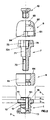
- the anchoring device of the invention has the first screw 1 with the shank 11 provided with outer threading (12) intended to be screwed into the spongy part 2 of the palatal bone and on the inside connected with the threaded blind hole 15, made to hold the threaded end of the second screw 7.
- Said first screw also has the substantially cylindrical collar 13, with a larger diameter than that of the screw shank and depth no greater than the cortical part 3 of said bone.
- Said collar is topped by head 14, preferably with a hexagonal profile and in any case not cylindrical, consenting the screwing maneuver of the first screw by means of a suitable instrument, and the lodging of the distance sleeve 6.
- Head 14 presents its upper surface 141 (fig. 2) which is substantially at the same level or emerges only slightly from the surface joining periost 4 and gum 5.
- a satisfactory variation in execution represented in fig. 5 has collar 13 with the lower basis surface provided with roughness 131 obtained by means of well-known techniques contributing, by biting into the cortical part of the bone (fig. 2), to increase resistance of screw 1 by increasing the surface in direct contact with the bone.
- the anchoring device also includes the distance sleeve 6 (figs. 1, 2, 6 and 7), with a substantially cylindrical outer surface 61 of a depth at least equal to the thickness of the gum 5 (fig. 1), and this sleeve presents on its inner surface two main hollows 62 and 63 that are mutually coaxial.
- the first hollow 62 non-cylindrical, has a profile such as to consent mating with head 14 of the first screw 1 (fig. 1) thus preventing its rotation with respect to the screw itself.
- the second hollow 63 is contiguous to the first and has a substantially cylindrical profile since it is suitable to receive the cylindrical shank of the screw 7 in its non-threaded middle part 71, when the threaded end 72 of said second screw is fully screwed into hole 15 of the first screw 1 (fig. 1).
- the depth of the non-threaded part 71 of the shank of this second screw is such that when it is fully embedded in the first screw, with distance sleeve 6 between them, it leaves between the upper rim 64 of the distance sleeve and the lower basis surface of the head 731 sufficient space to lodge at least one wire 9 (fig. 1).
- Said wire can be of the type with pre-formed slot to hook on to the shank of the second screw just below its head, or of the straight type passing laterally to the shank.
- cap 8 (figs. 1, 2, 10, 11) presenting a hollow formed by a first cylindrical part 81 (figs. 2, 11) and a second part 82 with a profile suitable to mate with head 73 of the second screw 7 thus preventing rotation of the cap with respect to the head itself.
- said cap presents at the top a central hole 83 for the passage of screw 10 blocking the cap to head 73 of the second screw.
- This maneuver also consents tightening wire 9 between the upper rim 64 of the distance sleeve 6 and the lower surface 731 of the head of the second screw 7 (fig. 1).
- the outlet of wire 9 from the cap face is consented by the presence in the face itself of at least two hollows 84 (figs. 2, 10, 11) that are either diametrically opposed or adjacent.
- the wire anchoring device 9 composed of all of its elements ensures secure stability, since it fully exploits the anchoring action particularly in the cortical part 3 of the bone.
- the gum 5 can grow back and definitively cover the head of the screw itself eliminating the need for a subsequent operation for the removal of the fastening element which is always required with the known devices with possible application of fillings to close the hole left by the screw.
- the blocking device of the invention attains all the required purposes. While in a phase of execution the material, usually titanium, the shapes and dimensions of the component elements of the device itself, can vary according to construction requirements and to the different structure of the mouth in which the device is to be applied.
Landscapes
- Health & Medical Sciences (AREA)
- Animal Behavior & Ethology (AREA)
- Orthopedic Medicine & Surgery (AREA)
- Dentistry (AREA)
- Epidemiology (AREA)
- Life Sciences & Earth Sciences (AREA)
- Oral & Maxillofacial Surgery (AREA)
- General Health & Medical Sciences (AREA)
- Public Health (AREA)
- Veterinary Medicine (AREA)
- Dental Tools And Instruments Or Auxiliary Dental Instruments (AREA)
- Surgical Instruments (AREA)
- Orthopedics, Nursing, And Contraception (AREA)
Applications Claiming Priority (2)
| Application Number | Priority Date | Filing Date | Title |
|---|---|---|---|
| IT98VI000181A ITVI980181A1 (it) | 1998-09-25 | 1998-09-25 | Dispositivo di ancoraggio per apparecchi adatti ai trattamenti di correzione ortodontica. |
| ITVI980181 | 1998-09-25 |
Publications (3)
| Publication Number | Publication Date |
|---|---|
| EP0988836A2 true EP0988836A2 (fr) | 2000-03-29 |
| EP0988836A3 EP0988836A3 (fr) | 2001-01-10 |
| EP0988836B1 EP0988836B1 (fr) | 2003-04-02 |
Family
ID=11426808
Family Applications (1)
| Application Number | Title | Priority Date | Filing Date |
|---|---|---|---|
| EP99118088A Expired - Lifetime EP0988836B1 (fr) | 1998-09-25 | 1999-09-24 | Dispositif d'ancrage pour des instruments orthodontiques |
Country Status (6)
| Country | Link |
|---|---|
| US (1) | US6155829A (fr) |
| EP (1) | EP0988836B1 (fr) |
| AT (1) | ATE235860T1 (fr) |
| DE (1) | DE69906442T2 (fr) |
| ES (1) | ES2196690T3 (fr) |
| IT (1) | ITVI980181A1 (fr) |
Cited By (3)
| Publication number | Priority date | Publication date | Assignee | Title |
|---|---|---|---|---|
| EP1212985A2 (fr) * | 2000-12-11 | 2002-06-12 | Arturo Hruska | Butée de cicatrisation permettant l'immobilisation d'implants dentaires et une sollicitation immédiate |
| WO2003009770A1 (fr) * | 2001-07-05 | 2003-02-06 | Altatec Medizintechnische Elemente Gmbh & Co. Kg | Systeme d'implant orthodontique de mobilisation dentaire |
| CN107362454A (zh) * | 2016-11-14 | 2017-11-21 | 周林 | 一种频谱治疗仪框架及频谱治疗仪 |
Families Citing this family (6)
| Publication number | Priority date | Publication date | Assignee | Title |
|---|---|---|---|---|
| ATE274850T1 (de) * | 2000-02-29 | 2004-09-15 | Synthes Ag | Endo-distraktor |
| DE102007058108A1 (de) * | 2007-12-03 | 2009-06-04 | Mondeal Medical Systems Gmbh | Verankerungsvorrichtung für die Zahn- und/oder Kieferregulierung |
| US20090176190A1 (en) * | 2008-01-07 | 2009-07-09 | Ormco Corporation | Screw anchored orthodontic appliance and methods |
| WO2009097386A1 (fr) * | 2008-02-01 | 2009-08-06 | Synthes Usa, Llc | Plaque d'ancrage d'os orthodontique avec tampon à mailles |
| US10743966B2 (en) * | 2015-01-21 | 2020-08-18 | Kwang Seob Kim | Implant unit |
| KR101849950B1 (ko) * | 2017-12-27 | 2018-04-20 | (주)에스겔 | 치과용 임플란트 |
Family Cites Families (5)
| Publication number | Priority date | Publication date | Assignee | Title |
|---|---|---|---|---|
| US5769630A (en) * | 1991-02-25 | 1998-06-23 | Louisiana State University, | Subperiosteal bone anchor |
| US5820369A (en) * | 1991-02-25 | 1998-10-13 | Nobel Biocare Ab | Subperiosteal bone anchor |
| US5066224A (en) * | 1991-02-25 | 1991-11-19 | Oasis Implants Incorporated | Orthodontic anchor |
| US5482463A (en) * | 1994-04-08 | 1996-01-09 | Wilson, Jr.; Richard S. | Anti-slippage mechanism for dental implant components |
| IL115661A (en) * | 1994-10-21 | 1999-11-30 | Straumann Inst Ag | Oral implant |
-
1998
- 1998-09-25 IT IT98VI000181A patent/ITVI980181A1/it unknown
-
1999
- 1999-09-24 DE DE69906442T patent/DE69906442T2/de not_active Expired - Fee Related
- 1999-09-24 ES ES99118088T patent/ES2196690T3/es not_active Expired - Lifetime
- 1999-09-24 EP EP99118088A patent/EP0988836B1/fr not_active Expired - Lifetime
- 1999-09-24 AT AT99118088T patent/ATE235860T1/de not_active IP Right Cessation
- 1999-09-27 US US09/406,145 patent/US6155829A/en not_active Expired - Fee Related
Non-Patent Citations (1)
| Title |
|---|
| None |
Cited By (5)
| Publication number | Priority date | Publication date | Assignee | Title |
|---|---|---|---|---|
| EP1212985A2 (fr) * | 2000-12-11 | 2002-06-12 | Arturo Hruska | Butée de cicatrisation permettant l'immobilisation d'implants dentaires et une sollicitation immédiate |
| EP1212985A3 (fr) * | 2000-12-11 | 2003-02-12 | Arturo Hruska | Butée de cicatrisation permettant l'immobilisation d'implants dentaires et une sollicitation immédiate |
| US6749430B2 (en) | 2000-12-11 | 2004-06-15 | Hruska Arturo | Healing post for intrasurgical immobilization of dental implants for immediate loading |
| WO2003009770A1 (fr) * | 2001-07-05 | 2003-02-06 | Altatec Medizintechnische Elemente Gmbh & Co. Kg | Systeme d'implant orthodontique de mobilisation dentaire |
| CN107362454A (zh) * | 2016-11-14 | 2017-11-21 | 周林 | 一种频谱治疗仪框架及频谱治疗仪 |
Also Published As
| Publication number | Publication date |
|---|---|
| US6155829A (en) | 2000-12-05 |
| EP0988836B1 (fr) | 2003-04-02 |
| DE69906442T2 (de) | 2004-04-08 |
| ITVI980181A1 (it) | 2000-03-25 |
| EP0988836A3 (fr) | 2001-01-10 |
| DE69906442D1 (de) | 2003-05-08 |
| ATE235860T1 (de) | 2003-04-15 |
| ES2196690T3 (es) | 2003-12-16 |
Similar Documents
| Publication | Publication Date | Title |
|---|---|---|
| US7806686B2 (en) | Anchor apparatus and method for orthodontic appliances | |
| EP2799031B1 (fr) | Implant dentaire de condensation de l'os | |
| EP0263274B2 (fr) | Prothèse filetée totalement implantée | |
| CA1311948C (fr) | Implant dentaire a vis | |
| AU609743B2 (en) | Dental prostheses | |
| USRE35784E (en) | Submergible screw-type dental implant and method of utilization | |
| US4416629A (en) | Osseointerfaced implanted artificial tooth | |
| US8029285B2 (en) | Implant, arrangement comprising an implant, and method for inserting said implant in bone tissue | |
| KR101240116B1 (ko) | 덴탈 임플란트 | |
| EP2145600A1 (fr) | Appareil amélioré d'implants dentaires en deux parties | |
| US20060216673A1 (en) | Dental implant | |
| AU6039398A (en) | Improved dental and orthopedic implant system | |
| US4661066A (en) | Movable plate implant | |
| US5752830A (en) | Removable dental implant | |
| HU201664B (en) | Enossal implant | |
| US4600388A (en) | Osseous integrated submergible implant | |
| EP0988836B1 (fr) | Dispositif d'ancrage pour des instruments orthodontiques | |
| EP1942826A1 (fr) | Implant de molaire et procede | |
| US20130045462A1 (en) | Dental implant fixing system | |
| KR101087921B1 (ko) | 치과용 임플란트 | |
| US20200330192A1 (en) | Dental implant with partial transmucosal penetration, and prosthetic assembly comprising such an implant | |
| JPH11151253A (ja) | 義歯を人間の顎に保持するための歯科医術用上部構造のための顎インプラント | |
| ZA200606187B (en) | Anchoring element for use in bone | |
| JP4404503B2 (ja) | 人工歯根 | |
| WO2009007401A2 (fr) | Pilier de cicatrisation, vis et procédé |
Legal Events
| Date | Code | Title | Description |
|---|---|---|---|
| PUAI | Public reference made under article 153(3) epc to a published international application that has entered the european phase |
Free format text: ORIGINAL CODE: 0009012 |
|
| AK | Designated contracting states |
Kind code of ref document: A2 Designated state(s): AT BE CH CY DE DK ES FI FR GB GR IE IT LI LU MC NL PT SE |
|
| AX | Request for extension of the european patent |
Free format text: AL;LT;LV;MK;RO;SI |
|
| PUAL | Search report despatched |
Free format text: ORIGINAL CODE: 0009013 |
|
| AK | Designated contracting states |
Kind code of ref document: A3 Designated state(s): AT BE CH CY DE DK ES FI FR GB GR IE IT LI LU MC NL PT SE |
|
| AX | Request for extension of the european patent |
Free format text: AL;LT;LV;MK;RO;SI |
|
| 17P | Request for examination filed |
Effective date: 20010709 |
|
| AKX | Designation fees paid |
Free format text: AT BE CH CY DE DK ES FI FR GB GR IE IT LI LU MC NL PT SE |
|
| RAP1 | Party data changed (applicant data changed or rights of an application transferred) |
Owner name: MAINO, BORTOLO GIULIANO |
|
| RIN1 | Information on inventor provided before grant (corrected) |
Inventor name: MAINO, BORTOLO GIULIANO |
|
| GRAH | Despatch of communication of intention to grant a patent |
Free format text: ORIGINAL CODE: EPIDOS IGRA |
|
| GRAH | Despatch of communication of intention to grant a patent |
Free format text: ORIGINAL CODE: EPIDOS IGRA |
|
| GRAA | (expected) grant |
Free format text: ORIGINAL CODE: 0009210 |
|
| AK | Designated contracting states |
Designated state(s): AT BE CH CY DE DK ES FI FR GB GR IE IT LI LU MC NL PT SE |
|
| PG25 | Lapsed in a contracting state [announced via postgrant information from national office to epo] |
Ref country code: NL Free format text: LAPSE BECAUSE OF FAILURE TO SUBMIT A TRANSLATION OF THE DESCRIPTION OR TO PAY THE FEE WITHIN THE PRESCRIBED TIME-LIMIT Effective date: 20030402 Ref country code: LI Free format text: LAPSE BECAUSE OF FAILURE TO SUBMIT A TRANSLATION OF THE DESCRIPTION OR TO PAY THE FEE WITHIN THE PRESCRIBED TIME-LIMIT Effective date: 20030402 Ref country code: FR Free format text: LAPSE BECAUSE OF FAILURE TO SUBMIT A TRANSLATION OF THE DESCRIPTION OR TO PAY THE FEE WITHIN THE PRESCRIBED TIME-LIMIT Effective date: 20030402 Ref country code: FI Free format text: LAPSE BECAUSE OF FAILURE TO SUBMIT A TRANSLATION OF THE DESCRIPTION OR TO PAY THE FEE WITHIN THE PRESCRIBED TIME-LIMIT Effective date: 20030402 Ref country code: CH Free format text: LAPSE BECAUSE OF FAILURE TO SUBMIT A TRANSLATION OF THE DESCRIPTION OR TO PAY THE FEE WITHIN THE PRESCRIBED TIME-LIMIT Effective date: 20030402 Ref country code: BE Free format text: LAPSE BECAUSE OF FAILURE TO SUBMIT A TRANSLATION OF THE DESCRIPTION OR TO PAY THE FEE WITHIN THE PRESCRIBED TIME-LIMIT Effective date: 20030402 Ref country code: AT Free format text: LAPSE BECAUSE OF FAILURE TO SUBMIT A TRANSLATION OF THE DESCRIPTION OR TO PAY THE FEE WITHIN THE PRESCRIBED TIME-LIMIT Effective date: 20030402 |
|
| REG | Reference to a national code |
Ref country code: GB Ref legal event code: FG4D |
|
| REG | Reference to a national code |
Ref country code: CH Ref legal event code: EP |
|
| REG | Reference to a national code |
Ref country code: IE Ref legal event code: FG4D |
|
| REF | Corresponds to: |
Ref document number: 69906442 Country of ref document: DE Date of ref document: 20030508 Kind code of ref document: P |
|
| PG25 | Lapsed in a contracting state [announced via postgrant information from national office to epo] |
Ref country code: SE Free format text: LAPSE BECAUSE OF FAILURE TO SUBMIT A TRANSLATION OF THE DESCRIPTION OR TO PAY THE FEE WITHIN THE PRESCRIBED TIME-LIMIT Effective date: 20030702 Ref country code: PT Free format text: LAPSE BECAUSE OF FAILURE TO SUBMIT A TRANSLATION OF THE DESCRIPTION OR TO PAY THE FEE WITHIN THE PRESCRIBED TIME-LIMIT Effective date: 20030702 Ref country code: GR Free format text: LAPSE BECAUSE OF FAILURE TO SUBMIT A TRANSLATION OF THE DESCRIPTION OR TO PAY THE FEE WITHIN THE PRESCRIBED TIME-LIMIT Effective date: 20030702 Ref country code: DK Free format text: LAPSE BECAUSE OF FAILURE TO SUBMIT A TRANSLATION OF THE DESCRIPTION OR TO PAY THE FEE WITHIN THE PRESCRIBED TIME-LIMIT Effective date: 20030702 |
|
| NLV1 | Nl: lapsed or annulled due to failure to fulfill the requirements of art. 29p and 29m of the patents act | ||
| PG25 | Lapsed in a contracting state [announced via postgrant information from national office to epo] |
Ref country code: LU Free format text: LAPSE BECAUSE OF NON-PAYMENT OF DUE FEES Effective date: 20030924 Ref country code: IE Free format text: LAPSE BECAUSE OF NON-PAYMENT OF DUE FEES Effective date: 20030924 Ref country code: GB Free format text: LAPSE BECAUSE OF NON-PAYMENT OF DUE FEES Effective date: 20030924 Ref country code: CY Free format text: LAPSE BECAUSE OF FAILURE TO SUBMIT A TRANSLATION OF THE DESCRIPTION OR TO PAY THE FEE WITHIN THE PRESCRIBED TIME-LIMIT Effective date: 20030924 |
|
| PG25 | Lapsed in a contracting state [announced via postgrant information from national office to epo] |
Ref country code: MC Free format text: LAPSE BECAUSE OF NON-PAYMENT OF DUE FEES Effective date: 20030930 |
|
| REG | Reference to a national code |
Ref country code: CH Ref legal event code: PL |
|
| REG | Reference to a national code |
Ref country code: ES Ref legal event code: FG2A Ref document number: 2196690 Country of ref document: ES Kind code of ref document: T3 |
|
| PLBE | No opposition filed within time limit |
Free format text: ORIGINAL CODE: 0009261 |
|
| STAA | Information on the status of an ep patent application or granted ep patent |
Free format text: STATUS: NO OPPOSITION FILED WITHIN TIME LIMIT |
|
| EN | Fr: translation not filed | ||
| 26N | No opposition filed |
Effective date: 20040105 |
|
| GBPC | Gb: european patent ceased through non-payment of renewal fee |
Effective date: 20030924 |
|
| REG | Reference to a national code |
Ref country code: IE Ref legal event code: MM4A |
|
| PGFP | Annual fee paid to national office [announced via postgrant information from national office to epo] |
Ref country code: DE Payment date: 20040930 Year of fee payment: 6 |
|
| PGFP | Annual fee paid to national office [announced via postgrant information from national office to epo] |
Ref country code: ES Payment date: 20041028 Year of fee payment: 6 |
|
| PG25 | Lapsed in a contracting state [announced via postgrant information from national office to epo] |
Ref country code: ES Free format text: LAPSE BECAUSE OF NON-PAYMENT OF DUE FEES Effective date: 20050926 |
|
| PG25 | Lapsed in a contracting state [announced via postgrant information from national office to epo] |
Ref country code: DE Free format text: LAPSE BECAUSE OF NON-PAYMENT OF DUE FEES Effective date: 20060401 |
|
| PGFP | Annual fee paid to national office [announced via postgrant information from national office to epo] |
Ref country code: IT Payment date: 20060930 Year of fee payment: 8 |
|
| REG | Reference to a national code |
Ref country code: ES Ref legal event code: FD2A Effective date: 20050926 |
|
| PG25 | Lapsed in a contracting state [announced via postgrant information from national office to epo] |
Ref country code: IT Free format text: LAPSE BECAUSE OF NON-PAYMENT OF DUE FEES Effective date: 20070924 |