EP0987518A2 - Faseroptischer Kreisel mit geschlossener Regelschleife und Kompensation des Shupe-Effekts - Google Patents
Faseroptischer Kreisel mit geschlossener Regelschleife und Kompensation des Shupe-Effekts Download PDFInfo
- Publication number
- EP0987518A2 EP0987518A2 EP99118412A EP99118412A EP0987518A2 EP 0987518 A2 EP0987518 A2 EP 0987518A2 EP 99118412 A EP99118412 A EP 99118412A EP 99118412 A EP99118412 A EP 99118412A EP 0987518 A2 EP0987518 A2 EP 0987518A2
- Authority
- EP
- European Patent Office
- Prior art keywords
- fiber
- temperature
- drift
- optic gyroscope
- output signal
- Prior art date
- Legal status (The legal status is an assumption and is not a legal conclusion. Google has not performed a legal analysis and makes no representation as to the accuracy of the status listed.)
- Granted
Links
Images
Classifications
-
- G—PHYSICS
- G01—MEASURING; TESTING
- G01C—MEASURING DISTANCES, LEVELS OR BEARINGS; SURVEYING; NAVIGATION; GYROSCOPIC INSTRUMENTS; PHOTOGRAMMETRY OR VIDEOGRAMMETRY
- G01C19/00—Gyroscopes; Turn-sensitive devices using vibrating masses; Turn-sensitive devices without moving masses; Measuring angular rate using gyroscopic effects
- G01C19/58—Turn-sensitive devices without moving masses
- G01C19/64—Gyrometers using the Sagnac effect, i.e. rotation-induced shifts between counter-rotating electromagnetic beams
- G01C19/72—Gyrometers using the Sagnac effect, i.e. rotation-induced shifts between counter-rotating electromagnetic beams with counter-rotating light beams in a passive ring, e.g. fibre laser gyrometers
Definitions
- the invention relates to a method for compensation of temperature-related Drift changes in a fiber optic gyroscope and on one fiber optic gyroscope that works according to the method.
- two light beams originating from a light source are radiated into a fiber coil in opposite directions in order to pass through the same in opposite directions. After the light rays have passed through the coil, they are combined again to produce an interference image on a detector. If the coil is rotated about its axis, the Sagnac effect creates a non-reciprocal phase shift between the two oppositely irradiated light beams, which produces a shift in the interference pattern. The magnitude and direction of the interference shift is proportional to the rate and direction of rotation of the coil around its axis.
- the detector output is processed through electronic control loops to a non-reciprocal phase shift that applies a phase modulator, which is generally located at one end of the fiber coil, to compensate for the Sagnac phase shift of the two opposite light waves generated by the rotation.
- the scale factor S depends on changes in the fiber length of the coil. From EP 0 245 118 B1 it is known to stabilize the scale factor S by measuring and correcting the fiber length in a fiber optic gyroscope.
- ⁇ is the transit time of the light through the coil
- c the speed of light
- n the refractive index of the fiber
- L the length of the fiber on the coil.
- f M a measure of the optical fiber length on the spool. If the refractive index n is constant, the regulated modulation frequency - as is known per se - can be used to correct the scale factor, as a result of which high intensity jumps at the detector are avoided. If, on the other hand, the refractive index n changes, this scale factor correction cannot be used because f M depends on it, but the scale factor S does not.
- the Shupe effect can be achieved by a so-called quadropole winding of the coil to reduce.
- a temperature model that depends on the Temperature T and its time derivatives T ⁇ and T ⁇ is complicated and not linear.
- the repeatability and long-term stability is mainly because of this bad, because there are internal pressure differences, especially in the organic ones used Be able to compensate for materials in the long term.
- Temperature sensors are not placed in the fiber winding of the coils. Because of the poor heat conduction of fiber spools, the temperature measurements represent usually not good the temperature of the coil winding.
- Such Temperature models to limit the Shupe effect are known, but complete there are no satisfactory solutions.
- the invention is therefore based on the object of a method for compensation of temperature-related drift changes in a fiber optic Specify gyro and a gyro working according to this method by that the Shupe effect with its influence on the drift of a fiber circle compensates.
- the invention is based on the knowledge that the direct influencing variable on the Shupe effect is the change in the optical path n ⁇ L, where n is the refractive index of the optical fiber and L is its length, the spatial differences of which have an effect on asymmetries of the winding. Therefore, according to the invention, a model for compensating the Shupe effect is derived from the measurement of the optical path n ⁇ L and the drift change in the output signal of the fiber optic gyroscope is compensated for on the basis of the model formed. As shown above, f M is a direct measure of n ⁇ L.
- a fiber optic gyroscope operating according to the method according to the invention is defined in claim 9.
- An advantageous development is the subject of claim 10.
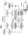
- FIG. 1 is a block diagram of an embodiment of a fiber optic gyroscope with a closed control loop that corresponds to this Invention is constructed.
- FIG. 1 illustrates the structure of a fiber optic gyroscope with closed control loop, with regard to the actual interferometer only a minimal configuration is shown.
- a light source 1 for example a superluminescent diode, belongs to this interferometer (SLD), whose light beam via a first coupler 2 via a Polarizer 3 reaches a second coupler 4 and in the latter in a Clockwise and in a counter-clockwise partial light beam is divided.
- SLD interferometer
- the two partial light beams are after passing through the Coil 5 reunited on the second coupler 4 and pass through the first Coupler 2 in a known manner on a photodetector 7, the one of the intensity the result of the superposition of the two reunited partial light beams corresponding signal via an amplifier 9 to one described below provides electronic signal processing circuit.
- the idle state of the Gyro i.e. without rotation of the coil 5
- Axis occurs between the two light beams due to the Sagnac effect non-reciprocal phase shift, whereby the detected at the detector 7 Intensity varies.
- a modulation generator 8 is applied via a controllable amplifier 15 and the phase modulator 6 in turn via a VCO described below - i.e. a voltage-controlled one Control loop - excited, z.
- a detector 16 for optical length include a regulator 17 and a voltage controlled oscillator 18. The switchover the excitation of the phase modulator 6 takes place synchronously with the throughput time of light through the coil 5.
- the output signal of the photodetector 7 passes through the amplifier 9 together with the reference of the modulation generator 8 to a synchronous demodulator 10, which demodulates the detector signal.
- the synchronous demodulator 10 supplies the direction of the phase shift at the detector 7 signal, which is integrated by a controller 11 and is applied to a ramp generator 12, which in turn is the phase modulator 6 so acted that a non-reciprocal phase shift between the two partial light rays passing through the coil 5 are generated, so that compensated for the phase shift generated by rotation of the coil 5 becomes.
- the detector 7 should be switched on due to Characteristic curve no signal arise.
- the output signal the amplifier 9 also acts on the detector 16 for optical length, which additionally with which the synchronization with the passage time of the light through the coil 5 generating input signal of the modulation generator 8 with Reference "b" is fed.
- the optical length detector 16 produces an output voltage which on the one hand depends on whether the transitions in the intensity signal of the detector 7 too early or too late with regard to the phase switching take place and which also depends on the duration of the transition pulses.
- the output signals of the optical length detector 16 are represented by a Controller 17 amplified, the output signal of a voltage controllable Oscillator 18 excited, which thus feeds and synchronizes the modulation generator 8.
- the output signal of a ramp generator 12 is sent to a microprocessor 19 placed the corrected amplitude and direction of the coil 5 acting rotation determines and outputs.
- the fiber optic gyroscope described so far differs in terms of of the described in the cited document EP 0 245 118 B1 u. a. in this, that the frequency of the voltage controlled oscillator 18 is not for scale factor correction because of the dependence on the refractive index n is used. Rather, the microprocessor 19 is at another input by the output signal of the voltage controlled oscillator 18 applied to the to compensate for the Shupe effect explained above.
- Designated assembly 20 is a model of the drift due to the Shupe effect of the respective fiber optic gyroscope saved.
- This drift model depends on the optical path n ⁇ L of the light path through the fiber coil 5.
- the microprocessor 19 corrects the calculated result of the amplitude and direction of the rotation of the fiber coil 5.
- the correction of the optical light wavelength is carried out the modulation frequency f M of the VCO of the control circuit 16, 17, 18 is obtained.
- the model of the temperature-dependent drift can, for example, be dependent on the modulation frequency f M , but is mainly dependent on its first time derivative f ⁇ M or its second time derivative f ⁇ M.
- the model is obtained, for example, by recording the time profile of the modulation frequency and its time derivatives of temperature and the time profile of the temperature-dependent drift for the gyro.
- This, for example, experimentally determined model of the temperature-dependent drift corresponds, for example, to a higher order polynomial, in individual cases a linear function, for example of f M.
- the Shupe effect compensation 20 can either be a computing module that calculates a compensation value depending on the applied modulation frequency f M , or can be constructed as a look-up table from which an assigned compensation value is read out according to the applied modulation frequency f M.
- the compensation value can either be chosen so that it is for correction the output signal of the microprocessor 19 simply to its previously calculated Result is added, so its output signal is applied directly. However, the compensation value can also be chosen so that it is in suitable form in the calculation of the amount carried out in the microprocessor 19 and the direction of rotation acting on the spool.
Landscapes
- Physics & Mathematics (AREA)
- Engineering & Computer Science (AREA)
- Optics & Photonics (AREA)
- Electromagnetism (AREA)
- Power Engineering (AREA)
- General Physics & Mathematics (AREA)
- Radar, Positioning & Navigation (AREA)
- Remote Sensing (AREA)
- Gyroscopes (AREA)
Abstract
Description
- die Ausdehnungskoeffizienten des Hüll- und Kernmaterials der optischen Faser, der Beschichtung, der Klebeschichten und des Spulenkörpers;
- die Variation des Brechungsindexes über der Temperatur; und
- die Veränderung des internen Drucks in der Spule, der durch unterschiedliche Ausdehnungskoeffizienten der oben genannten Materialien erzeugt wird, und der durch seinen Einfluß wiederum auf den Brechungsindex sowie auf die Längendehnung wirkt.
Claims (10)
- Verfahren zur Kompensation von temperaturbedingten Driftänderungen in einem faseroptischen Kreisel, gekennzeichnet durch folgende Schritte:Messung des optischen Wegs (n·L) des Lichts durch eine Faserspule:Berechnen der temperaturabhängigen zeitlichen Änderung des optischen Wegs (n·L) des Lichts durch eine Faserspule (5) des faseroptischen Kreisels; undKompensation dieser Driftänderungen im Ausgangssignal des faseroptischen Kreisels auf der Grundlage eines die zeitliche Änderung des optischen Wegs (n·L) nachbildenden Modells.
- Verfahren nach Anspruch 1, dadurch gekennzeichnet, daß der optische Weg (n·L) des Lichts durch eine über einen VCO-Regelkreis (16, 17, 18) erzeugte Modulationsfrequenz (fM) gemessen wird.
- Verfahren nach Anspruch 2, dadurch gekennzeichnet, daß das Modell der temperaturbedingten Drift abhängig von der Modulationsfrequenz (fM), deren erster zeitlicher Ableitung (f ˙M) und/oder von deren zweiter zeitlicher Ableitung (f ¨M) gewonnen wird.
- Verfahren nach nach Anspruch 2 oder 3, dadurch gekennzeichnet, daß das Modell der temperaturbedingten Drift empirisch generiert wird, indem für den faseroptischen Kreisel der zeitliche Verlauf der Modulationsfrequenz und deren zeitlicher Ableitungen abhängig von der Temperatur (fM(T); f ˙M(T); (f ¨M)T)) und der zeitliche Verlauf der temperaturabhängigen Drift erfaßt werden.
- Verfahren nach einem der vorstehenden Ansprüche, dadurch gekennzeichnet, daß das Modell der temperaturbedingten Drift über einen Polynomansatz gewonnen wird.
- Verfahren nach einem der vorstehenden Ansprüche 1 bis 4, dadurch gekennzeichnet, daß ein lineares Modell der temperaturbedingten Drift erzeugt wird.
- Verfahren nach einem der vorstehenden Ansprüche, dadurch gekennzeichnet, daß zur Kompensation der Driftänderungen in einem Ausgangssignal des faseroptischen Kreisels jeweils auf Grundlage des gebildeten Modells ein Kompensationswert errechnet wird, mit dem das Ausgangssignal beaufschlagt wird.
- Verfahren nach einem der vorstehenden Ansprüche, dadurch gekennzeichnet, daß zur Kompensation der Driftänderungen in einem Ausgangssignal des faseroptischen Kreisels jeweils ein auf Grundlage des gebildeten Modells berechneter Kompensationswert aus einem Speicher ausgelesen wird, der das Ausgangssignal beeinflußt.
- Interferometrischer faseroptischer Kreisel, mit:einer zu einer Spule (5) gewickelten optischen Faser mit einer Länge (L),einer Lichtquelle (1), deren Lichtstrahl in einem Koppler (4) in wenigstens zwei Teilstrahlen aufgeteilt wird, die in Gegenrichtung durch die Faser laufen,einem Mittel (4) zur Wiedervereinigung der Teilstrahlen, um ein Interferenzbild der beiden wiedervereinigten Teilstrahlen zu bilden, nachdem die Teilstrahlen die optische Faser verlassen haben.einem vom Interferenzbild beaufschlagten Detektor (7) zur Erzeugung eines Signals, das die Intensität des Interferenzbildes anzeigt,einem Auswerteeinheit (19), die die auf die Faserspule (5) wirkende Drehung abhängig von dem Ausgangssignal des Detektors (7) bestimmt, gekennzeichnet durcheine Einrichtung zur Kompensation von temperaturabhängigen Driftänderingen des Kreisels abhängig von der Änderung der optischen Länge (n·L) der Faser (5).
- Kreisel nach Anspruch 9, dadurch gekennzeichnet, daßdie Einrichtung zur Kompensation der temperaturabhängigen Änderungen der optischen Länge (n·L) der Faserspule (5) einen VCO-Regelkreis (16, 17, 18) enthält, und daßin Abhängigkeit vom Ausgangssignal dieses VCO-Regelkreises (16, 17, 18) Korrekturwerte für die Auswerteeinheit (19) unter Rückgriff auf ein gespeichertes Modell der temperaturabhängigen Driftänderungen des Kreisels erzeugbar sind.
Applications Claiming Priority (2)
| Application Number | Priority Date | Filing Date | Title |
|---|---|---|---|
| DE19842702 | 1998-09-17 | ||
| DE19842702A DE19842702C1 (de) | 1998-09-17 | 1998-09-17 | Faseroptischer Kreisel mit geschlossener Regelschleife und Kompensation des Shupe-Effekts |
Publications (3)
| Publication Number | Publication Date |
|---|---|
| EP0987518A2 true EP0987518A2 (de) | 2000-03-22 |
| EP0987518A3 EP0987518A3 (de) | 2003-01-08 |
| EP0987518B1 EP0987518B1 (de) | 2009-02-18 |
Family
ID=7881341
Family Applications (1)
| Application Number | Title | Priority Date | Filing Date |
|---|---|---|---|
| EP99118412A Expired - Lifetime EP0987518B1 (de) | 1998-09-17 | 1999-09-16 | Faseroptischer Kreisel mit geschlossener Regelschleife und Kompensation des Shupe-Effekts |
Country Status (3)
| Country | Link |
|---|---|
| US (1) | US6181428B1 (de) |
| EP (1) | EP0987518B1 (de) |
| DE (1) | DE19842702C1 (de) |
Cited By (7)
| Publication number | Priority date | Publication date | Assignee | Title |
|---|---|---|---|---|
| WO2010022822A1 (de) * | 2008-08-28 | 2010-03-04 | Northrop Grumman Litef Gmbh | FASEROPTISCHES INTERFEROMETER UND VERFAHREN ZUR BESTIMMUNG PHYSIKALISCHER ZUSTANDSGRÖßEN IM INNERN EINER FASERSPULE EINES FASEROPTISCHEN INTERFEROMETERS |
| CN102650527A (zh) * | 2012-05-25 | 2012-08-29 | 北京航空航天大学 | 一种基于时间序列分析消噪的光纤陀螺温度补偿方法 |
| CN103593538A (zh) * | 2013-11-28 | 2014-02-19 | 东南大学 | 一种遗传算法优化动态递归神经网络的光纤陀螺温度漂移建模方法 |
| CN103954300A (zh) * | 2014-04-30 | 2014-07-30 | 东南大学 | 基于优化ls-svm的光纤陀螺温度漂移误差补偿方法 |
| CN109556595A (zh) * | 2018-10-19 | 2019-04-02 | 上海新跃联汇电子科技有限公司 | 一种利用偏振分离消除热效应的光纤陀螺 |
| CN112729347A (zh) * | 2021-01-19 | 2021-04-30 | 湖北三江航天万峰科技发展有限公司 | 一种光纤陀螺温度补偿方法、装置、电子设备及存储介质 |
| CN116858209A (zh) * | 2023-07-10 | 2023-10-10 | 中国科学院苏州纳米技术与纳米仿生研究所 | 基于谐振腔实时温度检测控制的光学陀螺系统 |
Families Citing this family (9)
| Publication number | Priority date | Publication date | Assignee | Title |
|---|---|---|---|---|
| CN100368774C (zh) * | 2005-06-07 | 2008-02-13 | 中国航天时代电子公司 | 光纤陀螺惯测装置快速启动和精度保证的工程实现方法 |
| US8514401B2 (en) | 2010-07-16 | 2013-08-20 | Peking University | All-fiber interferometric fiber optic gyroscope having a minimum reciprocal configuration |
| CN107621269B (zh) * | 2016-07-15 | 2020-08-04 | 北京计算机技术及应用研究所 | 光纤陀螺温度漂移误差补偿方法 |
| CN106441369B (zh) * | 2016-10-31 | 2020-01-10 | 苏州光环科技有限公司 | 光纤环的测试系统 |
| RU171674U1 (ru) * | 2016-12-20 | 2017-06-09 | Федеральное государственное унитарное предприятие "Центральный научно-исследовательский институт машиностроения" (ФГУП ЦНИИмаш) | Система термостабилизации волоконного контура волоконно-оптического гироскопа космического аппарата |
| CN110132253A (zh) * | 2019-04-23 | 2019-08-16 | 浙江大学 | 一种激光驱动数字闭环去偏光纤陀螺及激光线宽展宽方法 |
| CN111964659B (zh) * | 2020-06-28 | 2022-12-09 | 北京航天时代光电科技有限公司 | 一种光纤陀螺光纤环温度测试与评价系统 |
| CN115371659B (zh) * | 2022-10-14 | 2023-02-24 | 武汉优米捷光电子制造有限责任公司 | 一种带前向校正的光纤陀螺全温零偏补偿方法 |
| CN115855016B (zh) * | 2023-02-27 | 2023-06-16 | 南开大学 | 一种光纤陀螺仪低温冲击误差补偿方法 |
Family Cites Families (8)
| Publication number | Priority date | Publication date | Assignee | Title |
|---|---|---|---|---|
| GB8611394D0 (en) * | 1986-05-08 | 1986-10-29 | British Aerospace | Fibre optic gyroscopes |
| US5212711A (en) * | 1992-02-18 | 1993-05-18 | At&T Bell Laboratories | Harmonically mode-locked laser |
| DE4301479A1 (de) * | 1993-01-21 | 1994-07-28 | Deutsche Aerospace | Verfahren und Vorrichtung zum Korrigieren der Meßsignale eines Faserkreisels |
| US5329349A (en) * | 1993-05-10 | 1994-07-12 | Litton Systems, Inc. | Method for tuning fiber optic sensor coils |
| US5416585A (en) * | 1994-05-19 | 1995-05-16 | Alliedsignal Inc. | Fiber optic gyro drift rate compenstion based on temperature |
| JP3234429B2 (ja) * | 1995-01-17 | 2001-12-04 | 日本電信電話株式会社 | モード同期レーザの動作安定化装置 |
| US5767509A (en) * | 1996-12-24 | 1998-06-16 | Litton Systems, Inc. | Fiber optic sensor coil including buffer regions |
| US6028668A (en) * | 1998-02-04 | 2000-02-22 | Rockwell Collins, Inc. | Fiber optic gyroscope having improved readout and modulation index control |
-
1998
- 1998-09-17 DE DE19842702A patent/DE19842702C1/de not_active Expired - Fee Related
-
1999
- 1999-09-15 US US09/396,230 patent/US6181428B1/en not_active Expired - Fee Related
- 1999-09-16 EP EP99118412A patent/EP0987518B1/de not_active Expired - Lifetime
Cited By (12)
| Publication number | Priority date | Publication date | Assignee | Title |
|---|---|---|---|---|
| WO2010022822A1 (de) * | 2008-08-28 | 2010-03-04 | Northrop Grumman Litef Gmbh | FASEROPTISCHES INTERFEROMETER UND VERFAHREN ZUR BESTIMMUNG PHYSIKALISCHER ZUSTANDSGRÖßEN IM INNERN EINER FASERSPULE EINES FASEROPTISCHEN INTERFEROMETERS |
| US8982356B2 (en) | 2008-08-28 | 2015-03-17 | Northrop Grumman Litef Gmbh | Fiber optic interferometer and method for determining physical state parameters in the interior of a fiber coil of a fiber optic interferometer |
| CN102650527A (zh) * | 2012-05-25 | 2012-08-29 | 北京航空航天大学 | 一种基于时间序列分析消噪的光纤陀螺温度补偿方法 |
| CN102650527B (zh) * | 2012-05-25 | 2014-12-03 | 北京航空航天大学 | 一种基于时间序列分析消噪的光纤陀螺温度补偿方法 |
| CN103593538A (zh) * | 2013-11-28 | 2014-02-19 | 东南大学 | 一种遗传算法优化动态递归神经网络的光纤陀螺温度漂移建模方法 |
| CN103593538B (zh) * | 2013-11-28 | 2017-03-22 | 东南大学 | 一种遗传算法优化动态递归神经网络的光纤陀螺温度漂移建模方法 |
| CN103954300A (zh) * | 2014-04-30 | 2014-07-30 | 东南大学 | 基于优化ls-svm的光纤陀螺温度漂移误差补偿方法 |
| CN109556595A (zh) * | 2018-10-19 | 2019-04-02 | 上海新跃联汇电子科技有限公司 | 一种利用偏振分离消除热效应的光纤陀螺 |
| CN109556595B (zh) * | 2018-10-19 | 2022-10-25 | 上海新跃联汇电子科技有限公司 | 一种利用偏振分离消除热效应的光纤陀螺 |
| CN112729347A (zh) * | 2021-01-19 | 2021-04-30 | 湖北三江航天万峰科技发展有限公司 | 一种光纤陀螺温度补偿方法、装置、电子设备及存储介质 |
| CN112729347B (zh) * | 2021-01-19 | 2022-03-29 | 湖北三江航天万峰科技发展有限公司 | 一种光纤陀螺温度补偿方法、装置、电子设备及存储介质 |
| CN116858209A (zh) * | 2023-07-10 | 2023-10-10 | 中国科学院苏州纳米技术与纳米仿生研究所 | 基于谐振腔实时温度检测控制的光学陀螺系统 |
Also Published As
| Publication number | Publication date |
|---|---|
| EP0987518B1 (de) | 2009-02-18 |
| DE19842702C1 (de) | 2000-03-30 |
| US6181428B1 (en) | 2001-01-30 |
| EP0987518A3 (de) | 2003-01-08 |
Similar Documents
| Publication | Publication Date | Title |
|---|---|---|
| DE19842702C1 (de) | Faseroptischer Kreisel mit geschlossener Regelschleife und Kompensation des Shupe-Effekts | |
| DE4039371C2 (de) | Einrichtung zur Stabilisierung der Wellenlänge einer Laserdiode | |
| DE4314486C2 (de) | Absolutinterferometrisches Meßverfahren sowie dafür geeignete Laserinterferometeranordnung | |
| DE69105162T2 (de) | Faseroptische Messeinrichtung, Gyrometer, Navigations- und Stabilisierungssystem, Stromsensor. | |
| EP2223038B1 (de) | Interferometeranordnung und verfahren zu deren betrieb | |
| DE69602623T2 (de) | Lichtquelle für faseroptischen kreisel mit wellenlängenregelung | |
| EP2778611B1 (de) | Unterdrückung des Lock-In-Effekts aufgrund eines MIOC-Frequenzgangs beim faseroptischen Sagnac-Interferometer | |
| DE69820259T2 (de) | Faseroptischer kreisel mit schwingungsfehlerkompensation | |
| EP0172390A2 (de) | Verfahren und Einrichtung zur Drehratenauslesung mittels eines passiven optischen Resonators | |
| EP0652417B1 (de) | Faseroptisches Sagnac-Interferometer zur Drehratenmessung mit wellenlängenstabilisierter Lichtquelle | |
| DE68916785T2 (de) | Gyroskop aus optischer faser mit geschlossener schleife. | |
| EP0254756B1 (de) | Verfahren zur Drehratenmessung mittels eines passiven optischen Resonators | |
| DE3040202A1 (de) | Ringlaser | |
| EP2318806B1 (de) | FASEROPTISCHES INTERFEROMETER UND VERFAHREN ZUR BESTIMMUNG PHYSIKALISCHER ZUSTANDSGRÖßEN IM INNERN EINER FASERSPULE EINES FASEROPTISCHEN INTERFEROMETERS | |
| DE69000146T2 (de) | Faseroptischer kreisel. | |
| DE19730522C1 (de) | Verfahren zur Erhöhung der Stabilität eines faseroptischen Kreises und damit stabilisierter faseroptischer Kreisel | |
| DE102015004039A1 (de) | Mittelwertfrei gesteuerter Phasenmodulator für faseroptische Kreisel und faseroptischer Kreisel | |
| DE69409103T2 (de) | Schnelleinschaltende quelle für faseroptischen kreisel | |
| EP3088844B1 (de) | Faseroptisches system und verfahren zur reduktion von biasfehlern in einem solchen faseroptischen system | |
| EP0436052B1 (de) | Faseroptisches Sagnac-Interferometer mit digitaler Phasenrampenrückstellung zur Drehratenmessung | |
| DE69312011T2 (de) | Drehratenmessvorrichtung | |
| DE69213477T2 (de) | Bestimmung der laufzeit des optischen signals in einem optischen interferometer | |
| EP1049911A1 (de) | Verfahren und einrichtung zur stabilisierung des skalenfaktors eines faseroptischen kreisels | |
| DE68903616T2 (de) | Fiberoptische messeinrichtung, gyrometer, navigations- und stabilisationssystem. | |
| EP0607526B1 (de) | Verfahren und Vorrichtung zum Korrigieren der Messsignale eines Faserkreisels |
Legal Events
| Date | Code | Title | Description |
|---|---|---|---|
| PUAI | Public reference made under article 153(3) epc to a published international application that has entered the european phase |
Free format text: ORIGINAL CODE: 0009012 |
|
| AK | Designated contracting states |
Kind code of ref document: A2 Designated state(s): AT BE CH CY DE DK ES FI FR GB GR IE IT LI LU MC NL PT SE |
|
| AX | Request for extension of the european patent |
Free format text: AL;LT;LV;MK;RO;SI |
|
| PUAL | Search report despatched |
Free format text: ORIGINAL CODE: 0009013 |
|
| AK | Designated contracting states |
Kind code of ref document: A3 Designated state(s): AT BE CH CY DE DK ES FI FR GB GR IE IT LI LU MC NL PT SE |
|
| AX | Request for extension of the european patent |
Free format text: AL;LT;LV;MK;RO;SI |
|
| RIC1 | Information provided on ipc code assigned before grant |
Free format text: 7G 01C 19/72 A, 7G 05D 23/19 B, 7H 01S 3/067 B |
|
| 17P | Request for examination filed |
Effective date: 20030508 |
|
| AKX | Designation fees paid |
Designated state(s): FR GB |
|
| REG | Reference to a national code |
Ref country code: DE Ref legal event code: 8566 |
|
| 17Q | First examination report despatched |
Effective date: 20070312 |
|
| GRAP | Despatch of communication of intention to grant a patent |
Free format text: ORIGINAL CODE: EPIDOSNIGR1 |
|
| GRAS | Grant fee paid |
Free format text: ORIGINAL CODE: EPIDOSNIGR3 |
|
| RAP1 | Party data changed (applicant data changed or rights of an application transferred) |
Owner name: NORTHROP GRUMMAN LITEF GMBH |
|
| GRAA | (expected) grant |
Free format text: ORIGINAL CODE: 0009210 |
|
| AK | Designated contracting states |
Kind code of ref document: B1 Designated state(s): FR GB |
|
| REG | Reference to a national code |
Ref country code: GB Ref legal event code: FG4D Free format text: NOT ENGLISH |
|
| PGFP | Annual fee paid to national office [announced via postgrant information from national office to epo] |
Ref country code: GB Payment date: 20090922 Year of fee payment: 11 |
|
| PLBE | No opposition filed within time limit |
Free format text: ORIGINAL CODE: 0009261 |
|
| STAA | Information on the status of an ep patent application or granted ep patent |
Free format text: STATUS: NO OPPOSITION FILED WITHIN TIME LIMIT |
|
| 26N | No opposition filed |
Effective date: 20091119 |
|
| GBPC | Gb: european patent ceased through non-payment of renewal fee |
Effective date: 20100916 |
|
| REG | Reference to a national code |
Ref country code: FR Ref legal event code: ST Effective date: 20110531 |
|
| PG25 | Lapsed in a contracting state [announced via postgrant information from national office to epo] |
Ref country code: FR Free format text: LAPSE BECAUSE OF NON-PAYMENT OF DUE FEES Effective date: 20100930 |
|
| PG25 | Lapsed in a contracting state [announced via postgrant information from national office to epo] |
Ref country code: GB Free format text: LAPSE BECAUSE OF NON-PAYMENT OF DUE FEES Effective date: 20100916 |
|
| PGFP | Annual fee paid to national office [announced via postgrant information from national office to epo] |
Ref country code: FR Payment date: 20091005 Year of fee payment: 11 |