EP0985205B1 - System zur überwachung von elektromagnetisch gesicherten artikeln in mehreren überwachungszonen - Google Patents
System zur überwachung von elektromagnetisch gesicherten artikeln in mehreren überwachungszonen Download PDFInfo
- Publication number
- EP0985205B1 EP0985205B1 EP98924245A EP98924245A EP0985205B1 EP 0985205 B1 EP0985205 B1 EP 0985205B1 EP 98924245 A EP98924245 A EP 98924245A EP 98924245 A EP98924245 A EP 98924245A EP 0985205 B1 EP0985205 B1 EP 0985205B1
- Authority
- EP
- European Patent Office
- Prior art keywords
- receiving
- zones
- outputs
- surveillance
- receiver coils
- Prior art date
- Legal status (The legal status is an assumption and is not a legal conclusion. Google has not performed a legal analysis and makes no representation as to the accuracy of the status listed.)
- Expired - Lifetime
Links
Images


Classifications
-
- G—PHYSICS
- G08—SIGNALLING
- G08B—SIGNALLING SYSTEMS, e.g. PERSONAL CALLING SYSTEMS; ORDER TELEGRAPHS; ALARM SYSTEMS
- G08B13/00—Burglar, theft or intruder alarms
- G08B13/22—Electrical actuation
- G08B13/24—Electrical actuation by interference with electromagnetic field distribution
- G08B13/2402—Electronic Article Surveillance [EAS], i.e. systems using tags for detecting removal of a tagged item from a secure area, e.g. tags for detecting shoplifting
- G08B13/2465—Aspects related to the EAS system, e.g. system components other than tags
- G08B13/2468—Antenna in system and the related signal processing
- G08B13/2474—Antenna or antenna activator geometry, arrangement or layout
Definitions
- the invention relates to a system for monitoring electromagnetic secured articles in n surveillance zones, where n is the number of identifies adjacent monitoring zones and is larger or is equal to 2, with each of the n monitoring zones by two transceivers is defined on both sides of the surveillance zone are arranged, and wherein each transmission device at least one transmission coil and each receiving device has m receiving coils, where m is the number indicates the receiving coils and is at least 1.
- EP 0 414 628 A2 describes a multiple antenna system for the electronic Article security has become known, that of several, one above the other arranged transmit and receive antennas for monitoring one above the other lying query zones of a surveillance zone. Every loop of the Transmitting or receiving antennas is separate with a separate network in the sending device and a common network in the Receiving device connected.
- the transmitter consists of a coil with several Windings that are essentially in one plane. The turns themselves are divided into at least two groups, separated by a gap are spaced.
- the receiving device has the shape of at least one "Eight", with the two sections of the "Eight" next to each other or are arranged one below the other, i.e. the receiving device has one Quadrupole characteristic.
- Each receiving device is usually a corresponding evaluation device assigned to those received in the individual reception channels Evaluates signals.
- the present invention offers a simple solution to this problem.
- the invention is based, an inexpensive system for Propose monitoring of electromagnetically secured articles.
- the outputs of the m receiving coils of the (2 ⁇ n) Receiving devices with a maximum of m different inductances I (m) have, be connected in parallel; furthermore is a tuning device provided that tunes the total inductance of the m receiving coils in such a way that it essentially corresponds to one of the inductors.
- a tuning device provided that tunes the total inductance of the m receiving coils in such a way that it essentially corresponds to one of the inductors.
- the tuning device is a Transformer or an electronic circuit.
- An embodiment of the system according to the invention provides that the switching device switches the outputs of the m receiving coils of a receiving device in parallel.
- the switching device may switch the outputs of corresponding receiving coils (upper, middle and lower receiving coils) of the receiving devices, which are arranged on both sides of the monitoring zone, in parallel.
- the first variant undoubtedly provides a higher detection sensitivity of the monitoring system.
- it has the disadvantage that it is more susceptible to interference signals, which originate, for example, from power cables that run under the monitoring zones. These interference signals naturally appear in all of the receiving coils lying one above the other.
- the second variant is used, a lower detection sensitivity is achieved, but interference signals can be recognized better, since they have a larger signal component in the lower reception coils than in the reception coils lying above them.
- Fig. 1 shows a schematic representation of an embodiment of the system according to the invention.
- Receiving coils (5, 6, 7) are connected to the connecting cables Switching device 10 supplied.
- the transmitter 3 is in the peripheral Area of the transmitting / receiving device 2 arranged. It consists of one A large number of turns arranged side by side.
- the receiving device 4 is composed of three receiving coils 5, 6, 7 arranged one above the other together, each in the form of a lying "figure eight".
- the single ones Receiving coils 5, 6, 7 in the case shown have the in terms of Detection sensitivity favorable quadrupole characteristic, i.e. high field strength in the near range and rapidly decreasing field strength in the far range.
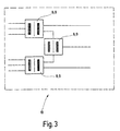
- FIG. 3 is a circuit diagram of an embodiment of the invention Switching device shown.
- the illustration shows the circuit for the two Transmitting / receiving devices 2 of a surveillance zone 1, there are only half of the inner life of the switching device 10 shown in FIG. 1 again.
- the outputs of the receiving channels are about the voting device 8, in which he is in the easiest case a transformer 9 acts, transformed so that the total inductance of the outputs connected in parallel to one of the individual inductors of the Receiving coils 5, 6, 7 corresponds.
- This additional output serves on the one hand to increase the detection sensitivity within the monitoring zone 1 increase; on the other hand, it enables the capacity of the evaluation device optimal use if this originally or alternatively for the evaluation of the Signals from three receiving channels from two receiving devices 4 was designed.
Landscapes
- Engineering & Computer Science (AREA)
- Physics & Mathematics (AREA)
- Signal Processing (AREA)
- Automation & Control Theory (AREA)
- Computer Security & Cryptography (AREA)
- Electromagnetism (AREA)
- General Physics & Mathematics (AREA)
- Burglar Alarm Systems (AREA)
- Alarm Systems (AREA)
Description
Bei Anwendung der zweiten Variante wird eine geringere Detektionsempfindlichkeit erreicht, jedoch lassen sich Störsignale besser erkennen, da sie in den unteren Empfangsspulen einen größeren Signalanteil haben, als in den darüber liegenden Empfangsspulen.
- 1
- Überwachungszone
- 2
- Sende-/Empfangsvorrichtung
- 3
- Sendevorrichtung
- 4a
- erste Empfangsvorrichtung
- 4b
- zweite Empfangsvorrichtung
- 5
- obere Empfangsspule
- 6
- mittlere Empfangsspule
- 7
- untere Empfangsspule
- 8
- Abstimmvorrichtung
- 9
- Transformator
- 10
- Schaltvorrichtung
Claims (5)
- System zur Überwachung von elektromagnetisch gesicherten Artikeln in n Überwachungszonen, wobei n die Anzahl der nebeneinander liegenden Überwachungszonen kennzeichnet und größer oder gleich 2 ist, wobei jede der n Überwachungszonen durch zwei Sende-/Empfangsvorrichtungen definiert ist, die zu beiden Seiten der Überwachungszone angeordnet sind, und wobei jede Sendevorrichtung zumindest eine Sendespule und jede Empfangsvorrichtung m Empfangsspulen aufweist, wobei m die Anzahl der Empfangsspulen kennzeichnet und mindestens gleich 1 ist,
dadurch gekennzeichnet,
daß eine Schaltvorrichtung (10) vorgesehen ist, die die Ausgänge der 2·n Empfangsvorrichtungen (4) auf n Ausgänge reduziert. - System nach Anspruch 1,
dadurch gekennzeichnet,
daß die m Empfangsspulen (5, 6, 7) der 2·n Empfangsvorrichtungen (4) maximal m unterschiedliche Induktivitäten I(m) aufweisen,
daß die Ausgänge der m Empfangsspulen (5, 6, 7) parallel geschaltet sind und
daß eine Abstimmvorrichtung (8) vorgesehen ist, die die Gesamtinduktivität der m Empfangsspulen (5, 6, 7) derart abstimmt, daß sie im wesentlichen einer der Induktivitäten I(m) entspricht - System nach Anspruch 2,
dadurch gekennzeichnet,
daß es sich bei der Abstimmvorrichtung (8) um einen Transformator (9) oder um eine elektronische Schaltung handelt. - System nach Anspruch 1 oder 2,
dadurch gakennzeichnet,
daß die Schaltvorrichtung (10) die Ausgänge der m Empfangsspulen (5, 6, 7) einer Empfangsvorrichtung (4) parallel schaltet. - System nach Anspruch 1 oder 2,
dadurch gekennzeichnet,
daß die Schaltung die Ausgänge korrespondierender Empfangsspulen (5, 6, 7) der Empfangsvorrichtungen (4), die zu beiden Seiten der Überwachungszone (1) angeordnet sind, parallel schaltet.
Applications Claiming Priority (3)
| Application Number | Priority Date | Filing Date | Title |
|---|---|---|---|
| DE19722078A DE19722078A1 (de) | 1997-05-27 | 1997-05-27 | System zur Überwachung von elektromagnetisch gesicherten Artikeln in mehreren Überwachungszonen |
| DE19722078 | 1997-05-27 | ||
| PCT/EP1998/002543 WO1998054680A1 (de) | 1997-05-27 | 1998-04-30 | System zur überwachung von elektromagnetisch gesicherten artikeln in mehreren überwachungszonen |
Publications (2)
| Publication Number | Publication Date |
|---|---|
| EP0985205A1 EP0985205A1 (de) | 2000-03-15 |
| EP0985205B1 true EP0985205B1 (de) | 2001-07-25 |
Family
ID=7830590
Family Applications (1)
| Application Number | Title | Priority Date | Filing Date |
|---|---|---|---|
| EP98924245A Expired - Lifetime EP0985205B1 (de) | 1997-05-27 | 1998-04-30 | System zur überwachung von elektromagnetisch gesicherten artikeln in mehreren überwachungszonen |
Country Status (7)
| Country | Link |
|---|---|
| EP (1) | EP0985205B1 (de) |
| AT (1) | ATE203612T1 (de) |
| AU (1) | AU734882B2 (de) |
| DE (2) | DE19722078A1 (de) |
| DK (1) | DK0985205T3 (de) |
| ES (1) | ES2161535T3 (de) |
| WO (1) | WO1998054680A1 (de) |
Family Cites Families (9)
| Publication number | Priority date | Publication date | Assignee | Title |
|---|---|---|---|---|
| US4751516A (en) * | 1985-01-10 | 1988-06-14 | Lichtblau G J | Antenna system for magnetic and resonant circuit detection |
| US5371490A (en) * | 1989-03-22 | 1994-12-06 | Actron Entwicklungs Ag | System for electronic safeguarding against burglary using multiple transmitters and receivers |
| US5126749A (en) * | 1989-08-25 | 1992-06-30 | Kaltner George W | Individually fed multiloop antennas for electronic security systems |
| US5337040A (en) * | 1991-10-31 | 1994-08-09 | Actron Entwicklungs Ag | Detection apparatus for shoplifting-preventing labels |
| BR9307899A (pt) * | 1993-12-30 | 1996-09-10 | Sensomatic Electronics Corp | Aparelho e processo para gerar sinais de detecção em resposta à presença de elementos sensores magneticamente saturáveis dentro dos limites de uma zona de interrogação |
| NL9400076A (nl) * | 1994-01-17 | 1995-09-01 | Nedap Nv | Diefstaldetectie- en identificatiesysteem. |
| US5627516A (en) * | 1994-09-28 | 1997-05-06 | Sensormatic Electronics Corporation | Electronic article surveillance input configuration control system employing expert system techniques for dynamic optimization |
| DE19503896A1 (de) * | 1995-02-07 | 1996-08-08 | Esselte Meto Int Gmbh | Einrichtung zur Detektierung eines mit einem elektronischen Sicherungselement versehenen Artikels |
| US5600304A (en) * | 1995-11-02 | 1997-02-04 | Sensormatic Electronics Corporation | EAS system with common control station for different personality local stations |
-
1997
- 1997-05-27 DE DE19722078A patent/DE19722078A1/de not_active Withdrawn
-
1998
- 1998-04-30 AT AT98924245T patent/ATE203612T1/de not_active IP Right Cessation
- 1998-04-30 AU AU76508/98A patent/AU734882B2/en not_active Ceased
- 1998-04-30 ES ES98924245T patent/ES2161535T3/es not_active Expired - Lifetime
- 1998-04-30 WO PCT/EP1998/002543 patent/WO1998054680A1/de not_active Ceased
- 1998-04-30 DK DK98924245T patent/DK0985205T3/da active
- 1998-04-30 DE DE59801089T patent/DE59801089D1/de not_active Expired - Fee Related
- 1998-04-30 EP EP98924245A patent/EP0985205B1/de not_active Expired - Lifetime
Also Published As
| Publication number | Publication date |
|---|---|
| DE59801089D1 (de) | 2001-08-30 |
| WO1998054680A1 (de) | 1998-12-03 |
| AU734882B2 (en) | 2001-06-21 |
| AU7650898A (en) | 1998-12-30 |
| DK0985205T3 (da) | 2001-10-22 |
| EP0985205A1 (de) | 2000-03-15 |
| DE19722078A1 (de) | 1998-12-03 |
| ATE203612T1 (de) | 2001-08-15 |
| ES2161535T3 (es) | 2001-12-01 |
Similar Documents
| Publication | Publication Date | Title |
|---|---|---|
| DE69327227T2 (de) | Antennensystem | |
| DE3313245C2 (de) | ||
| DE69227950T3 (de) | Antennensystem zum Empfang von Rundfunk- oder Kommunikationssignalen von einem Satelliten | |
| DE69032053T2 (de) | Antennen-Umschaltsystem | |
| DE3042088C2 (de) | ||
| EP0707762B1 (de) | Mobilfunkantennenanlage | |
| DE69532373T2 (de) | Modulare Verbindungsmatrix für die matrische Verbindung von Antennen mit Funkkanaleinheiten | |
| DE69715347T2 (de) | Filter für mehrere Bandpässe | |
| EP0547563B1 (de) | Leiterplattenantenne | |
| EP0069979B1 (de) | Antennenanpasseinrichtung | |
| DE69211330T2 (de) | Funksende- und -empfangsanordnung | |
| DE3108029A1 (de) | "antennenanlage" | |
| EP1619750B1 (de) | Antennenanordnung für ein RFID-System | |
| DE4027710A1 (de) | Magnetisches antennensystem mit unabhaengig steuerbarer elektrischer feldabschirmung und magnetischer feldabgleichung | |
| EP0218843A2 (de) | Diversity-Antenne für mobile Funkgeräte | |
| EP1357503B1 (de) | Transponder mit abgestimmtem Resonanzkreis | |
| DE102004015925A1 (de) | An einer Oberfläche angebrachte Antennenvorrichtung | |
| EP0907260B1 (de) | Anordnung zur Übertragung, zur Abstrahlung und zum Empfang von Hochfrequenz-Signalen | |
| DE4411233C1 (de) | Frequenzkanal-Multiplexer bzw. -Demultiplexer | |
| DE3528974A1 (de) | Funktelefonnetz fuer ein in funkzellen aufgeteiltes funkgebiet | |
| EP0985205A1 (de) | System zur überwachung von elektromagnetisch gesicherten artikeln in mehreren überwachungszonen | |
| DE10042875C2 (de) | Kommunikationsendgerät | |
| DE4121399C1 (de) | ||
| DE3814748C1 (en) | Waveguide multiplexer or demultiplexer | |
| DE60218901T2 (de) | Verfahren und system zur übertragung von trägersignalen zwischen einem ersten und einem zweiten antennennetzwerk |
Legal Events
| Date | Code | Title | Description |
|---|---|---|---|
| PUAI | Public reference made under article 153(3) epc to a published international application that has entered the european phase |
Free format text: ORIGINAL CODE: 0009012 |
|
| 17P | Request for examination filed |
Effective date: 19991110 |
|
| AK | Designated contracting states |
Kind code of ref document: A1 Designated state(s): AT BE CH CY DE DK ES FI FR GB GR IE IT LI LU MC NL PT SE |
|
| GRAG | Despatch of communication of intention to grant |
Free format text: ORIGINAL CODE: EPIDOS AGRA |
|
| GRAG | Despatch of communication of intention to grant |
Free format text: ORIGINAL CODE: EPIDOS AGRA |
|
| GRAH | Despatch of communication of intention to grant a patent |
Free format text: ORIGINAL CODE: EPIDOS IGRA |
|
| 17Q | First examination report despatched |
Effective date: 20001228 |
|
| GRAH | Despatch of communication of intention to grant a patent |
Free format text: ORIGINAL CODE: EPIDOS IGRA |
|
| GRAA | (expected) grant |
Free format text: ORIGINAL CODE: 0009210 |
|
| AK | Designated contracting states |
Kind code of ref document: B1 Designated state(s): AT BE CH CY DE DK ES FI FR GB GR IE IT LI LU MC NL PT SE |
|
| PG25 | Lapsed in a contracting state [announced via postgrant information from national office to epo] |
Ref country code: IE Free format text: LAPSE BECAUSE OF FAILURE TO SUBMIT A TRANSLATION OF THE DESCRIPTION OR TO PAY THE FEE WITHIN THE PRESCRIBED TIME-LIMIT Effective date: 20010725 |
|
| REF | Corresponds to: |
Ref document number: 203612 Country of ref document: AT Date of ref document: 20010815 Kind code of ref document: T |
|
| REG | Reference to a national code |
Ref country code: CH Ref legal event code: EP |
|
| REG | Reference to a national code |
Ref country code: IE Ref legal event code: FG4D Free format text: GERMAN |
|
| REF | Corresponds to: |
Ref document number: 59801089 Country of ref document: DE Date of ref document: 20010830 |
|
| ITF | It: translation for a ep patent filed | ||
| REG | Reference to a national code |
Ref country code: DK Ref legal event code: T3 |
|
| GBT | Gb: translation of ep patent filed (gb section 77(6)(a)/1977) |
Effective date: 20010927 |
|
| PG25 | Lapsed in a contracting state [announced via postgrant information from national office to epo] |
Ref country code: PT Free format text: LAPSE BECAUSE OF FAILURE TO SUBMIT A TRANSLATION OF THE DESCRIPTION OR TO PAY THE FEE WITHIN THE PRESCRIBED TIME-LIMIT Effective date: 20011025 |
|
| PG25 | Lapsed in a contracting state [announced via postgrant information from national office to epo] |
Ref country code: GR Free format text: LAPSE BECAUSE OF FAILURE TO SUBMIT A TRANSLATION OF THE DESCRIPTION OR TO PAY THE FEE WITHIN THE PRESCRIBED TIME-LIMIT Effective date: 20011026 |
|
| REG | Reference to a national code |
Ref country code: CH Ref legal event code: NV Representative=s name: OK PAT AG PATENTE MARKEN LIZENZEN |
|
| REG | Reference to a national code |
Ref country code: ES Ref legal event code: FG2A Ref document number: 2161535 Country of ref document: ES Kind code of ref document: T3 |
|
| ET | Fr: translation filed | ||
| REG | Reference to a national code |
Ref country code: GB Ref legal event code: IF02 |
|
| PG25 | Lapsed in a contracting state [announced via postgrant information from national office to epo] |
Ref country code: MC Free format text: LAPSE BECAUSE OF NON-PAYMENT OF DUE FEES Effective date: 20020430 Ref country code: LU Free format text: LAPSE BECAUSE OF NON-PAYMENT OF DUE FEES Effective date: 20020430 Ref country code: CY Free format text: LAPSE BECAUSE OF FAILURE TO SUBMIT A TRANSLATION OF THE DESCRIPTION OR TO PAY THE FEE WITHIN THE PRESCRIBED TIME-LIMIT Effective date: 20020430 |
|
| PLBE | No opposition filed within time limit |
Free format text: ORIGINAL CODE: 0009261 |
|
| STAA | Information on the status of an ep patent application or granted ep patent |
Free format text: STATUS: NO OPPOSITION FILED WITHIN TIME LIMIT |
|
| 26N | No opposition filed | ||
| PGFP | Annual fee paid to national office [announced via postgrant information from national office to epo] |
Ref country code: GB Payment date: 20030313 Year of fee payment: 6 Ref country code: AT Payment date: 20030313 Year of fee payment: 6 |
|
| PGFP | Annual fee paid to national office [announced via postgrant information from national office to epo] |
Ref country code: DK Payment date: 20030314 Year of fee payment: 6 |
|
| PGFP | Annual fee paid to national office [announced via postgrant information from national office to epo] |
Ref country code: NL Payment date: 20030318 Year of fee payment: 6 |
|
| PGFP | Annual fee paid to national office [announced via postgrant information from national office to epo] |
Ref country code: FR Payment date: 20030403 Year of fee payment: 6 |
|
| PGFP | Annual fee paid to national office [announced via postgrant information from national office to epo] |
Ref country code: SE Payment date: 20030407 Year of fee payment: 6 |
|
| PGFP | Annual fee paid to national office [announced via postgrant information from national office to epo] |
Ref country code: FI Payment date: 20030411 Year of fee payment: 6 |
|
| PGFP | Annual fee paid to national office [announced via postgrant information from national office to epo] |
Ref country code: ES Payment date: 20030428 Year of fee payment: 6 |
|
| PGFP | Annual fee paid to national office [announced via postgrant information from national office to epo] |
Ref country code: DE Payment date: 20030430 Year of fee payment: 6 |
|
| PGFP | Annual fee paid to national office [announced via postgrant information from national office to epo] |
Ref country code: BE Payment date: 20030514 Year of fee payment: 6 |
|
| PGFP | Annual fee paid to national office [announced via postgrant information from national office to epo] |
Ref country code: CH Payment date: 20030605 Year of fee payment: 6 |
|
| PG25 | Lapsed in a contracting state [announced via postgrant information from national office to epo] |
Ref country code: LI Free format text: LAPSE BECAUSE OF NON-PAYMENT OF DUE FEES Effective date: 20040430 Ref country code: GB Free format text: LAPSE BECAUSE OF NON-PAYMENT OF DUE FEES Effective date: 20040430 Ref country code: FI Free format text: LAPSE BECAUSE OF NON-PAYMENT OF DUE FEES Effective date: 20040430 Ref country code: DK Free format text: LAPSE BECAUSE OF NON-PAYMENT OF DUE FEES Effective date: 20040430 Ref country code: CH Free format text: LAPSE BECAUSE OF NON-PAYMENT OF DUE FEES Effective date: 20040430 Ref country code: BE Free format text: LAPSE BECAUSE OF NON-PAYMENT OF DUE FEES Effective date: 20040430 Ref country code: AT Free format text: LAPSE BECAUSE OF NON-PAYMENT OF DUE FEES Effective date: 20040430 |
|
| PG25 | Lapsed in a contracting state [announced via postgrant information from national office to epo] |
Ref country code: SE Free format text: LAPSE BECAUSE OF NON-PAYMENT OF DUE FEES Effective date: 20040501 |
|
| PG25 | Lapsed in a contracting state [announced via postgrant information from national office to epo] |
Ref country code: ES Free format text: LAPSE BECAUSE OF NON-PAYMENT OF DUE FEES Effective date: 20040503 |
|
| BERE | Be: lapsed |
Owner name: *METO INTERNATIONAL G.M.B.H. Effective date: 20040430 |
|
| PG25 | Lapsed in a contracting state [announced via postgrant information from national office to epo] |
Ref country code: NL Free format text: LAPSE BECAUSE OF NON-PAYMENT OF DUE FEES Effective date: 20041101 |
|
| PG25 | Lapsed in a contracting state [announced via postgrant information from national office to epo] |
Ref country code: DE Free format text: LAPSE BECAUSE OF NON-PAYMENT OF DUE FEES Effective date: 20041103 |
|
| REG | Reference to a national code |
Ref country code: CH Ref legal event code: PL |
|
| GBPC | Gb: european patent ceased through non-payment of renewal fee |
Effective date: 20040430 |
|
| EUG | Se: european patent has lapsed | ||
| PG25 | Lapsed in a contracting state [announced via postgrant information from national office to epo] |
Ref country code: FR Free format text: LAPSE BECAUSE OF NON-PAYMENT OF DUE FEES Effective date: 20041231 |
|
| NLV4 | Nl: lapsed or anulled due to non-payment of the annual fee |
Effective date: 20041101 |
|
| REG | Reference to a national code |
Ref country code: FR Ref legal event code: ST |
|
| PG25 | Lapsed in a contracting state [announced via postgrant information from national office to epo] |
Ref country code: IT Free format text: LAPSE BECAUSE OF NON-PAYMENT OF DUE FEES;WARNING: LAPSES OF ITALIAN PATENTS WITH EFFECTIVE DATE BEFORE 2007 MAY HAVE OCCURRED AT ANY TIME BEFORE 2007. THE CORRECT EFFECTIVE DATE MAY BE DIFFERENT FROM THE ONE RECORDED. Effective date: 20050430 |
|
| REG | Reference to a national code |
Ref country code: ES Ref legal event code: FD2A Effective date: 20040503 |