EP0983882B1 - Anordnung zur Druckmittel-Verbindung insbesondere eines Fahrzeug-Federbeins mit einer Druckversorgungseinheit - Google Patents
Anordnung zur Druckmittel-Verbindung insbesondere eines Fahrzeug-Federbeins mit einer Druckversorgungseinheit Download PDFInfo
- Publication number
- EP0983882B1 EP0983882B1 EP99116147A EP99116147A EP0983882B1 EP 0983882 B1 EP0983882 B1 EP 0983882B1 EP 99116147 A EP99116147 A EP 99116147A EP 99116147 A EP99116147 A EP 99116147A EP 0983882 B1 EP0983882 B1 EP 0983882B1
- Authority
- EP
- European Patent Office
- Prior art keywords
- connector element
- holding part
- wall
- arrangement according
- aperture
- Prior art date
- Legal status (The legal status is an assumption and is not a legal conclusion. Google has not performed a legal analysis and makes no representation as to the accuracy of the status listed.)
- Expired - Lifetime
Links
- 239000000725 suspension Substances 0.000 title description 6
- 239000012530 fluid Substances 0.000 title 1
- 230000008878 coupling Effects 0.000 claims description 10
- 238000010168 coupling process Methods 0.000 claims description 10
- 238000005859 coupling reaction Methods 0.000 claims description 10
- 238000005452 bending Methods 0.000 claims description 7
- 238000003780 insertion Methods 0.000 claims description 6
- 230000037431 insertion Effects 0.000 claims description 6
- 230000007704 transition Effects 0.000 claims description 5
- 230000002787 reinforcement Effects 0.000 claims description 2
- 238000007789 sealing Methods 0.000 claims description 2
- 230000014759 maintenance of location Effects 0.000 claims 1
- 238000010137 moulding (plastic) Methods 0.000 claims 1
- 238000004519 manufacturing process Methods 0.000 description 4
- 229910001369 Brass Inorganic materials 0.000 description 1
- 239000006096 absorbing agent Substances 0.000 description 1
- 230000004323 axial length Effects 0.000 description 1
- 239000010951 brass Substances 0.000 description 1
- 238000002485 combustion reaction Methods 0.000 description 1
- 230000001419 dependent effect Effects 0.000 description 1
- 239000000446 fuel Substances 0.000 description 1
- 238000002347 injection Methods 0.000 description 1
- 239000007924 injection Substances 0.000 description 1
- 238000001746 injection moulding Methods 0.000 description 1
- 239000002184 metal Substances 0.000 description 1
- 238000000465 moulding Methods 0.000 description 1
- 230000035515 penetration Effects 0.000 description 1
- 230000002093 peripheral effect Effects 0.000 description 1
- 238000007639 printing Methods 0.000 description 1
- 230000001681 protective effect Effects 0.000 description 1
- 230000035939 shock Effects 0.000 description 1
- 230000008719 thickening Effects 0.000 description 1
Images


Classifications
-
- B—PERFORMING OPERATIONS; TRANSPORTING
- B60—VEHICLES IN GENERAL
- B60G—VEHICLE SUSPENSION ARRANGEMENTS
- B60G11/00—Resilient suspensions characterised by arrangement, location or kind of springs
- B60G11/26—Resilient suspensions characterised by arrangement, location or kind of springs having fluid springs only, e.g. hydropneumatic springs
- B60G11/27—Resilient suspensions characterised by arrangement, location or kind of springs having fluid springs only, e.g. hydropneumatic springs wherein the fluid is a gas
-
- B—PERFORMING OPERATIONS; TRANSPORTING
- B60—VEHICLES IN GENERAL
- B60G—VEHICLE SUSPENSION ARRANGEMENTS
- B60G2204/00—Indexing codes related to suspensions per se or to auxiliary parts
- B60G2204/10—Mounting of suspension elements
- B60G2204/20—Mounting of accessories, e.g. pump, compressor
- B60G2204/201—Mounting of accessories, e.g. pump, compressor of fluid lines
Definitions
- the present invention relates to an arrangement for connecting pressure lines according to the preamble of patent claim 1, in particular to the pneumatic Connecting a vehicle suspension strut with a pressure supply unit via a Transition piece to a holding part of the shock absorber fastenable connector element, See, for example, EP-A-767080.
- connection arrangements are usually connector elements made of metal, z. As brass used. These connector elements are usually screwed to the holding part or held by special clip elements. This leads to a technically complex production and assembly of the connector elements.
- EPC-forming document EP 0 918 156 A1 describes a one-piece made of plastic existing connector element for fuel lines of an internal combustion engine.
- This connector element can be connected to a printing unit, with an injection system to be locked.
- the connector element has two elastically deformable retaining arms, which a connecting body of the Einspritranlage overlapping latching.
- a plug-in portion of the Connector element inserted into a plug-in opening of the connecting body.
- the present invention is based on the object, in an arrangement of generic type the manufacture and assembly of the connector element considerably simplify.
- the connector element is formed as a one-piece molded part made of plastic and locked to the holder with the holding part.
- This can be the Produce connector element as a mass part very economically by injection molding.
- the locking connection according to the invention allows a particularly fast and economical, preferably automated assembly. In this respect, the invention leads especially with regard to serious advantages that it is in the automotive industry is a mass production.
- the connector element practically acts as a transition piece between a to Pressure supply unit (DVE) leading pressure line and a further to the Suspension strut leading pressure line.
- DVE Pressure supply unit
- the pressure line between the stationary held ner connector element and be designed to be flexible according to the relatively rotatable strut.
- it is a relatively dimensionally stable, made of plastic formed bent pipe between its first, with the connector element connected end and its second, connected to the strut end one circular, coaxial with the strut longitudinal axis course with a Wrap angle preferably in the range between 360 ° and 720 °.
- the described relative rotational movements are then easily possible by the tube due to their helical course elastically expand or can narrow.
- the occurring, acting in the circumferential direction forces are taken up or supported by the connector element according to the invention by
- the latching connection between the connector element and the Holding part is designed at least in this direction is substantially free of play.
- the invention finds particular in one - not even illustrated - vehicle suspension strut application. It deals in particular, an air strut; but it can too working hydropneumatically.
- a strut must over a pressure medium connection with a not shown Pressure supply unit (DVE), preferably air supply unit (LVE).
- DVE Pressure supply unit
- LVE air supply unit
- This connector element 6 serves as a transition piece between a to Suspension strut leading pipeline 8 (see FIGS. 8 and 9) and a not shown, leading to the DVE pressure line.
- the connection of the pipe 8 with the strut is not the subject of the present invention and therefore becomes also not shown and described.
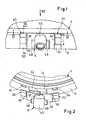
- the invention relates specifically to the Connector element 6, and that is the connector element according to the invention 6 as a one-piece molding made of plastic formed and for mounting with the holding part 4 via a Locking connection connectable.
- the holding part 4 is usually cap-like with a arcuate curved, in particular hollow cylindrical and to the longitudinal axis of the strut coaxial wall 12 (so-called Bulkhead wall).
- This wall 12 has a recess open to the edge towards a free axial side 14 for receiving the connector element 6. in the illustrated embodiment, the recess 14 in essentially rectangular formed (see above all Fig. 5).
- the connector element 6 has at least one corresponding the contour of the recess 14 extending receiving gap 16 (see in particular FIGS. 4 and 6) in such a way, that the connector element 6 in one to the strut longitudinal axis parallel insertion direction (see the arrow 18 in Fig.
- the recess 14 is basically closed by the connector element 6, so that in this area a certain dirt seal is guaranteed.
- the connector element 6 has two lateral, resilient Locking arms 20 on, in the inserted, in the Recess 14 sitting state with locking lugs 22 (FIG. 6) such in addition to the recess 14 arranged latching openings 24 of the wall 12 engage that in the release direction a positive connection is guaranteed (see Fig. 7).
- each locking arm 20 by two angled to each other, in particular approximately at right angles arranged bending axes 26 and 28th elastically deformable (Fig. 3).
- each locking arm 20 seen with the connector element 6 transversely to the insertion direction 18, via a to the peripheral contour of the wall 12 of the Holding part 4 adapted wall portion 30 connected, wherein this wall section 30 elastically around a first, approximately parallel to the strut longitudinal axis extending bending axis 26 is deformable.
- Fig. 4 referenced, wherein the bending direction by arrows 32nd is illustrated.
- each locking arm 20th such as parallel to the longitudinal axis in the insertion direction 18, that it is elastic about a second, to the wall 12 of the holding part 4 approximately tangentially extending bending axis 28 deformable is.
- This bend is shown in FIGS. 6 and 7 by arrows 34 illustrated.
- each latching arm 20 and the remaining connector element 6 a narrow slot 36 is formed is.
- the wall portion 30 above all his lying on the opening side of the recess 14 Edge have a reinforcement, not shown, which as marginal thickening or web or rib contour in particular can be performed on the convex outside.
- the spring behavior of the latching arms 20 in particular influenced in terms of increasing the latching holding force become. It also becomes a good and mechanically durable Completion of the recess 14 in the free edge region of the wall 2 guaranteed.
- each latching arm 20 a the latching lug 22 enclosing Sealing region 38 (see Fig. 6), the in the locked state so to rest on the wall 12 of the Holding parts 4 passes that in the region of the locking openings 24th also a dirt seal is ensured (see also Fig. 7).
- the acting as a transition piece connector element 6 has on the outside of the holding part 4, a coupling piece 40th a fundamentally arbitrary line coupling and on the inside of a connecting element 42 for the strut leading pipe 8 (Fig. 8, 9).
- the neck-like Connecting element 42 preferably has a so-called mandrel profile on ( Figure 6).
- the coupling piece 40 is preferably Part of a plug-in coupling and z. B. formed as a socket part, in an unillustrated plug part inserted is. It can also be an additional screw 46th (Screw cap) if necessary with a mounting protection element 44th be provided (Fig. 8 and 9), practically as an adapter between the female thread having a dome piece 40th and the plug part.
- the protective element 44 protects against penetration of dirt and the like, as yet no Plug is inserted; it is removed before the plug.
- the coupling piece 40 can also be used directly as, for example Be part of a threaded coupling. Due to the preferably circular course of the pipeline 8 (FIG. 8) extends the connection element 42 of the connector element 6 approximately tangential to the course of the pipe 8 in the Interior of the holding part 4; see in particular FIG. 4.
- the connector element 6 at least one abutment element 48. in the illustrated, preferred embodiment is around two web-like, laterally projecting from the coupling piece 40 Abutment elements 48. These serve for temporary purposes Fix, d. H. Holding the connector element 6 in the assembly of connecting parts, to unwanted forces to prevent the connector element 6.
- This is z. B. the case when a screw, z. B. the Screw 46, screwed into the coupling piece 40 is, and / or if a test line for pressure test (so-called Druckprüfrüssel) must be attached.
Landscapes
- Engineering & Computer Science (AREA)
- Mechanical Engineering (AREA)
- Quick-Acting Or Multi-Walled Pipe Joints (AREA)
- Vehicle Body Suspensions (AREA)
Description
- Fig. 1
- eine seitliche Draufsicht auf einen Teilbereich eines Halteteils mit einem montierten erfindungsgemäßen Verbinderelement,
- Fig. 2
- eine Perspektivansicht des Bereichs gemäß Fig. 1 in einer Situation während der Montage (oder Demontage) des Verbinderelementes,
- Fig. 3
- eine Seitenansicht wie in Fig. 1 während der Montage entsprechend Fig. 2,
- Fig. 4
- eine Schnittansicht in der Ebene IV-IV gemäß Fig. 1,
- Fig. 5
- eine weitere Seitenansicht wie in Fig. 1, allerdings ohne Darstellung des Verbinderelementes,
- Fig. 6
- eine vergrößerte Perspektivansicht (nur) des Verbinderelementes aus anderem Blickwinkel,
- Fig. 7
- einen stark vergrößerten Schnitt in der Ebene VII-VII gemäß Fig. 1,
- Fig. 8
- eine Ansicht des Verbinderelementes in Pfeilrichtung VIII gemäß Fig. 1 ohne Halteteil, jedoch mit einer angeschlossenen Rohrleitung zur Verbindung mit einem Federbein, und
- Fig. 9
- eine Ansicht in Pfeilrichtung IX gemäß Fig. 8.
Claims (14)
- Anordnung zum - insbesondere pneumatischen - Verbinden einer zu einem Druckaggregat, insbesondere zu einem Fahrzeug-Federbein, führenden Druckleitung mit einer zu einer Druckversorgungseinheit führenden Druckleitung, mit einem als Übergangsstück mit den beiden Druckleitungen zu verbindenden und an einem eine Wandung (12) aufweisenden Halteteil (4) des Druckaggregates bzw. Federbeins befestigbaren Verbinderelement (6),
dadurch gekennzeichnet, dass das Verbinderelement (6) als einstückiges Formteil aus Kunststoff gebildet und zur Halterung mit dem Halteteil (4) verrastbar ist, wobei das Verbinderelement (6) in eine randoffene Ausnehmung (14) der Wandung (12) des Halteteils (4) einsetzbar ist und dazu mindestens einen entsprechend der Kontur der Ausnehmung (14) der Wandung (12) des Halteteils (4) verlaufenden Aufnahmespalt (16) derart aufweist, dass das Verbinderelement (6) in die Ausnehmung (14) einschiebbar ist und im eingeschobenen Zustand der Öffnungsrand der Ausnehmung (14) in dem Aufnahmespalt (16) des Verbinderelementes (6) sitzt. - Anordnung nach Anspruch 1,
dadurch gekennzeichnet, dass das Verbinderelement (6) zum Einsetzen in die randoffene Ausnehmung (14) der gekrümmt, insbesondere hohlzylindrisch ausgebildeten Wandung (12) des Halteteils (4) ausgelegt ist. - Anordnung nach Anspruch 1 oder 2,
dadurch gekennzeichnet, dass dasVerbinderelement(6)in einer zur Längsachse des Federbeins parallel verlaufenden Einschubrichtung (18) in die Ausnehmung (14) einschiebbar ist. - Anordnung nach einem der Ansprüche 1 bis 3,
dadurch gekennzeichnet, daß das Verbinderelement (6) zwei seitliche, federelastische Rastarme (20) aufweist, die im eingeschobenen, in der Ausnehmung (14) sitzenden Zustand mit Rastnasen (22) in neben der Ausnehmung (14) angeordnete Rastöffnungen (24) der Wandung (12) des Halteteils (4) eingreifen. - Anordnung nach Anspruch 4,
dadurch gekennzeichnet, daß jeder Rastarm (20) um zwei zueinander winklig, insbesondere etwa rechtwinklig angeordnete Biegeachsen (26, 28) elastisch verformbar ist. - Anordnung nach Anspruch 4 oder 5,
dadurch gekennzeichnet, daß jeder Rastarm (20) mit dem Verbinderelement (6) quer zur Einschubrichtung (18) über einen an die Umfangskontur der Wandung (12) des Halteteils (4) angepaßten, elastisch um eine erste, etwa parallel zur Längsachse verlaufende Biegeachse (26) verformbaren Wandungsabschnitt (30) verbunden ist. - Anordnung nach Anspruch 6,
dadurch gekennzeichnet, daß der die randoffene Ausnehmung (14) der Wandung (12) des Halteteils (4) im eingesetzten Zustand im wesentlichen verschließende Wandungsabschnitt (30) insbesondere auf seiner konvexen, an die Krümmung der Wandung (12) angepaßten Außenseite steg- oder rippenartige Verstärkungen aufweist. - Anordnung nach Anspruch 6 oder 7,
dadurch gekennzeichnet, daß sich jeder Rastarm (20) im Anschluß an den zugehörigen Wandungsabschnitt derart etwa parallel zur Längsachse und insbesondere in Einschubrichtung (18) erstreckt, daß er elastisch um eine zweite, zur Wandung (12) des Halteteils (4) etwa tangential verlaufende Biegeachse (28) verformbar ist. - Anordnung nach einem der Ansprüche 4 bis 8,
dadurch gekennzeichnet, daß jeder Rastarm (20) einen die am freien Ende angeordnete Rastnase (22) umschließenden Dichtbereich (38) aufweist, der im mit dem Halteteil (4) verrasteten Zustand so zur Anlage an der Wandung (12) des Halteteils (4) gelangt, daß im Bereich der Rastöffnungen (24) eine Schmutzdichtung gewährleistet ist. - Anordnung nach einem der Ansprüche 1 bis 9,
dadurch gekennzeichnet, daß das Verbinderelement (6) auf der Außenseite des Halteteils (4) ein Kuppelstück (40) einer Leitungskupplung sowie auf der Innenseite ein Anschlußelement (42) für eine zu dem Federbein führende Rohrleitung (8) aufweist. - Anordnung nach Anspruch 10,
dadurch gekennzeichnet, daß die Rohrleitung (8) zwischen ihrem ersten, mit dem Verbinderelement (6) zu verbindenden Ende und ihrem zweiten, zu dem Federbein führenden Ende einen kreisförmigen, zur Federbein-Längsachse koaxialen Verlauf mit einem Umschlingungswinkel vorzugsweise im Bereich zwischen 360° und 720° aufweist. - Anordnung nach Anspruch 10 oder 11,
dadurch gekennzeichnet, daß das Anschlußelement (42) des Verbinderelementes (6) sich etwa tangential zu dem kreisförmigen Verlauf der Rohrleitung (8) in den Innenbereich des Halteteils (4) erstreckt. - Anordnung nach einem der Ansprüche 1 bis 12,
dadurch gekennzeichnet, daß die Verbindung zwischen dem Halteteil (4) und dem Verbinderelement (6) insbesondere in Umfangsrichtung der Wandung (12) im wesentlichen spielfrei ist. - Anordnung nach einem der Ansprüche 1 bis 13,
dadurch gekennzeichnet, daß das Verbinderelement (6) mindestens ein Widerlagerelement (48) zum vorübergehenden zusätzlichen mechanischen Fixieren bzw. Festhalten während bestimmter, das Verbinderelement (6) mit einer Kraft beaufschlagender Vorgänge aufweist.
Applications Claiming Priority (2)
| Application Number | Priority Date | Filing Date | Title |
|---|---|---|---|
| DE29815404 | 1998-08-27 | ||
| DE29815404U | 1998-08-27 |
Publications (3)
| Publication Number | Publication Date |
|---|---|
| EP0983882A2 EP0983882A2 (de) | 2000-03-08 |
| EP0983882A3 EP0983882A3 (de) | 2003-07-30 |
| EP0983882B1 true EP0983882B1 (de) | 2005-10-26 |
Family
ID=8061866
Family Applications (1)
| Application Number | Title | Priority Date | Filing Date |
|---|---|---|---|
| EP99116147A Expired - Lifetime EP0983882B1 (de) | 1998-08-27 | 1999-08-19 | Anordnung zur Druckmittel-Verbindung insbesondere eines Fahrzeug-Federbeins mit einer Druckversorgungseinheit |
Country Status (2)
| Country | Link |
|---|---|
| EP (1) | EP0983882B1 (de) |
| DE (1) | DE59912701D1 (de) |
Families Citing this family (1)
| Publication number | Priority date | Publication date | Assignee | Title |
|---|---|---|---|---|
| DE102005044210A1 (de) * | 2005-09-15 | 2007-03-22 | Continental Aktiengesellschaft | System, bestehend aus einer Luftfeder und einem Träger für die Luftfeder |
Family Cites Families (3)
| Publication number | Priority date | Publication date | Assignee | Title |
|---|---|---|---|---|
| DE8710356U1 (de) * | 1987-07-28 | 1988-09-15 | Tucker Gmbh, 6300 Giessen | Halteclip aus Kunststoff |
| JP3388957B2 (ja) * | 1995-10-02 | 2003-03-24 | ヤマハ発動機株式会社 | 油圧式緩衝器用油圧管連結装置 |
| FR2771472B1 (fr) * | 1997-11-21 | 2000-01-14 | Renault | Raccord encliquetable notamment pour conduites de carburant |
-
1999
- 1999-08-19 EP EP99116147A patent/EP0983882B1/de not_active Expired - Lifetime
- 1999-08-19 DE DE59912701T patent/DE59912701D1/de not_active Expired - Fee Related
Also Published As
| Publication number | Publication date |
|---|---|
| DE59912701D1 (de) | 2005-12-01 |
| EP0983882A2 (de) | 2000-03-08 |
| EP0983882A3 (de) | 2003-07-30 |
Similar Documents
| Publication | Publication Date | Title |
|---|---|---|
| EP0816151B1 (de) | Kraftstoffbehälter | |
| EP0665402B1 (de) | Steckkupplung für Druckleitungssysteme | |
| EP0225480B1 (de) | Fahrzeugscheinwerfer | |
| EP1575812B1 (de) | Verbindungsanordnung einer wischvorrichtung für scheiben von kraftfahrzeugen | |
| EP1996414B1 (de) | Ventilanordnung und bausatz für eine ventilanordnung | |
| DE102006062894B4 (de) | Schutzkappe | |
| DE102007006588B4 (de) | Schnellverschlusskupplung | |
| WO2019072556A1 (de) | Winkelkupplung | |
| WO2021190897A1 (de) | Steckverbinder mit vormontagesicherung | |
| WO2008128923A1 (de) | Anschlussvorrichtung für medienleitungen im bereich einer wandungsdurchführung sowie wandungselement | |
| DE3509831C2 (de) | Reflektorbefestigung für Kraftfahrzeugscheinwerfer | |
| EP1559605B1 (de) | Verlustsicherung für einen Behälterdeckel | |
| DE102012000602A1 (de) | Gelenkeinheit eines Kraftfahrzeugs und Verfahren zu deren Herstellung | |
| DE2819624A1 (de) | Vorstecker fuer wellen, achsen u.dgl. | |
| DE202017006800U1 (de) | Innenliegende Zugentlastung für einen Steckverbinder | |
| EP0271676A1 (de) | Kugelgelenk | |
| DE102020211438A1 (de) | Dichtbuchse zur dichtenden Verbindung von Leitungsendstücken | |
| WO2003045717A2 (de) | Gelenk | |
| DE3235125C2 (de) | ||
| DE9409427U1 (de) | Kraftstoffleitungsverbindungsteil | |
| DE2840648B2 (de) | Anschlußverbindungsstück für Leitungen zum Führen von gasförmigen oder flüssigen Medien | |
| EP0983882A2 (de) | Anordnung zur Druckmittel-Verbindung insbesondere eines Fahrzeug-Federbeins mit einer Druckversorgungseinheit | |
| EP3544718A1 (de) | Demontagewerkzeug für einen filtereinsatz eines flüssigkeitsfilters | |
| DE102020126507A1 (de) | Steckverbinder mit Rückstellelement | |
| DE102020131734A1 (de) | Leuchtenklemme mit Verschlusstülle |
Legal Events
| Date | Code | Title | Description |
|---|---|---|---|
| PUAI | Public reference made under article 153(3) epc to a published international application that has entered the european phase |
Free format text: ORIGINAL CODE: 0009012 |
|
| AK | Designated contracting states |
Kind code of ref document: A2 Designated state(s): AT BE CH CY DE DK ES FI FR GB GR IE IT LI LU MC NL PT SE |
|
| AX | Request for extension of the european patent |
Free format text: AL;LT;LV;MK;RO;SI |
|
| EL | Fr: translation of claims filed | ||
| RAP1 | Party data changed (applicant data changed or rights of an application transferred) |
Owner name: ARMATURENFABRIK HERMANN VOSS GMBH + CO. KG |
|
| RAP1 | Party data changed (applicant data changed or rights of an application transferred) |
Owner name: VOSS AUTOMOTIVE GMBH |
|
| PUAL | Search report despatched |
Free format text: ORIGINAL CODE: 0009013 |
|
| AK | Designated contracting states |
Designated state(s): AT BE CH CY DE DK ES FI FR GB GR IE IT LI LU MC NL PT SE |
|
| AX | Request for extension of the european patent |
Extension state: AL LT LV MK RO SI |
|
| 17P | Request for examination filed |
Effective date: 20040116 |
|
| R17P | Request for examination filed (corrected) |
Effective date: 20040117 |
|
| 17Q | First examination report despatched |
Effective date: 20040218 |
|
| AKX | Designation fees paid |
Designated state(s): DE FR GB IT |
|
| GRAP | Despatch of communication of intention to grant a patent |
Free format text: ORIGINAL CODE: EPIDOSNIGR1 |
|
| GRAS | Grant fee paid |
Free format text: ORIGINAL CODE: EPIDOSNIGR3 |
|
| GRAA | (expected) grant |
Free format text: ORIGINAL CODE: 0009210 |
|
| AK | Designated contracting states |
Kind code of ref document: B1 Designated state(s): DE FR GB IT |
|
| PG25 | Lapsed in a contracting state [announced via postgrant information from national office to epo] |
Ref country code: IT Free format text: LAPSE BECAUSE OF FAILURE TO SUBMIT A TRANSLATION OF THE DESCRIPTION OR TO PAY THE FEE WITHIN THE PRESCRIBED TIME-LIMIT;WARNING: LAPSES OF ITALIAN PATENTS WITH EFFECTIVE DATE BEFORE 2007 MAY HAVE OCCURRED AT ANY TIME BEFORE 2007. THE CORRECT EFFECTIVE DATE MAY BE DIFFERENT FROM THE ONE RECORDED. Effective date: 20051026 |
|
| REG | Reference to a national code |
Ref country code: GB Ref legal event code: FG4D Free format text: NOT ENGLISH |
|
| REF | Corresponds to: |
Ref document number: 59912701 Country of ref document: DE Date of ref document: 20051201 Kind code of ref document: P |
|
| GBT | Gb: translation of ep patent filed (gb section 77(6)(a)/1977) |
Effective date: 20060119 |
|
| ET | Fr: translation filed | ||
| PLBE | No opposition filed within time limit |
Free format text: ORIGINAL CODE: 0009261 |
|
| STAA | Information on the status of an ep patent application or granted ep patent |
Free format text: STATUS: NO OPPOSITION FILED WITHIN TIME LIMIT |
|
| 26N | No opposition filed |
Effective date: 20060727 |
|
| PGFP | Annual fee paid to national office [announced via postgrant information from national office to epo] |
Ref country code: FR Payment date: 20080818 Year of fee payment: 10 |
|
| PGFP | Annual fee paid to national office [announced via postgrant information from national office to epo] |
Ref country code: DE Payment date: 20081027 Year of fee payment: 10 |
|
| REG | Reference to a national code |
Ref country code: FR Ref legal event code: ST Effective date: 20100430 |
|
| PG25 | Lapsed in a contracting state [announced via postgrant information from national office to epo] |
Ref country code: FR Free format text: LAPSE BECAUSE OF NON-PAYMENT OF DUE FEES Effective date: 20090831 Ref country code: DE Free format text: LAPSE BECAUSE OF NON-PAYMENT OF DUE FEES Effective date: 20100302 |
|
| PGFP | Annual fee paid to national office [announced via postgrant information from national office to epo] |
Ref country code: GB Payment date: 20140820 Year of fee payment: 16 |
|
| GBPC | Gb: european patent ceased through non-payment of renewal fee |
Effective date: 20150819 |
|
| PG25 | Lapsed in a contracting state [announced via postgrant information from national office to epo] |
Ref country code: GB Free format text: LAPSE BECAUSE OF NON-PAYMENT OF DUE FEES Effective date: 20150819 |