EP0983753B1 - Kompakter Stent - Google Patents
Kompakter Stent Download PDFInfo
- Publication number
- EP0983753B1 EP0983753B1 EP99115265.3A EP99115265A EP0983753B1 EP 0983753 B1 EP0983753 B1 EP 0983753B1 EP 99115265 A EP99115265 A EP 99115265A EP 0983753 B1 EP0983753 B1 EP 0983753B1
- Authority
- EP
- European Patent Office
- Prior art keywords
- web
- stent
- webs
- patterns
- stent according
- Prior art date
- Legal status (The legal status is an assumption and is not a legal conclusion. Google has not performed a legal analysis and makes no representation as to the accuracy of the status listed.)
- Expired - Lifetime
Links
- 239000000463 material Substances 0.000 claims description 3
- 229910001000 nickel titanium Inorganic materials 0.000 claims description 2
- 238000010276 construction Methods 0.000 description 3
- 238000002513 implantation Methods 0.000 description 3
- 238000004904 shortening Methods 0.000 description 2
- 208000031481 Pathologic Constriction Diseases 0.000 description 1
- 238000010521 absorption reaction Methods 0.000 description 1
- 239000000560 biocompatible material Substances 0.000 description 1
- 230000015572 biosynthetic process Effects 0.000 description 1
- 210000004204 blood vessel Anatomy 0.000 description 1
- 230000001419 dependent effect Effects 0.000 description 1
- 238000011161 development Methods 0.000 description 1
- 230000018109 developmental process Effects 0.000 description 1
- 238000000034 method Methods 0.000 description 1
- 230000000717 retained effect Effects 0.000 description 1
- 208000037804 stenosis Diseases 0.000 description 1
- 230000036262 stenosis Effects 0.000 description 1
- 230000002792 vascular Effects 0.000 description 1
Images

Classifications
-
- A—HUMAN NECESSITIES
- A61—MEDICAL OR VETERINARY SCIENCE; HYGIENE
- A61F—FILTERS IMPLANTABLE INTO BLOOD VESSELS; PROSTHESES; DEVICES PROVIDING PATENCY TO, OR PREVENTING COLLAPSING OF, TUBULAR STRUCTURES OF THE BODY, e.g. STENTS; ORTHOPAEDIC, NURSING OR CONTRACEPTIVE DEVICES; FOMENTATION; TREATMENT OR PROTECTION OF EYES OR EARS; BANDAGES, DRESSINGS OR ABSORBENT PADS; FIRST-AID KITS
- A61F2/00—Filters implantable into blood vessels; Prostheses, i.e. artificial substitutes or replacements for parts of the body; Appliances for connecting them with the body; Devices providing patency to, or preventing collapsing of, tubular structures of the body, e.g. stents
- A61F2/82—Devices providing patency to, or preventing collapsing of, tubular structures of the body, e.g. stents
- A61F2/86—Stents in a form characterised by the wire-like elements; Stents in the form characterised by a net-like or mesh-like structure
- A61F2/90—Stents in a form characterised by the wire-like elements; Stents in the form characterised by a net-like or mesh-like structure characterised by a net-like or mesh-like structure
- A61F2/91—Stents in a form characterised by the wire-like elements; Stents in the form characterised by a net-like or mesh-like structure characterised by a net-like or mesh-like structure made from perforated sheets or tubes, e.g. perforated by laser cuts or etched holes
- A61F2/915—Stents in a form characterised by the wire-like elements; Stents in the form characterised by a net-like or mesh-like structure characterised by a net-like or mesh-like structure made from perforated sheets or tubes, e.g. perforated by laser cuts or etched holes with bands having a meander structure, adjacent bands being connected to each other
-
- A—HUMAN NECESSITIES
- A61—MEDICAL OR VETERINARY SCIENCE; HYGIENE
- A61F—FILTERS IMPLANTABLE INTO BLOOD VESSELS; PROSTHESES; DEVICES PROVIDING PATENCY TO, OR PREVENTING COLLAPSING OF, TUBULAR STRUCTURES OF THE BODY, e.g. STENTS; ORTHOPAEDIC, NURSING OR CONTRACEPTIVE DEVICES; FOMENTATION; TREATMENT OR PROTECTION OF EYES OR EARS; BANDAGES, DRESSINGS OR ABSORBENT PADS; FIRST-AID KITS
- A61F2/00—Filters implantable into blood vessels; Prostheses, i.e. artificial substitutes or replacements for parts of the body; Appliances for connecting them with the body; Devices providing patency to, or preventing collapsing of, tubular structures of the body, e.g. stents
- A61F2/82—Devices providing patency to, or preventing collapsing of, tubular structures of the body, e.g. stents
- A61F2/86—Stents in a form characterised by the wire-like elements; Stents in the form characterised by a net-like or mesh-like structure
- A61F2/90—Stents in a form characterised by the wire-like elements; Stents in the form characterised by a net-like or mesh-like structure characterised by a net-like or mesh-like structure
- A61F2/91—Stents in a form characterised by the wire-like elements; Stents in the form characterised by a net-like or mesh-like structure characterised by a net-like or mesh-like structure made from perforated sheets or tubes, e.g. perforated by laser cuts or etched holes
- A61F2/915—Stents in a form characterised by the wire-like elements; Stents in the form characterised by a net-like or mesh-like structure characterised by a net-like or mesh-like structure made from perforated sheets or tubes, e.g. perforated by laser cuts or etched holes with bands having a meander structure, adjacent bands being connected to each other
- A61F2002/91508—Stents in a form characterised by the wire-like elements; Stents in the form characterised by a net-like or mesh-like structure characterised by a net-like or mesh-like structure made from perforated sheets or tubes, e.g. perforated by laser cuts or etched holes with bands having a meander structure, adjacent bands being connected to each other the meander having a difference in amplitude along the band
-
- A—HUMAN NECESSITIES
- A61—MEDICAL OR VETERINARY SCIENCE; HYGIENE
- A61F—FILTERS IMPLANTABLE INTO BLOOD VESSELS; PROSTHESES; DEVICES PROVIDING PATENCY TO, OR PREVENTING COLLAPSING OF, TUBULAR STRUCTURES OF THE BODY, e.g. STENTS; ORTHOPAEDIC, NURSING OR CONTRACEPTIVE DEVICES; FOMENTATION; TREATMENT OR PROTECTION OF EYES OR EARS; BANDAGES, DRESSINGS OR ABSORBENT PADS; FIRST-AID KITS
- A61F2/00—Filters implantable into blood vessels; Prostheses, i.e. artificial substitutes or replacements for parts of the body; Appliances for connecting them with the body; Devices providing patency to, or preventing collapsing of, tubular structures of the body, e.g. stents
- A61F2/82—Devices providing patency to, or preventing collapsing of, tubular structures of the body, e.g. stents
- A61F2/86—Stents in a form characterised by the wire-like elements; Stents in the form characterised by a net-like or mesh-like structure
- A61F2/90—Stents in a form characterised by the wire-like elements; Stents in the form characterised by a net-like or mesh-like structure characterised by a net-like or mesh-like structure
- A61F2/91—Stents in a form characterised by the wire-like elements; Stents in the form characterised by a net-like or mesh-like structure characterised by a net-like or mesh-like structure made from perforated sheets or tubes, e.g. perforated by laser cuts or etched holes
- A61F2/915—Stents in a form characterised by the wire-like elements; Stents in the form characterised by a net-like or mesh-like structure characterised by a net-like or mesh-like structure made from perforated sheets or tubes, e.g. perforated by laser cuts or etched holes with bands having a meander structure, adjacent bands being connected to each other
- A61F2002/91533—Stents in a form characterised by the wire-like elements; Stents in the form characterised by a net-like or mesh-like structure characterised by a net-like or mesh-like structure made from perforated sheets or tubes, e.g. perforated by laser cuts or etched holes with bands having a meander structure, adjacent bands being connected to each other characterised by the phase between adjacent bands
-
- A—HUMAN NECESSITIES
- A61—MEDICAL OR VETERINARY SCIENCE; HYGIENE
- A61F—FILTERS IMPLANTABLE INTO BLOOD VESSELS; PROSTHESES; DEVICES PROVIDING PATENCY TO, OR PREVENTING COLLAPSING OF, TUBULAR STRUCTURES OF THE BODY, e.g. STENTS; ORTHOPAEDIC, NURSING OR CONTRACEPTIVE DEVICES; FOMENTATION; TREATMENT OR PROTECTION OF EYES OR EARS; BANDAGES, DRESSINGS OR ABSORBENT PADS; FIRST-AID KITS
- A61F2/00—Filters implantable into blood vessels; Prostheses, i.e. artificial substitutes or replacements for parts of the body; Appliances for connecting them with the body; Devices providing patency to, or preventing collapsing of, tubular structures of the body, e.g. stents
- A61F2/82—Devices providing patency to, or preventing collapsing of, tubular structures of the body, e.g. stents
- A61F2/86—Stents in a form characterised by the wire-like elements; Stents in the form characterised by a net-like or mesh-like structure
- A61F2/90—Stents in a form characterised by the wire-like elements; Stents in the form characterised by a net-like or mesh-like structure characterised by a net-like or mesh-like structure
- A61F2/91—Stents in a form characterised by the wire-like elements; Stents in the form characterised by a net-like or mesh-like structure characterised by a net-like or mesh-like structure made from perforated sheets or tubes, e.g. perforated by laser cuts or etched holes
- A61F2/915—Stents in a form characterised by the wire-like elements; Stents in the form characterised by a net-like or mesh-like structure characterised by a net-like or mesh-like structure made from perforated sheets or tubes, e.g. perforated by laser cuts or etched holes with bands having a meander structure, adjacent bands being connected to each other
- A61F2002/9155—Adjacent bands being connected to each other
- A61F2002/91558—Adjacent bands being connected to each other connected peak to peak
-
- A—HUMAN NECESSITIES
- A61—MEDICAL OR VETERINARY SCIENCE; HYGIENE
- A61F—FILTERS IMPLANTABLE INTO BLOOD VESSELS; PROSTHESES; DEVICES PROVIDING PATENCY TO, OR PREVENTING COLLAPSING OF, TUBULAR STRUCTURES OF THE BODY, e.g. STENTS; ORTHOPAEDIC, NURSING OR CONTRACEPTIVE DEVICES; FOMENTATION; TREATMENT OR PROTECTION OF EYES OR EARS; BANDAGES, DRESSINGS OR ABSORBENT PADS; FIRST-AID KITS
- A61F2230/00—Geometry of prostheses classified in groups A61F2/00 - A61F2/26 or A61F2/82 or A61F9/00 or A61F11/00 or subgroups thereof
- A61F2230/0002—Two-dimensional shapes, e.g. cross-sections
- A61F2230/0028—Shapes in the form of latin or greek characters
- A61F2230/0054—V-shaped
Definitions
- the invention relates to a stent according to the preamble of claim 1.
- a stent is known from DE 297 02 671 U known.
- stents form a vascular prosthesis, which consists of biocompatible material.
- Stents are generally used to dilate hollow vessels, such as blood vessels, or body orifices and to keep in an expanded state.
- the stent is normally positioned in a non-expanded state in the body of the patient in a narrowed hollow vessel and subsequently expanded by suitable means, such as a balloon catheter.
- suitable means such as a balloon catheter.
- the stent body consists of a web structure, wherein the web structure has a plurality of mutually adjacent web patterns, which have adjacent to each other webs and which are interconnected by means of connecting elements.
- each of the webs of the web pattern has three sections, which are arranged at an angle to each other, ensures that when widening the angle between the Partial areas become larger, which minimizes the shrinkage of the stent during expansion, if not almost eliminated.
- the stent according to the invention preferably in the unexpanded state, preferably has a high degree of flexibility, which very advantageously influences its ability to be guided within the vessel up to the point of implantation, for example in the crimped state on a catheter. Furthermore, the construction of the invention allows a very stable construction in the expanded state, so that the implanted stent can absorb high forces and thus can exert a very good support function in the implanted state.
- the webs are divided into a central portion and two side portions, which adjoin the ends of the central portion.
- the lateral portions preferably occupy obtuse angles to the central portion.
- the arrangement of the three subregions to each other is preferably made so that a bowl or divider-like configuration is achieved.
- This configuration allows for a very compact shape when the stent crimps together, as the ridges nestle into each other in a manner similar to one another in stacked plates.
- the web patterns are connected to each other by connecting elements which are formed as rectilinear webs.
- the orientation of the connecting elements between two adjacent web patterns is the same in each case. That is, overlying fasteners each have the same orientation.
- the orientations of the connecting elements alternately change between any two adjacent ridge patterns so that, for example, when viewing a wall of a stent unwound in the plane, it alternately aligns the connecting elements once upwards and downwards once.
- the stent according to the invention has the particular advantage that, depending on the use of the material, it can be designed either as a self-expanding stent or as an expandable stent by means of a balloon catheter. In both cases, its advantageous previously explained properties are retained. If a self-expanding stent is desired, it is preferable to use a nickel-titanium alloy as the material.
- the subregions of each web are rectilinear.
- the rectilinear webs run in a straight line into connecting sections of the web patterns, which in each case connect adjacent webs to one another.
- a stent 1 is shown with a tubular flexible body 2 in a perspective schematically simplified representation.
- the tubular flexible body 2 in turn, has a wall 3 with a web structure which will be described below with reference to FIGS Fig. 2 to 4 will be explained in detail.
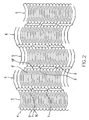
- Fig. 2 the web structure 4 is shown in the unexpanded state.
- the web structure 4 has adjacent web patterns 5, 6, which are arranged alternately next to one another, so that the web patterns according to the in Fig. 2 shown section in the order 5, 6, 5, 6, 5, 6, etc. are arranged.
- Fig. 2 illustrates here that the web patterns 5 and 6 have each other adjacent webs 9 and 10.
- the design of these webs 9, 10 will be described in more detail below, Fig. 2 illustrates, however, that the webs 9, 10 have a plate-like or bowl-like design and according to the in Fig. 2 open the selected display.
- the webs 9 ', 10' of the adjacent web pattern 6 have the same plate or dish-shaped design, but open according to Fig. 2 downward.
- the web patterns 5, 6 are each connected to one another by means of connecting elements 7 between the web patterns 5 and 6 or connecting elements 8 between the web patterns 6 and 5.
- Fig. 2 illustrates here that in each case a plurality of connecting elements 7 between the web patterns 5 and 6 or 8 are provided between the web patterns 6 and 5, in Fig. 2 however, only two connecting elements are shown due to the cutout.
- the connecting elements 7 in this case all have the same orientation, which according to the in Fig. 2 selected representation runs from bottom left to top right.
- the connecting elements 8 also have the same alignment with each other, but run according to the in Fig. 2 selected representation (a settlement of the wall in the plane of Fig. 2 ) from top left to bottom right. This orientation changes alternately between the web patterns 5, 6 and 6, 5, as is apparent from Fig. 2 results.
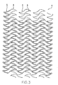
- Fig. 3 illustrates the expanded state of the stent 1 in turn with reference to a section of the web structure 4 in a in the plane of Fig. 3 developed representation of the wall 3 of the body 2 of the stent first
- Fig. 3 illustrates here the spread of the web structure 4, which gives the stent in the expanded position a high degree of autonomy, which allows the stent 1 in this expanded position and the absorption of radial forces, as for example in the implantation of the stent 1 in a hollow vessel in the Area of a stenosis are included.
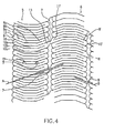
- Fig. 4 is an enlarged view of a section of the web structure 4 in the state according to Fig. 2 shown.
- Fig. 4 illustrates here that the webs 9, 10 each have three subregions 9a to 9c and 10a to 10c.
- the portions 9a to 9c are respectively formed in a straight line and adjoin each other to form the aforementioned dish-like configuration.
- the partial regions 9a and 9b in this case include an obtuse angle ⁇ .
- the middle portion 9b and the right portion 9c include an obtuse angle ⁇ .
- Fig. 4 illustrates here that the webs 9 and 10, which adjoin one another alternately, are arranged in each case like stacked plates in the non-expanded state of the stent 1.
- Fig. 4 shows here that the above-described configuration of the subregions of the webs of course applies to each of the webs together the in Fig. 1 form a tubular state of the wall of the stent 1 with the described web structure.
- the webs 9, 10 are interconnected in each case via rounded connecting sections 12, of which in Fig. 4 representatively a connecting portion 12 is shown.
- FIG. 4 again the arrangement of the connecting elements 7, 8.
- the connecting elements 7 between the web pattern 5 and the adjacent web pattern 6 have in the in Fig. 4 selected representation of an orientation A, each with each other, ie in all the connecting elements 7 is the same.
- the orientation A is indicated by a straight line in Fig. 4 symbolizes and proceeds according to Fig. 4 from bottom left to top right.
- the orientation of the connecting elements 8 is shown by the line B and extends from top left to bottom right.
- the alignment of all fasteners 8 with each other is the same. Consequently, an alternatingly varying orientation A, B, A, B results over the entire web structure.
- the connecting elements 7, 8 are each formed as straight webs, which in a connecting portion 11 of the web pattern 5 and 11 'of the web pattern 6 pass straight, which in Fig. 4 is symbolically represented by a connecting element 7 with its adjacent connecting portions 11 and 11 'for all other connecting elements 7 as well as 8.
- the stent By forming the webs consisting of three sections and the angles ⁇ , ⁇ arranged between them, which are obtuse-angled, results in in Fig. 3 shown spread an enlargement of these angles ⁇ , ⁇ , which results in a particularly advantageous manner, the force-absorbing capacity of the stent in the expanded position.
- the stent In the unexpanded position, the stent is very flexible, so that it passes very well when passing through body vessels Can accommodate curvatures, so that the implantation process is greatly facilitated.
Landscapes
- Health & Medical Sciences (AREA)
- Engineering & Computer Science (AREA)
- Biomedical Technology (AREA)
- Heart & Thoracic Surgery (AREA)
- Life Sciences & Earth Sciences (AREA)
- Cardiology (AREA)
- Oral & Maxillofacial Surgery (AREA)
- Transplantation (AREA)
- Physics & Mathematics (AREA)
- Vascular Medicine (AREA)
- Optics & Photonics (AREA)
- Animal Behavior & Ethology (AREA)
- General Health & Medical Sciences (AREA)
- Public Health (AREA)
- Veterinary Medicine (AREA)
- Prostheses (AREA)
- Media Introduction/Drainage Providing Device (AREA)
- Materials For Medical Uses (AREA)
Description
- Die Erfindung betrifft einen Stent nach dem Oberbegriff des Anspruches 1. Ein derartiger Stent ist aus der
DE 297 02 671 U bekannt. - Aus dem Stand der Technik (z.B.
WO 97/14375 A WO 99/39660 A1 WO 96/26689 A1 - Ein grundlegendes Problem bei vielen Stentkonstruktionen besteht darin, daß sie sich beim Aufweiten verkürzen. Die Verkürzung ist jedoch unerwünscht, da hierbei nicht ausgeschlossen werden kann, daß der aufgeweitete Stent aufgrund seiner Verkürzung den gesamten Bereich innerhalb des Gefäßes oder der Körperöffnung erfaßt, den er beispielsweise aufweiten und stützen soll, nicht mehr abdeckt.
- Es ist daher Aufgabe der vorliegenden Erfindung, einen Stent der im Oberbegriff des Anspruchs 1 angegebenen Art zu schaffen, der im nicht-expandierten Zustand flexibel ist, im expandierten Zustand ausreichende Haltekräfte aufbaut, um in diesem Zustand zu verharren und dabei seine Länge beim Expandieren möglichst wenig verringert.
- Die Lösung dieser Aufgabe erfolgt durch die Merkmale des Anspruches 1.
- Dadurch, daß jeder der Stege der Stegmuster drei Teilbereiche aufweist, die im Winkel zueinander angeordnet sind, wird erreicht, daß beim Aufweiten die Winkel zwischen den Teilbereichen größer werden, was die Schrumpfung des Stents beim Aufweiten minimiert wenn nicht gar nahezu eliminiert.
- Bei dieser Konstruktion weist der erfindungsgemäße Stent vorzugsweise im nicht-expandierten Zustand eine hohe Flexibilität auf, die seine Führbarkeit innerhalb des Gefäßes bis zur Implantationsstelle, beispielsweise im aufgekrimmten Zustand auf einem Katheter, sehr vorteilhaft beeinflußt. Ferner ermöglicht die erfindungsgemäße Konstruktion eine sehr stabile Konstruktion im aufgeweiteten Zustand, so daß der implantierte Stent hohe Kräfte aufnehmen kann und somit eine sehr gute Stützfunktion im implantierten Zustand ausüben kann.
- Ferner sind die Stege in einen mittleren Teilbereich und zwei Seiten-Teilbereiche unterteilt, die sich an die Enden des mittleren Teilbereiches anschließen. Hierbei nehmen die seitlichen Teilbereiche vorzugsweise stumpfe Winkel zum mittleren Teilbereich ein.
- Die Anordnung der drei Teilbereiche zueinander ist hierbei vorzugsweise so getroffen, daß eine schüssel- oder teilerähnliche Konfiguration erreicht wird. Diese Konfiguration wiederum ermöglicht beim Zusammenkrimpen des Stents eine sehr kompakte Form, da sich die Stege vergleichbar ineinander gestapelten Tellern ineinanderlegen.
- Die Stegmuster sind untereinander durch Verbindungselemente miteinander verbunden, die als geradlinige Stege ausgebildet sind.
- Die Ausrichtung der Verbindungselemente zwischen zwei benachbarten Stegmustern ist jeweils gleich. Das heißt, übereinander liegende Verbindungselemente haben jeweils die gleiche Ausrichtung. Andererseits ändern sich die Ausrichtungen der Verbindungselemente zwischen jeweils zwei benachbarten Stegmustern alternierend, so daß sie zum Beispiel bei Betrachtung einer in die Ebene abgewickelten Wand eines Stents abwechselnd eine Ausrichtung der Verbindungselemente einmal nach oben und einmal nach unten ergibt.
- Der erfindungsgemäße Stent weist den besonderen Vorteil auf, daß er je nach Materialverwendung entweder als selbst-expandierender Stent oder als mittels eines Ballonkatheters aufweitbarer Stent ausgebildet werden kann. In beiden Fällen bleiben seine vorteilhaften zuvor erläuterten Eigenschaften erhalten. Wird ein selbst-expandierender Stent gewünscht, ist als Material vorzugsweise eine Nickel-TitanLegierung zu verwenden.
- Die Unteransprüche haben vorteilhafte Weiterbildungen der Erfindung zum Inhalt.
- Vorzugsweise sind die Teilbereiche jedes Stegs geradlinig ausgebildet.
- Die geradlinigen Stege verlaufen hierbei bei einer besonders bevorzugten Ausführungsform geradlinig In Verbindungsabschnitte der Stegmuster, die jeweils benachbarte Stege miteinander verbinden.
- Weitere Einzelheiten, Merkmale und Vorteile der Erfindung ergeben sich aus nachfolgender Beschreibung des Ausführungsbeispiels anhand der Zeichnungen.
Es zeigt: -
Fig. 1 eine stark vereinfachte perspektivische Darstellung des grundsätzlichen Aufbaus eines erfindungsgemäßen Stents; -
Fig. 2 eine schematisch leicht vereinfachte Darstellung eines Teiles der Stegstruktur der Wand des erfindungsgemäßen Stents im nicht-expandierten Zustand; -
Fig. 3 eine derFig. 2 entsprechende Darstellung der Stegstruktur des erfindungsgemäßen Stents im aufgewelteten Zustand; und -
Fig. 4 eine vergrößerte Darstellung eines Teils der Stegstruktur des Stents im Zustand gemäßFig. 2 . - In
Fig. 1 ist ein Stent 1 mit einem rohrförmigen flexiblen Körper 2 in perspektivischer schematisch vereinfachter Darstellung gezeigt. - Der rohrförmige flexible Körper 2 wiederum weist eine Wand 3 mit einer Stegstruktur auf, die nachfolgend unter Bezugnahme auf die
Fig. 2 bis 4 im einzelnen erläutert wird. - In
Fig. 2 ist die Stegstruktur 4 im nicht-expandierten Zustand dargestellt. - Die Stegstruktur 4 weist benachbarte Stegmuster 5, 6 auf, die abwechselnd nebeneinander angeordnet sind, so daß die Stegmuster gemäß dem in
Fig. 2 dargestellten Ausschnitt in der Reihenfolge 5, 6, 5, 6, 5, 6 usw. angeordnet sind.Fig. 2 verdeutlicht hierbei, daß die Stegmuster 5 und 6 sich aneinander anreihende Stege 9 und 10 aufweisen. Die Ausbildung dieser Stege 9, 10 wird nachfolgend noch genauer beschrieben,Fig. 2 verdeutlicht jedoch, daß die Stege 9, 10 eine teller- bzw. schüsselähnliche Ausbildung haben und sich gemäß der inFig. 2 gewählten Darstellung nach oben öffnen.
Die Stege 9', 10' des benachbarten Stegmusters 6 haben die gleiche teller- bzw. schüsselförmige Ausbildung, öffnen sich jedoch gemäßFig. 2 nach unten. - Die Stegmuster 5, 6 sind jeweils mittels Verbindungselementen 7 zwischen den Stegmustern 5 und 6 bzw. Verbindungselementen 8 zwischen den Stegmustern 6 und 5 miteinander verbunden.
Fig. 2 verdeutlicht hierbei, daß jeweils eine Mehrzahl von Verbindungselementen 7 zwischen den Stegmustern 5 und 6 bzw. 8 zwischen den Stegmustern 6 und 5 vorgesehen sind, inFig. 2 aufgrund des Ausschnittes jedoch jeweils nur zwei Verbindungselemente dargestellt sind. Die Verbindungselemente 7 haben hierbei alle die gleiche Ausrichtung, die gemäß der inFig. 2 gewählten Darstellung von links unten nach rechts oben verläuft. - Die Verbindungselemente 8 haben ebenfalls die gleiche Ausrichtung untereinander, verlaufen jedoch gemäß der in
Fig. 2 gewählten Darstellung (eine Abwicklung der Wand in die Ebene derFig. 2 ) von links oben nach rechts unten. Diese Ausrichtung wechselt alternierend jeweils zwischen den Stegmustern 5, 6 bzw. 6, 5, wie sich dies ausFig. 2 ergibt. -
Fig. 3 verdeutlicht den expandierten Zustand des Stents 1 wiederum anhand eines Ausschnittes der Stegstruktur 4 in einer in die Ebene derFig. 3 abgewickelten Darstellung der Wand 3 des Körpers 2 des Stents 1.Fig. 3 verdeutlicht hierbei die Spreizung der Stegstruktur 4, die dem Stent in der expandierten Stellung eine hohe Eigenstelfigkeit verleiht, die das Verbleiben des Stents 1 in dieser expandierten Stellung ermöglicht und die Aufnahme von Radialkräften, wie sie beispielsweise bei der Implantierung des Stents 1 in ein Hohlgefäß im Bereich einer Stenose aufzunehmen sind. - In
Fig. 4 ist eine vergrößerte Darstellung eines Ausschnittes der Stegstruktur 4 im Zustand gemäßFig. 2 dargestellt. -
Fig. 4 verdeutlicht hierbei, daß die Stege 9, 10 jeweils drei Teilbereiche 9a bis 9c bzw. 10a bis 10c aufweisen. Die Teilbereiche 9a bis 9c sind jeweils geradlinig ausgebildet und schließen sich aneinander an, um die zuvor genannte teller- bzw. schüsselähnliche Konfiguration zu bilden. Die Teilbereiche 9a und 9b schließen hierbei einen stumpfen Winkel α ein. Der mittlere Teilbereich 9b und der rechte Teilbereich 9c schließen einen stumpfen Winkel β ein. - Entsprechend ist die Ausbildung der Teilbereiche 10a bis 10c des sich an den Steg 9 anschließenden Steges 10, der bei der in
Fig. 4 gewählten Darstellung unterhalb des Steges 9 liegt.Fig. 4 verdeutlicht hierbei, daß die Stege 9 und 10, die sich abwechselnd aneinander anschließen, jeweils wie ineinander gestapelte Teller im nicht-expandierten Zustand des Stents 1 angeordnet sind.Fig. 4 zeigt hierbei, daß die zuvor beschriebene Konfiguration der Teilbereiche der Stege natürlich für jeden der Stege gilt, die zusammen den inFig. 1 dargestellten rohrförmigen Zustand der Wand des Stents 1 mit der beschriebenen Stegstruktur bilden. - Untereinander sind die Stege 9, 10 jeweils über gerundete Verbindungsabschnitte 12 miteinander verbunden, von denen in
Fig. 4 repräsentativ ein Verbindungsabschnitt 12 dargestellt ist. - Eine entsprechende Ausbildung gilt für die Stege 9', 10' des benachbarten Stegmusters 6.
- Ferner zeigt
Fig. 4 nochmals die Anordnung der Verbindungselemente 7, 8. Die Verbindungselemente 7 zwischen dem Stegmuster 5 und dem benachbarten Stegmuster 6 haben bei der inFig. 4 gewählten Darstellung eine Ausrichtung A, die jeweils untereinander, also bei allen Verbindungselementen 7 die selbe ist. Die Ausrichtung A ist durch eine gerade Linie inFig. 4 symbolisiert und verläuft gemäßFig. 4 von links unten nach rechts oben. - Die Ausrichtung der Verbindungselemente 8 ist durch die Linie B dargestellt und verläuft von links oben nach rechts unten. Die Ausrichtung aller Verbindungselemente 8 untereinander ist jeweils gleich. Es ergibt sich mithin über die gesamte Stegstruktur eine alternierend sich ändernde Ausrichtung A, B, A, B usw.
- Die Verbindungselemente 7, 8 sind jeweils als gerade Stege ausgebildet, die in einen Verbindungsabschnitt 11 des Stegmusters 5 bzw. 11' des Stegmusters 6 geradlinig übergehen, was in
Fig. 4 anhand eines Verbindungselementes 7 mit seinen benachbarten Verbindungsabschnitten 11 bzw. 11' symbolisch für alle anderen Verbindungselemente 7 wie auch 8 dargestellt ist. - Durch die Ausbildung der Stege bestehend aus drei Teilabschnitten und den zwischen diesen angeordneten Winkeln α, β, die stumpfwinklig sind, ergibt sich im in
Fig. 3 dargestellten aufgespreizten Zustand eine Vergrößerung dieser Winkel α, β, die auf besonders vorteilhafte Weise die Kraftaufnahmefähigkeit des Stents In der aufgeweiteten Stellung ergibt. In der nicht-expandierten Stellung ist der Stent sehr flexibel, so daß er beim Hindurchführen durch Körpergefäße sich sehr gut an Krümmungen anpassen kann, so daß der Implantationsvorgang erheblich erleichtert wird.
Claims (5)
- Stent (1)- mit einem rohrförmigen flexiblen Körper (2), dessen Wand (3) eine expandierbare Stegstruktur (4) aufweist;- wobei die Stegstruktur (4) eine Vielzahl von benachbarten Stegmustern (5, 6) aufweist, die sich aneinander anreihende Stege (9, 10) bzw. (9', 10') aufweisen;- wobei jeder Steg (9, 10) drei Teilbereiche (9a, 9b 9c bzw. 10a, 10b, 10c) aufweist, die im Winkel (α, β) zueinander angeordnet sind,- wobei ein mittlerer Teilbereich (9b bzw. 10b) vorgesehen ist, an dessen Enden sich die beiden anderen Teilbereiche (9a, 9c bzw. 10a, 10c) unter Einschluß stumpfer Winkel (α, β) anschließen, dadurch gekennzeichnet,- daß die Stegmuster (5, 6) durch Verbindungselemente (7, 8) in Form geradliniger Stege miteinander verbunden sind,- daß die Ausrichtung (A, B) aller Verbindungselemente (7, 8) zwischen unmittelbar benachbarten Stegmustern (5, 6) bzw. (6, 5) gleich ist, und- daß sich, über die gesamte Stegstruktur (4), die Ausrichtung (A, B; A, B usw.) alternierend ändert.
- Stent nach Anspruch 1, dadurch gekennzeichnet, daß jeder Teilbereich (9a, 9b, 9c bzw. 10a, 10b, 10c) geradlinig Ist.
- Stent nach Anspruch 1, dadurch gekennzeichnet, daß die Verbindungselemente (7, 8) geradlinig in benachbarte Verbindungsabschnitte (11, 11') der Stegmuster (5, 6) übergehen.
- Stent nach einem der Ansprüche 1 bis 3, dadurch gekennzeichnet, daß die Stegstruktur (4) der Wand (3) aus einer Nickel-Titan-Leglerung besteht.
- Stent nach einem der Ansprüche 1 bis 4, dadurch gekennzeichnet, daß das Material der Wand (3) körperverträglich ist.
Priority Applications (3)
| Application Number | Priority Date | Filing Date | Title |
|---|---|---|---|
| DE29924228U DE29924228U1 (de) | 1998-09-05 | 1999-08-02 | Stent |
| EP10011732.4A EP2263606B1 (de) | 1998-09-05 | 1999-08-02 | Kompakter Stent |
| EP10011733.2A EP2277475B1 (de) | 1998-09-05 | 1999-08-02 | Kompakter Stent |
Applications Claiming Priority (2)
| Application Number | Priority Date | Filing Date | Title |
|---|---|---|---|
| DE19840645 | 1998-09-05 | ||
| DE19840645A DE19840645A1 (de) | 1998-09-05 | 1998-09-05 | Stent |
Related Child Applications (4)
| Application Number | Title | Priority Date | Filing Date |
|---|---|---|---|
| EP10011733.2A Division EP2277475B1 (de) | 1998-09-05 | 1999-08-02 | Kompakter Stent |
| EP10011733.2A Division-Into EP2277475B1 (de) | 1998-09-05 | 1999-08-02 | Kompakter Stent |
| EP10011732.4A Division EP2263606B1 (de) | 1998-09-05 | 1999-08-02 | Kompakter Stent |
| EP10011732.4A Division-Into EP2263606B1 (de) | 1998-09-05 | 1999-08-02 | Kompakter Stent |
Publications (2)
| Publication Number | Publication Date |
|---|---|
| EP0983753A1 EP0983753A1 (de) | 2000-03-08 |
| EP0983753B1 true EP0983753B1 (de) | 2014-12-03 |
Family
ID=7879990
Family Applications (3)
| Application Number | Title | Priority Date | Filing Date |
|---|---|---|---|
| EP10011732.4A Expired - Lifetime EP2263606B1 (de) | 1998-09-05 | 1999-08-02 | Kompakter Stent |
| EP10011733.2A Expired - Lifetime EP2277475B1 (de) | 1998-09-05 | 1999-08-02 | Kompakter Stent |
| EP99115265.3A Expired - Lifetime EP0983753B1 (de) | 1998-09-05 | 1999-08-02 | Kompakter Stent |
Family Applications Before (2)
| Application Number | Title | Priority Date | Filing Date |
|---|---|---|---|
| EP10011732.4A Expired - Lifetime EP2263606B1 (de) | 1998-09-05 | 1999-08-02 | Kompakter Stent |
| EP10011733.2A Expired - Lifetime EP2277475B1 (de) | 1998-09-05 | 1999-08-02 | Kompakter Stent |
Country Status (6)
| Country | Link |
|---|---|
| US (1) | US6602285B1 (de) |
| EP (3) | EP2263606B1 (de) |
| JP (1) | JP3463042B2 (de) |
| CA (1) | CA2309079C (de) |
| DE (1) | DE19840645A1 (de) |
| WO (1) | WO2000013611A1 (de) |
Cited By (3)
| Publication number | Priority date | Publication date | Assignee | Title |
|---|---|---|---|---|
| US8920488B2 (en) | 2007-12-20 | 2014-12-30 | Abbott Laboratories Vascular Enterprises Limited | Endoprosthesis having a stable architecture |
| US9320627B2 (en) | 2007-05-23 | 2016-04-26 | Abbott Laboratories Vascular Enterprises Limited | Flexible stent with torque-absorbing connectors |
| US9517146B2 (en) | 1998-09-05 | 2016-12-13 | Abbott Laboratories Vascular Enterprises Limited | Methods and apparatus for stenting comprising enhanced embolic protection coupled with improved protections against restenosis and thrombus formation |
Families Citing this family (65)
| Publication number | Priority date | Publication date | Assignee | Title |
|---|---|---|---|---|
| US7204848B1 (en) | 1995-03-01 | 2007-04-17 | Boston Scientific Scimed, Inc. | Longitudinally flexible expandable stent |
| US6235053B1 (en) | 1998-02-02 | 2001-05-22 | G. David Jang | Tubular stent consists of chevron-shape expansion struts and contralaterally attached diagonal connectors |
| US20040106985A1 (en) | 1996-04-26 | 2004-06-03 | Jang G. David | Intravascular stent |
| US6241760B1 (en) | 1996-04-26 | 2001-06-05 | G. David Jang | Intravascular stent |
| JP4636634B2 (ja) | 1996-04-26 | 2011-02-23 | ボストン サイエンティフィック サイムド,インコーポレイテッド | 脈管内ステント |
| EP0884029B1 (de) | 1997-06-13 | 2004-12-22 | Gary J. Becker | Expandierbare intraluminale Endoprothese |
| US7887578B2 (en) | 1998-09-05 | 2011-02-15 | Abbott Laboratories Vascular Enterprises Limited | Stent having an expandable web structure |
| US6682554B2 (en) | 1998-09-05 | 2004-01-27 | Jomed Gmbh | Methods and apparatus for a stent having an expandable web structure |
| US7815763B2 (en) | 2001-09-28 | 2010-10-19 | Abbott Laboratories Vascular Enterprises Limited | Porous membranes for medical implants and methods of manufacture |
| WO2002064061A2 (en) * | 1998-09-05 | 2002-08-22 | Jomed Gmbh | Stent having a web structure and suitable for forming a curved stent |
| DE19840645A1 (de) | 1998-09-05 | 2000-03-09 | Jomed Implantate Gmbh | Stent |
| ATE534353T1 (de) * | 1998-11-20 | 2011-12-15 | Boston Scient Ltd | Flexibler längsdehnbarer stent |
| US6484778B1 (en) * | 1999-12-23 | 2002-11-26 | Edward Muesch | Adhesive bandage pad module and method for making and applying adhesive bandage pads to a web |
| DE10044043A1 (de) * | 2000-08-30 | 2002-03-14 | Biotronik Mess & Therapieg | Reponierbarer Stent |
| US7766956B2 (en) | 2000-09-22 | 2010-08-03 | Boston Scientific Scimed, Inc. | Intravascular stent and assembly |
| US8070792B2 (en) * | 2000-09-22 | 2011-12-06 | Boston Scientific Scimed, Inc. | Stent |
| DE10050970A1 (de) * | 2000-10-10 | 2002-04-11 | Biotronik Mess & Therapieg | Stent |
| EP2926775B1 (de) † | 2000-12-11 | 2017-02-22 | OrbusNeich Medical, Inc. | Ballonexpandierbarer Stent |
| DE10118944B4 (de) | 2001-04-18 | 2013-01-31 | Merit Medical Systems, Inc. | Entfernbare, im wesentlichen zylindrische Implantate |
| US7547321B2 (en) | 2001-07-26 | 2009-06-16 | Alveolus Inc. | Removable stent and method of using the same |
| WO2003092549A2 (en) | 2002-05-06 | 2003-11-13 | Abbott Laboratories | Endoprosthesis for controlled contraction and expansion |
| AU2003228890A1 (en) | 2002-05-08 | 2003-11-11 | Abbott Laboratories | Endoprosthesis having foot extensions |
| US7637942B2 (en) | 2002-11-05 | 2009-12-29 | Merit Medical Systems, Inc. | Coated stent with geometry determinated functionality and method of making the same |
| US7959671B2 (en) | 2002-11-05 | 2011-06-14 | Merit Medical Systems, Inc. | Differential covering and coating methods |
| US7527644B2 (en) | 2002-11-05 | 2009-05-05 | Alveolus Inc. | Stent with geometry determinated functionality and method of making the same |
| US7875068B2 (en) | 2002-11-05 | 2011-01-25 | Merit Medical Systems, Inc. | Removable biliary stent |
| US7625401B2 (en) | 2003-05-06 | 2009-12-01 | Abbott Laboratories | Endoprosthesis having foot extensions |
| US7625398B2 (en) | 2003-05-06 | 2009-12-01 | Abbott Laboratories | Endoprosthesis having foot extensions |
| US20050182474A1 (en) * | 2004-02-13 | 2005-08-18 | Medtronic Vascular, Inc. | Coated stent having protruding crowns and elongated struts |
| DE102004022044B4 (de) * | 2004-05-03 | 2008-12-18 | Qualimed Innovative Medizinprodukte Gmbh | Stent |
| US7887579B2 (en) | 2004-09-29 | 2011-02-15 | Merit Medical Systems, Inc. | Active stent |
| US20060161241A1 (en) * | 2005-01-14 | 2006-07-20 | Denise Barbut | Methods and devices for treating aortic atheroma |
| US20070213810A1 (en) | 2005-03-14 | 2007-09-13 | Richard Newhauser | Segmented endoprosthesis |
| US7731654B2 (en) | 2005-05-13 | 2010-06-08 | Merit Medical Systems, Inc. | Delivery device with viewing window and associated method |
| US8043323B2 (en) * | 2006-10-18 | 2011-10-25 | Inspiremd Ltd. | In vivo filter assembly |
| US8961586B2 (en) | 2005-05-24 | 2015-02-24 | Inspiremd Ltd. | Bifurcated stent assemblies |
| CA2609687C (en) | 2005-05-24 | 2014-04-22 | Inspire M.D Ltd. | Stent apparatuses for treatment via body lumens and methods of use |
| WO2007005800A1 (en) | 2005-06-30 | 2007-01-11 | Abbott Laboratories | Endoprosthesis having foot extensions |
| WO2007040249A1 (ja) * | 2005-10-06 | 2007-04-12 | Kaneka Corporation | 生体留置用ステント |
| US7404823B2 (en) | 2005-10-31 | 2008-07-29 | Boston Scientific Scimed, Inc. | Stent configurations |
| US7381217B2 (en) | 2005-12-23 | 2008-06-03 | Boston Scientific Scimed, Inc. | Serpentine stent pattern |
| US20100010622A1 (en) | 2006-03-13 | 2010-01-14 | Abbott Laboratories | Hybrid segmented endoprosthesis |
| US8043358B2 (en) * | 2006-03-29 | 2011-10-25 | Boston Scientific Scimed, Inc. | Stent with overlap and high extension |
| US8348991B2 (en) * | 2006-03-29 | 2013-01-08 | Boston Scientific Scimed, Inc. | Stent with overlap and high expansion |
| US7988720B2 (en) | 2006-09-12 | 2011-08-02 | Boston Scientific Scimed, Inc. | Longitudinally flexible expandable stent |
| US20100324664A1 (en) * | 2006-10-18 | 2010-12-23 | Asher Holzer | Bifurcated Stent Assemblies |
| CN102836023B (zh) * | 2006-10-18 | 2015-12-02 | 印斯拜尔Md有限公司 | 编织的支架套 |
| US20080109055A1 (en) * | 2006-11-02 | 2008-05-08 | Sage Medical Technologies, Inc. | Implant for aortic dissection and methods of use |
| EP2088962B1 (de) * | 2006-11-22 | 2017-10-11 | Inspiremd Ltd. | Optimierter stentmantel |
| US8016874B2 (en) | 2007-05-23 | 2011-09-13 | Abbott Laboratories Vascular Enterprises Limited | Flexible stent with elevated scaffolding properties |
| US20090093869A1 (en) * | 2007-10-04 | 2009-04-09 | Brendan Cunniffe | Medical device with curved struts |
| WO2009080327A2 (en) * | 2007-12-20 | 2009-07-02 | Abbott Laboratories Vascular Enterprises Limited | Endoprosthesis having a stable architecture and endoprosthesis having flexible connectors |
| US7850726B2 (en) | 2007-12-20 | 2010-12-14 | Abbott Laboratories Vascular Enterprises Limited | Endoprosthesis having struts linked by foot extensions |
| US8337544B2 (en) | 2007-12-20 | 2012-12-25 | Abbott Laboratories Vascular Enterprises Limited | Endoprosthesis having flexible connectors |
| US20090163998A1 (en) * | 2007-12-20 | 2009-06-25 | Abbott Laboratories Vascular Enterprises Limited | Endoprosthesis having rings linked by foot extensions |
| EP2072067A1 (de) | 2007-12-21 | 2009-06-24 | Abbott Laboratories Vascular Enterprises Limited | Lamellenförmige Schichten in medizinischen Geräten |
| EP2072065A1 (de) * | 2007-12-21 | 2009-06-24 | Abbott Laboratories Vascular Enterprises Limited | Verstärkungstexturen in medizinischen Geräten |
| EP2095795A1 (de) | 2007-12-21 | 2009-09-02 | Abbott Laboratories Vascular Enterprises Limited | Doppellagige Ballons für medizinische Geräte |
| KR101846034B1 (ko) * | 2009-10-30 | 2018-04-05 | 코디스 코포레이션 | 개선된 가요성 및 내구성을 갖는 관강내 장치 |
| WO2012091769A1 (en) | 2010-12-30 | 2012-07-05 | Boston Scientific Scimed, Inc. | Multi stage opening stent designs |
| EP2680797B1 (de) | 2011-03-03 | 2016-10-26 | Boston Scientific Scimed, Inc. | Hochfester stent mit niedriger deformation |
| US8790388B2 (en) | 2011-03-03 | 2014-07-29 | Boston Scientific Scimed, Inc. | Stent with reduced profile |
| US11998464B2 (en) | 2020-07-24 | 2024-06-04 | Medtronic Vascular, Inc. | Stent with angled struts and crowns |
| US11986408B2 (en) | 2020-07-24 | 2024-05-21 | Medtronic Vascular, Inc. | Stent with mid-crowns |
| CN117858684A (zh) * | 2021-08-05 | 2024-04-09 | 泰尔茂株式会社 | 生物体内留置用支架及支架输送系统 |
Citations (2)
| Publication number | Priority date | Publication date | Assignee | Title |
|---|---|---|---|---|
| WO1996026689A1 (en) * | 1995-03-01 | 1996-09-06 | Scimed Life Systems, Inc. | Improved longitudinally flexible expandable stent |
| WO1999039660A1 (fr) * | 1998-02-03 | 1999-08-12 | B. Braun Celsa | Endoprothese a etais longitudinaux ondules |
Family Cites Families (46)
| Publication number | Priority date | Publication date | Assignee | Title |
|---|---|---|---|---|
| CA2380683C (en) | 1991-10-28 | 2006-08-08 | Advanced Cardiovascular Systems, Inc. | Expandable stents and method for making same |
| DE4303181A1 (de) | 1993-02-04 | 1994-08-11 | Angiomed Ag | Implantierbarer Katheter |
| JP2703510B2 (ja) | 1993-12-28 | 1998-01-26 | アドヴァンスド カーディオヴァスキュラー システムズ インコーポレーテッド | 拡大可能なステント及びその製造方法 |
| US5843120A (en) | 1994-03-17 | 1998-12-01 | Medinol Ltd. | Flexible-expandable stent |
| DE4418336A1 (de) | 1994-05-26 | 1995-11-30 | Angiomed Ag | Stent |
| US5743874A (en) | 1994-08-29 | 1998-04-28 | Fischell; Robert E. | Integrated catheter for balloon angioplasty and stent delivery |
| IL115756A0 (en) * | 1994-10-27 | 1996-01-19 | Medinol Ltd | Stent fabrication method |
| US5836964A (en) | 1996-10-30 | 1998-11-17 | Medinol Ltd. | Stent fabrication method |
| AU3783195A (en) | 1994-11-15 | 1996-05-23 | Advanced Cardiovascular Systems Inc. | Intraluminal stent for attaching a graft |
| US5630829A (en) | 1994-12-09 | 1997-05-20 | Intervascular, Inc. | High hoop strength intraluminal stent |
| DE4446036C2 (de) | 1994-12-23 | 1999-06-02 | Ruesch Willy Ag | Platzhalter zum Anordnen in einer Körperröhre |
| CA2171896C (en) | 1995-03-17 | 2007-05-15 | Advanced Cardiovascular Systems, Inc. | Multi-anchor stent |
| ATE169484T1 (de) | 1995-04-01 | 1998-08-15 | Variomed Ag | Stent zur transluminalen implantation in hohlorgane |
| CA2181522A1 (en) | 1995-10-03 | 1997-04-04 | Allan Adelman | Method of covering a stent with acellular matrix |
| US5776161A (en) | 1995-10-16 | 1998-07-07 | Instent, Inc. | Medical stents, apparatus and method for making same |
| AU7458596A (en) * | 1995-10-20 | 1997-05-07 | Bandula Wijay | Vascular stent |
| US5895406A (en) | 1996-01-26 | 1999-04-20 | Cordis Corporation | Axially flexible stent |
| US6258116B1 (en) * | 1996-01-26 | 2001-07-10 | Cordis Corporation | Bifurcated axially flexible stent |
| US5695516A (en) | 1996-02-21 | 1997-12-09 | Iso Stent, Inc. | Longitudinally elongating balloon expandable stent |
| DE19614160A1 (de) | 1996-04-10 | 1997-10-16 | Variomed Ag | Stent zur transluminalen Implantation in Hohlorgane |
| US5922021A (en) * | 1996-04-26 | 1999-07-13 | Jang; G. David | Intravascular stent |
| EP0808614B1 (de) | 1996-05-23 | 2003-02-26 | Samsung Electronics Co., Ltd. | Flexibler, selbstexpandierbarer Stent und Verfahren zu dessen Herstellung |
| US5776183A (en) | 1996-08-23 | 1998-07-07 | Kanesaka; Nozomu | Expandable stent |
| US5807404A (en) | 1996-09-19 | 1998-09-15 | Medinol Ltd. | Stent with variable features to optimize support and method of making such stent |
| IL131063A (en) * | 1997-01-24 | 2005-07-25 | Kentucky Oil N V | Bistable spring construction for a stent and other medical apparatus |
| US5827321A (en) | 1997-02-07 | 1998-10-27 | Cornerstone Devices, Inc. | Non-Foreshortening intraluminal prosthesis |
| US5928248A (en) | 1997-02-14 | 1999-07-27 | Biosense, Inc. | Guided deployment of stents |
| DE29702671U1 (de) * | 1997-02-17 | 1997-04-10 | Jomed Implantate GmbH, 72414 Rangendingen | Stent |
| US5853419A (en) | 1997-03-17 | 1998-12-29 | Surface Genesis, Inc. | Stent |
| US6273913B1 (en) | 1997-04-18 | 2001-08-14 | Cordis Corporation | Modified stent useful for delivery of drugs along stent strut |
| US5741327A (en) | 1997-05-06 | 1998-04-21 | Global Therapeutics, Inc. | Surgical stent featuring radiopaque markers |
| US6042606A (en) * | 1997-09-29 | 2000-03-28 | Cook Incorporated | Radially expandable non-axially contracting surgical stent |
| US6129755A (en) * | 1998-01-09 | 2000-10-10 | Nitinol Development Corporation | Intravascular stent having an improved strut configuration |
| FR2774279B3 (fr) * | 1998-02-03 | 2000-04-07 | Braun Celsa Sa | Endoprothese a structure avec etais en zigzags et traverses articulees |
| WO1999038458A1 (en) * | 1998-02-03 | 1999-08-05 | Cardiovascular Interventional Systems, Inc. | Tubular stent consists of non-parallel expansion struts and contralaterally attached diagonal connectors |
| WO1999040876A2 (en) * | 1998-02-17 | 1999-08-19 | Jang G David | Tubular stent consists of chevron-shape expansion struts and ipsilaterally attached m-frame connectors |
| CA2322134C (en) * | 1998-03-04 | 2009-04-07 | Scimed Life Systems, Inc. | Improved stent cell configurations |
| US6179868B1 (en) * | 1998-03-27 | 2001-01-30 | Janet Burpee | Stent with reduced shortening |
| US6241762B1 (en) * | 1998-03-30 | 2001-06-05 | Conor Medsystems, Inc. | Expandable medical device with ductile hinges |
| DE19829702C1 (de) * | 1998-07-03 | 2000-03-16 | Heraeus Gmbh W C | Radial aufweitbare Stützvorrichtung V |
| DE19840645A1 (de) | 1998-09-05 | 2000-03-09 | Jomed Implantate Gmbh | Stent |
| US6193744B1 (en) * | 1998-09-10 | 2001-02-27 | Scimed Life Systems, Inc. | Stent configurations |
| US6190403B1 (en) * | 1998-11-13 | 2001-02-20 | Cordis Corporation | Low profile radiopaque stent with increased longitudinal flexibility and radial rigidity |
| GB2344053A (en) | 1998-11-30 | 2000-05-31 | Imperial College | Stents for blood vessels |
| US6325825B1 (en) | 1999-04-08 | 2001-12-04 | Cordis Corporation | Stent with variable wall thickness |
| US6554848B2 (en) | 2000-06-02 | 2003-04-29 | Advanced Cardiovascular Systems, Inc. | Marker device for rotationally orienting a stent delivery system prior to deploying a curved self-expanding stent |
-
1998
- 1998-09-05 DE DE19840645A patent/DE19840645A1/de not_active Withdrawn
-
1999
- 1999-08-02 EP EP10011732.4A patent/EP2263606B1/de not_active Expired - Lifetime
- 1999-08-02 EP EP10011733.2A patent/EP2277475B1/de not_active Expired - Lifetime
- 1999-08-02 EP EP99115265.3A patent/EP0983753B1/de not_active Expired - Lifetime
- 1999-09-02 WO PCT/EP1999/006456 patent/WO2000013611A1/de not_active Ceased
- 1999-09-02 US US09/582,318 patent/US6602285B1/en not_active Expired - Lifetime
- 1999-09-02 JP JP2000568422A patent/JP3463042B2/ja not_active Expired - Lifetime
- 1999-09-02 CA CA002309079A patent/CA2309079C/en not_active Expired - Lifetime
Patent Citations (2)
| Publication number | Priority date | Publication date | Assignee | Title |
|---|---|---|---|---|
| WO1996026689A1 (en) * | 1995-03-01 | 1996-09-06 | Scimed Life Systems, Inc. | Improved longitudinally flexible expandable stent |
| WO1999039660A1 (fr) * | 1998-02-03 | 1999-08-12 | B. Braun Celsa | Endoprothese a etais longitudinaux ondules |
Cited By (3)
| Publication number | Priority date | Publication date | Assignee | Title |
|---|---|---|---|---|
| US9517146B2 (en) | 1998-09-05 | 2016-12-13 | Abbott Laboratories Vascular Enterprises Limited | Methods and apparatus for stenting comprising enhanced embolic protection coupled with improved protections against restenosis and thrombus formation |
| US9320627B2 (en) | 2007-05-23 | 2016-04-26 | Abbott Laboratories Vascular Enterprises Limited | Flexible stent with torque-absorbing connectors |
| US8920488B2 (en) | 2007-12-20 | 2014-12-30 | Abbott Laboratories Vascular Enterprises Limited | Endoprosthesis having a stable architecture |
Also Published As
| Publication number | Publication date |
|---|---|
| CA2309079A1 (en) | 2000-03-16 |
| DE19840645A1 (de) | 2000-03-09 |
| EP2277475B1 (de) | 2017-09-20 |
| US6602285B1 (en) | 2003-08-05 |
| JP2002524135A (ja) | 2002-08-06 |
| EP2263606A3 (de) | 2014-05-07 |
| EP0983753A1 (de) | 2000-03-08 |
| WO2000013611A1 (de) | 2000-03-16 |
| EP2277475A3 (de) | 2014-05-07 |
| CA2309079C (en) | 2004-11-16 |
| EP2263606B1 (de) | 2017-09-20 |
| EP2263606A2 (de) | 2010-12-22 |
| JP3463042B2 (ja) | 2003-11-05 |
| EP2277475A2 (de) | 2011-01-26 |
Similar Documents
| Publication | Publication Date | Title |
|---|---|---|
| EP2263606B1 (de) | Kompakter Stent | |
| EP1516600B1 (de) | Stent | |
| DE69931472T2 (de) | Stent mit verbesserter zellenkonfiguration | |
| EP0878174B1 (de) | Koronarer Stent | |
| DE69525182T2 (de) | Flexibler, expandierbarer Stent | |
| DE69822294T2 (de) | Verbesserte stentkonfigurationen | |
| DE60223911T2 (de) | Stentdesign mit s-förmigen zellen | |
| EP0879584B1 (de) | Koronarer Stent | |
| EP0900063B1 (de) | Stent | |
| DE69809114T2 (de) | Stent für Angioplastie | |
| EP1117353A1 (de) | Tubuläre endoprothese | |
| EP1136043A2 (de) | Stent | |
| EP1095633B1 (de) | Stent mit geschlossener Struktur | |
| DE10253633A1 (de) | Tragstruktur | |
| WO2001089414A1 (de) | Radial expandierbare gefässstütze | |
| DE19900411A1 (de) | Stent | |
| EP0884987B1 (de) | Expandierbare intraluminale vorrichtung | |
| DE19749691A1 (de) | Stent | |
| DE2933659C3 (de) | Implantat für die Fixierung von Knochen und/oder Knochenteilen | |
| DE29924228U1 (de) | Stent | |
| DE19923133B4 (de) | Radial expandierbare Gefäßstütze | |
| DE19653718C2 (de) | Stent | |
| DE19653708A1 (de) | Stent | |
| DE20114667U1 (de) | Aufweitbares Netz | |
| EP0873729A2 (de) | Radial aufweitbare Stützvorrichtung III |
Legal Events
| Date | Code | Title | Description |
|---|---|---|---|
| PUAI | Public reference made under article 153(3) epc to a published international application that has entered the european phase |
Free format text: ORIGINAL CODE: 0009012 |
|
| AK | Designated contracting states |
Kind code of ref document: A1 Designated state(s): AT BE CH CY DE DK ES FI FR GB GR IE IT LI LU MC NL PT SE |
|
| AX | Request for extension of the european patent |
Free format text: AL;LT;LV;MK;RO;SI |
|
| 17P | Request for examination filed |
Effective date: 20000420 |
|
| AKX | Designation fees paid |
Free format text: AT BE CH CY DE DK ES FI FR GB GR IE IT LI LU MC NL PT SE |
|
| AXX | Extension fees paid |
Free format text: LT PAYMENT 20000420;LV PAYMENT 20000420;SI PAYMENT 20000420 |
|
| RAP1 | Party data changed (applicant data changed or rights of an application transferred) |
Owner name: JOMED GMBH |
|
| 17Q | First examination report despatched |
Effective date: 20021218 |
|
| RAP1 | Party data changed (applicant data changed or rights of an application transferred) |
Owner name: ABBOTT LABORATORIES VASCULAR ENTERPRISES LIMITED |
|
| 17Q | First examination report despatched |
Effective date: 20021218 |
|
| GRAP | Despatch of communication of intention to grant a patent |
Free format text: ORIGINAL CODE: EPIDOSNIGR1 |
|
| INTG | Intention to grant announced |
Effective date: 20140903 |
|
| GRAS | Grant fee paid |
Free format text: ORIGINAL CODE: EPIDOSNIGR3 |
|
| GRAA | (expected) grant |
Free format text: ORIGINAL CODE: 0009210 |
|
| AK | Designated contracting states |
Kind code of ref document: B1 Designated state(s): AT BE CH CY DE DK ES FI FR GB GR IE IT LI LU MC NL PT SE |
|
| AX | Request for extension of the european patent |
Extension state: LT LV SI |
|
| REG | Reference to a national code |
Ref country code: GB Ref legal event code: FG4D Free format text: NOT ENGLISH |
|
| REG | Reference to a national code |
Ref country code: AT Ref legal event code: REF Ref document number: 698910 Country of ref document: AT Kind code of ref document: T Effective date: 20141215 Ref country code: CH Ref legal event code: EP |
|
| REG | Reference to a national code |
Ref country code: IE Ref legal event code: FG4D Free format text: LANGUAGE OF EP DOCUMENT: GERMAN |
|
| REG | Reference to a national code |
Ref country code: DE Ref legal event code: R096 Ref document number: 59915416 Country of ref document: DE Effective date: 20150115 |
|
| REG | Reference to a national code |
Ref country code: NL Ref legal event code: T3 |
|
| PG25 | Lapsed in a contracting state [announced via postgrant information from national office to epo] |
Ref country code: FI Free format text: LAPSE BECAUSE OF FAILURE TO SUBMIT A TRANSLATION OF THE DESCRIPTION OR TO PAY THE FEE WITHIN THE PRESCRIBED TIME-LIMIT Effective date: 20141203 Ref country code: ES Free format text: LAPSE BECAUSE OF FAILURE TO SUBMIT A TRANSLATION OF THE DESCRIPTION OR TO PAY THE FEE WITHIN THE PRESCRIBED TIME-LIMIT Effective date: 20141203 |
|
| REG | Reference to a national code |
Ref country code: LT Ref legal event code: MG9D |
|
| PG25 | Lapsed in a contracting state [announced via postgrant information from national office to epo] |
Ref country code: GR Free format text: LAPSE BECAUSE OF FAILURE TO SUBMIT A TRANSLATION OF THE DESCRIPTION OR TO PAY THE FEE WITHIN THE PRESCRIBED TIME-LIMIT Effective date: 20150304 Ref country code: SE Free format text: LAPSE BECAUSE OF FAILURE TO SUBMIT A TRANSLATION OF THE DESCRIPTION OR TO PAY THE FEE WITHIN THE PRESCRIBED TIME-LIMIT Effective date: 20141203 Ref country code: CY Free format text: LAPSE BECAUSE OF FAILURE TO SUBMIT A TRANSLATION OF THE DESCRIPTION OR TO PAY THE FEE WITHIN THE PRESCRIBED TIME-LIMIT Effective date: 20141203 |
|
| PG25 | Lapsed in a contracting state [announced via postgrant information from national office to epo] |
Ref country code: PT Free format text: LAPSE BECAUSE OF FAILURE TO SUBMIT A TRANSLATION OF THE DESCRIPTION OR TO PAY THE FEE WITHIN THE PRESCRIBED TIME-LIMIT Effective date: 20150403 |
|
| REG | Reference to a national code |
Ref country code: DE Ref legal event code: R097 Ref document number: 59915416 Country of ref document: DE |
|
| PLBE | No opposition filed within time limit |
Free format text: ORIGINAL CODE: 0009261 |
|
| STAA | Information on the status of an ep patent application or granted ep patent |
Free format text: STATUS: NO OPPOSITION FILED WITHIN TIME LIMIT |
|
| PG25 | Lapsed in a contracting state [announced via postgrant information from national office to epo] |
Ref country code: DK Free format text: LAPSE BECAUSE OF FAILURE TO SUBMIT A TRANSLATION OF THE DESCRIPTION OR TO PAY THE FEE WITHIN THE PRESCRIBED TIME-LIMIT Effective date: 20141203 |
|
| 26N | No opposition filed |
Effective date: 20150904 |
|
| PG25 | Lapsed in a contracting state [announced via postgrant information from national office to epo] |
Ref country code: MC Free format text: LAPSE BECAUSE OF FAILURE TO SUBMIT A TRANSLATION OF THE DESCRIPTION OR TO PAY THE FEE WITHIN THE PRESCRIBED TIME-LIMIT Effective date: 20141203 Ref country code: LU Free format text: LAPSE BECAUSE OF FAILURE TO SUBMIT A TRANSLATION OF THE DESCRIPTION OR TO PAY THE FEE WITHIN THE PRESCRIBED TIME-LIMIT Effective date: 20150802 |
|
| REG | Reference to a national code |
Ref country code: CH Ref legal event code: PL |
|
| PG25 | Lapsed in a contracting state [announced via postgrant information from national office to epo] |
Ref country code: CH Free format text: LAPSE BECAUSE OF NON-PAYMENT OF DUE FEES Effective date: 20150831 Ref country code: LI Free format text: LAPSE BECAUSE OF NON-PAYMENT OF DUE FEES Effective date: 20150831 |
|
| REG | Reference to a national code |
Ref country code: FR Ref legal event code: PLFP Year of fee payment: 18 |
|
| REG | Reference to a national code |
Ref country code: AT Ref legal event code: MM01 Ref document number: 698910 Country of ref document: AT Kind code of ref document: T Effective date: 20150802 |
|
| PG25 | Lapsed in a contracting state [announced via postgrant information from national office to epo] |
Ref country code: AT Free format text: LAPSE BECAUSE OF NON-PAYMENT OF DUE FEES Effective date: 20150802 |
|
| REG | Reference to a national code |
Ref country code: FR Ref legal event code: PLFP Year of fee payment: 19 |
|
| PG25 | Lapsed in a contracting state [announced via postgrant information from national office to epo] |
Ref country code: BE Free format text: LAPSE BECAUSE OF NON-PAYMENT OF DUE FEES Effective date: 20150831 |
|
| REG | Reference to a national code |
Ref country code: FR Ref legal event code: PLFP Year of fee payment: 20 |
|
| PGFP | Annual fee paid to national office [announced via postgrant information from national office to epo] |
Ref country code: DE Payment date: 20180716 Year of fee payment: 20 Ref country code: FR Payment date: 20180718 Year of fee payment: 20 Ref country code: NL Payment date: 20180730 Year of fee payment: 20 Ref country code: IT Payment date: 20180814 Year of fee payment: 20 Ref country code: IE Payment date: 20180726 Year of fee payment: 20 |
|
| PGFP | Annual fee paid to national office [announced via postgrant information from national office to epo] |
Ref country code: GB Payment date: 20180726 Year of fee payment: 20 |
|
| REG | Reference to a national code |
Ref country code: DE Ref legal event code: R071 Ref document number: 59915416 Country of ref document: DE |
|
| REG | Reference to a national code |
Ref country code: NL Ref legal event code: MK Effective date: 20190801 |
|
| REG | Reference to a national code |
Ref country code: GB Ref legal event code: PE20 Expiry date: 20190801 |
|
| REG | Reference to a national code |
Ref country code: IE Ref legal event code: MK9A |
|
| PG25 | Lapsed in a contracting state [announced via postgrant information from national office to epo] |
Ref country code: IE Free format text: LAPSE BECAUSE OF EXPIRATION OF PROTECTION Effective date: 20190802 |
|
| PG25 | Lapsed in a contracting state [announced via postgrant information from national office to epo] |
Ref country code: GB Free format text: LAPSE BECAUSE OF EXPIRATION OF PROTECTION Effective date: 20190801 |