EP0982131B1 - Ink unit in an intaglio printing press - Google Patents
Ink unit in an intaglio printing press Download PDFInfo
- Publication number
- EP0982131B1 EP0982131B1 EP99250278A EP99250278A EP0982131B1 EP 0982131 B1 EP0982131 B1 EP 0982131B1 EP 99250278 A EP99250278 A EP 99250278A EP 99250278 A EP99250278 A EP 99250278A EP 0982131 B1 EP0982131 B1 EP 0982131B1
- Authority
- EP
- European Patent Office
- Prior art keywords
- ink
- cylinder
- intaglio
- roller
- plate
- Prior art date
- Legal status (The legal status is an assumption and is not a legal conclusion. Google has not performed a legal analysis and makes no representation as to the accuracy of the status listed.)
- Revoked
Links
Images


Classifications
-
- B—PERFORMING OPERATIONS; TRANSPORTING
- B41—PRINTING; LINING MACHINES; TYPEWRITERS; STAMPS
- B41F—PRINTING MACHINES OR PRESSES
- B41F11/00—Rotary presses or machines having forme cylinders carrying a plurality of printing surfaces, or for performing letterpress, lithographic, or intaglio processes selectively or in combination
- B41F11/02—Rotary presses or machines having forme cylinders carrying a plurality of printing surfaces, or for performing letterpress, lithographic, or intaglio processes selectively or in combination for securities
-
- B—PERFORMING OPERATIONS; TRANSPORTING
- B41—PRINTING; LINING MACHINES; TYPEWRITERS; STAMPS
- B41F—PRINTING MACHINES OR PRESSES
- B41F9/00—Rotary intaglio printing presses
- B41F9/02—Rotary intaglio printing presses for multicolour printing
- B41F9/021—Sheet printing presses
Definitions
- the present invention relates to an intaglio printing press, and especially, one useful when applied to printing of banknotes or securities.
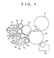
- Fig. 4 shows an example of a conventional intaglio printing press applied to printing of banknotes or securities (see, for example, Japanese Unexamined Patent Publication No. 2-42070).
- a plate cylinder 112 having an intaglio plate mounted on an outer peripheral surface thereof is contacted with an impression cylinder 111.
- an ink collecting cylinder 113 having rubber blankets mounted on an outer peripheral surface thereof is opposed in contact with the plate cylinder 112.
- three chablon rollers 114 are opposed in contact with the ink collecting cylinder 113 along a circumferential direction of the ink collecting cylinder 113.
- an ink fountain 117 filled with ordinary ink for printing of a main pattern is opposed in contact with the chablon roller via an ink fountain roller 116 and intermediate rollers 115.
- a chablon roller 118 is also opposed in contact therewith.
- an ink fountain 121 filled with special ink, such as OVI (Optical Variable Ink) for printing of a pattern for forgery prevention is opposed in contact with the chablon roller 118 via an ink fountain roller 120 and intermediate rollers 119.
- a wiping roller 122 is disposed, in contact with the plate cylinder 112, for removing surplus ink adhering to the surface of the intaglio plate.
- the wiping roller 122 is immersed in a solvent stored in a wiping tank 123.
- each ordinary ink is supplied from inside the ink fountain 117 to the chablon roller 114 via the ink fountain roller 116 and the intermediate rollers 115, each such ink is fed to the ink collecting cylinder 113, and then to the intaglio plate of the plate cylinder 112.
- special ink is supplied from inside the ink fountain 121 to the chablon roller 118 via the ink fountain roller 120 and the intermediate rollers 119, the special ink is directly fed to the intaglio plate of the plate cylinder 112.
- the inks supplied to the intaglio plate of the plate cylinder 112 have their surplus amounts removed by the wiping roller 118.
- the remaining inks on the intaglio plate of the plate cylinder 112 are transferred to a sheet passed on to the impression cylinder 111 to perform printing.
- EP-A-0 563 007 discloses an intaglio printing press as defined in the preamble portion of Claim 1 of the present application.
- GB-A-511 049 and NL-A-78 12 603 disclose rotary screens in connection with intaglio printing presses. However, these documents neither teach nor suggest means for preventing the rotary screen from falling into a groove.
- the present invention has been accomplished in view of the above-described problems. It is an object of the invention to provide an intaglio printing press which can use special ink with high efficiency.
- the present invention claims an intaglio printing press including all features of claim 1.
- the second ink supply means contacted with the plate cylinder and adapted to supply ink to the intaglio plate has the rotary screen.
- special ink which is expensive and poor in transfer characteristics, can be supplied with high efficiency to the intaglio plate of the plate cylinder, if it is supplied by unit of the rotary screen.
- deterioration of printing quality can be prevented, and an increase in the printing cost can be suppressed.
- said rotary screen may be composed of a cylindrical hollow roller supported rotatably and having a small hole formed therein; an ink feed means for feeding ink to an inner peripheral surface of said hollow roller; and a squeegee, disposed inside said hollow roller, for delivering the ink, which has been fed by said ink feed means, through the small hole of said hollow roller.
- said second ink supply means has the rotary screen, and a rubber roller contacted with said hollow roller of said rotary screen and said intaglio plate of said plate cylinder.
- the rubber roller has a groove in an outer peripheral portion thereof in contact with an ink portion transferred to said intaglio plate of said plate cylinder.
- support portions for constantly supporting said squeegee of said rotary screen via said hollow roller are provided on said rubber roller.
- the ink supplied by said second ink supply means may be OVI (Optical Variable Ink).
- Fig. 1 is a schematic constitution drawing of its essential part.
- Fig. 2 is a schematic structural drawing of an interior of a rotary screen in Fig. 1.
- Fig. 3 is a plan view of a rubber roller in Fig. 1.
- the invention is not restricted to this embodiment.
- a sheet feeder 10 stacked with sheets 100 communicates with a feedboard 11, which receives the sheets 100 fed one by one from an upper layer of a sheet stack by a sucker mechanism of the sheet feeder 10, and performs registration for printing.
- a swing arm shaft pregripper 12 is disposed for gripping the sheet 100 on the feedboard 11 and making a swing motion.
- the swing arm shaft pregripper 12 communicates, via a transfer cylinder 13, with an impression cylinder 14, which has a plurality of (three in the present embodiment) grippers 14a disposed with equal spacing in a circumferential direction of the impression cylinder 14.
- the transfer cylinder 13 is provided with grippers similar to the grippers of the impression cylinder 14, so that the sheet 100 gripped from the swing arm shaft pregripper 12 can be passed on to the gripper of the impression cylinder 14.
- a plate cylinder 15 which can have a plurality of intaglio plates mounted along a circumferential direction of the plate cylinder 15, is opposed in contact with the impression cylinder 14.
- an ink collecting cylinder 16 which can have a plurality of rubber blankets mounted along a circumferential direction of the ink collecting cylinder 16, is opposed in contact with the intaglio plates.
- a plurality of (four in the present embodiment) chablon rollers 17 are opposed in contact with, and circumferentially of, the ink collecting cylinder 16.
- an ink fountain 20 filled with ordinary ink for printing of a main pattern is opposed in contact with the chablon roller via an ink fountain roller 19 and intermediate rollers 18.
- the chablon rollers 17, intermediate rollers 18, ink fountain rollers 19, and ink fountain 20 constitute a first ink supply means according to the present embodiment.
- a rotary screen 22 filled inside with special ink such as OVI (Optical Variable Ink) for printing of a pattern for forgery prevention is opposed in contact with the plate cylinder 15 via a rubber roller 21.
- the rotary screen 22 has a structure as shown in Fig. 2.
- the rotary screen 22 comprises a hollow roller 22c, which is a cylinder of a thin screen (a screen of stainless steel, nickel or the like) having an etching of a small hole corresponding to a pattern.
- the hollow roller 22c is rotatably mounted so that an ink fountain 22a, which is an ink feed means fixed to a frame, and a squeegee 22b will be positioned inside the hollow roller 22c.
- the special ink in the ink fountain 22a is delivered by the squeegee 22b through the small hole of the hollow roller 22c.
- the special ink can be supplied to the intaglio plate of the plate cylinder 15 via a printing pattern 21b (see Fig. 3) of a blanket 21a of the rubber roller 21.
- the rotary screen 22 can directly feed special ink in a constant amount, at a time, in a predetermined pattern.
- Such rubber roller 21 and rotary screen 22 constitute a second ink supply means according to the present embodiment.
- the rubber roller 21 has a groove 21c formed in the blanket 21a on the outer periphery thereof which is in contact with an ordinary ink portion transferred to the intaglio plate of the plate cylinder 15, as shown in Fig. 3.
- the groove 21c of the blanket 21a of the rubber roller 21 is formed over the entire widthwise length of the blanket 21a, the squeegee 22b of the rotary screen 22 falls into the groove 21c together with the hollow roller 22c.
- a support portion 21d for constantly supporting both end sides of the squeegee 22b via the hollow roller 22c is formed on each of both end sides, in the width direction, of the blanket 21a of the rubber roller 21.
- a wiping roller 23 is contacted with the intaglio plate on the plate cylinder 15.
- the wiping roller 23 is immersed in a solvent stored in a wiping tank 24.
- a delivery cylinder 25 is opposed in contact therewith. Between a sprocket coaxial with the delivery cylinder 25 and a sprocket (not shown), a pair of delivery chains 26 are looped. The delivery chains 26 are provided with delivery grippers (not shown) which grip the sheet 100 from the gripper 14a of the impression cylinder 14.
- the foregoing intaglio printing press is operated in the following manner:
- the sheets 100 are fed, one by one, from the sheet feeder 10 onto the feedboard 11.
- the sheet 100 is passed from the swing arm shaft pregripper 12 to the transfer cylinder 13, and then to the gripper 14a of the impression cylinder 14, whereupon the sheet 100 is further transported.
- each ordinary ink is supplied from inside the ink fountain 20 to the chablon roller 17 via the ink fountain roller 19 and the intermediate rollers 18, and further to the ink collecting cylinder 16.
- the respective ordinary inks are supplied to the intaglio plates of the plate cylinder 15.
- the rotary screen 22 directly feeds special ink in a constant amount, at a time, in a predetermined pattern.
- special ink with poor transfer characteristics can be supplied efficiently to the intaglio plate of the plate cylinder 15.
- deterioration of printing quality can be prevented, and increase in the printing cost can be suppressed.
Abstract
Description
- The present invention relates to an intaglio printing press, and especially, one useful when applied to printing of banknotes or securities.
- Fig. 4 shows an example of a conventional intaglio printing press applied to printing of banknotes or securities (see, for example, Japanese Unexamined Patent Publication No. 2-42070). As shown in Fig. 4, a
plate cylinder 112 having an intaglio plate mounted on an outer peripheral surface thereof is contacted with animpression cylinder 111. To theplate cylinder 112, anink collecting cylinder 113 having rubber blankets mounted on an outer peripheral surface thereof is opposed in contact with theplate cylinder 112. To theink collecting cylinder 113, threechablon rollers 114 are opposed in contact with theink collecting cylinder 113 along a circumferential direction of theink collecting cylinder 113. To each of thesechablon rollers 114, anink fountain 117 filled with ordinary ink for printing of a main pattern is opposed in contact with the chablon roller via anink fountain roller 116 andintermediate rollers 115. To theplate cylinder 112, achablon roller 118 is also opposed in contact therewith. To thischablon roller 118, anink fountain 121 filled with special ink, such as OVI (Optical Variable Ink), for printing of a pattern for forgery prevention is opposed in contact with thechablon roller 118 via anink fountain roller 120 andintermediate rollers 119. Opposite theplate cylinder 112 and downstream from theink collecting cylinder 113, awiping roller 122 is disposed, in contact with theplate cylinder 112, for removing surplus ink adhering to the surface of the intaglio plate. Thewiping roller 122 is immersed in a solvent stored in awiping tank 123. - The foregoing conventional intaglio printing press is operated in the following manner:
- When each ordinary ink is supplied from inside the
ink fountain 117 to thechablon roller 114 via theink fountain roller 116 and theintermediate rollers 115, each such ink is fed to theink collecting cylinder 113, and then to the intaglio plate of theplate cylinder 112. On the other hand, when special ink is supplied from inside theink fountain 121 to thechablon roller 118 via theink fountain roller 120 and theintermediate rollers 119, the special ink is directly fed to the intaglio plate of theplate cylinder 112. The inks supplied to the intaglio plate of theplate cylinder 112 have their surplus amounts removed by thewiping roller 118. The remaining inks on the intaglio plate of theplate cylinder 112 are transferred to a sheet passed on to theimpression cylinder 111 to perform printing. - Special ink, such as the aforementioned OVI, is expensive and has poor transfer characteristics. Thus, when it is supplied from the
ink fountain 121 to the intaglio plate of theplate cylinder 112 via theink fountain roller 120, theintermediate rollers 119, and thechablon roller 118, its loss increases, thereby deteriorating printing quality, and making the printing cost very high. Methods for minimizing the use of theintermediate rollers 119, etc. have been worked out, but have been unsuccessful in obtaining satisfactory results. - EP-A-0 563 007 discloses an intaglio printing press as defined in the preamble portion of Claim 1 of the present application.
- GB-A-511 049 and NL-A-78 12 603 disclose rotary screens in connection with intaglio printing presses. However, these documents neither teach nor suggest means for preventing the rotary screen from falling into a groove.
- The present invention has been accomplished in view of the above-described problems. It is an object of the invention to provide an intaglio printing press which can use special ink with high efficiency.
- To attain the above object, the present invention claims an intaglio printing press including all features of claim 1.
- According to the intaglio printing press of the present invention, as described above, the second ink supply means contacted with the plate cylinder and adapted to supply ink to the intaglio plate has the rotary screen. Even special ink, which is expensive and poor in transfer characteristics, can be supplied with high efficiency to the intaglio plate of the plate cylinder, if it is supplied by unit of the rotary screen. Thus, even when special ink, expensive and poor in transfer characteristics, is used, deterioration of printing quality can be prevented, and an increase in the printing cost can be suppressed.
- In the foregoing intaglio-printing press, said rotary screen may be composed of a cylindrical hollow roller supported rotatably and having a small hole formed therein; an ink feed means for feeding ink to an inner peripheral surface of said hollow roller; and a squeegee, disposed inside said hollow roller, for delivering the ink, which has been fed by said ink feed means, through the small hole of said hollow roller. In the intaglio printing press, said second ink supply means has the rotary screen, and a rubber roller contacted with said hollow roller of said rotary screen and said intaglio plate of said plate cylinder.
- In the intaglio printing press, the rubber roller has a groove in an outer peripheral portion thereof in contact with an ink portion transferred to said intaglio plate of said plate cylinder.
- In the intaglio printing press, support portions for constantly supporting said squeegee of said rotary screen via said hollow roller are provided on said rubber roller.
- In the intaglio printing press, the ink supplied by said second ink supply means may be OVI (Optical Variable Ink).
- The present invention will become more fully understood from the detailed description given hereinbelow and the accompanying drawings which are given by way of illustration only, and thus are not limitative of the present invention, and wherein:
- Fig. 1 is a schematic constitution drawing of an essential part of an embodiment of an intaglio printing press according to the present invention;
- Fig. 2 is a schematic structural drawing of an interior of a rotary screen in Fig. 1;
- Fig. 3 is a plan view of a rubber roller in Fig. 1; and
- Fig. 4 is a schematic structural drawing of an essential part of an example of a conventional intaglio printing press.
-
- An embodiment of an intaglio printing press according to the present invention will now be described with reference to Figs. 1 to 3. Fig. 1 is a schematic constitution drawing of its essential part. Fig. 2 is a schematic structural drawing of an interior of a rotary screen in Fig. 1. Fig. 3 is a plan view of a rubber roller in Fig. 1. However, it should be understood that the invention is not restricted to this embodiment.
- As shown in Fig. 1, a
sheet feeder 10 stacked withsheets 100 communicates with afeedboard 11, which receives thesheets 100 fed one by one from an upper layer of a sheet stack by a sucker mechanism of thesheet feeder 10, and performs registration for printing. On thefeedboard 11, a swingarm shaft pregripper 12 is disposed for gripping thesheet 100 on thefeedboard 11 and making a swing motion. The swingarm shaft pregripper 12 communicates, via atransfer cylinder 13, with animpression cylinder 14, which has a plurality of (three in the present embodiment)grippers 14a disposed with equal spacing in a circumferential direction of theimpression cylinder 14. Thetransfer cylinder 13 is provided with grippers similar to the grippers of theimpression cylinder 14, so that thesheet 100 gripped from the swingarm shaft pregripper 12 can be passed on to the gripper of theimpression cylinder 14. - To the
impression cylinder 14, aplate cylinder 15, which can have a plurality of intaglio plates mounted along a circumferential direction of theplate cylinder 15, is opposed in contact with theimpression cylinder 14. To the intaglio plates of theplate cylinder 15, anink collecting cylinder 16, which can have a plurality of rubber blankets mounted along a circumferential direction of theink collecting cylinder 16, is opposed in contact with the intaglio plates. To theink collecting cylinder 16, a plurality of (four in the present embodiment)chablon rollers 17 are opposed in contact with, and circumferentially of, theink collecting cylinder 16. To each of thesechablon rollers 17, anink fountain 20 filled with ordinary ink for printing of a main pattern is opposed in contact with the chablon roller via anink fountain roller 19 andintermediate rollers 18. Thechablon rollers 17,intermediate rollers 18,ink fountain rollers 19, andink fountain 20 constitute a first ink supply means according to the present embodiment. - To the
plate cylinder 15, arotary screen 22 filled inside with special ink such as OVI (Optical Variable Ink) for printing of a pattern for forgery prevention is opposed in contact with theplate cylinder 15 via arubber roller 21. Therotary screen 22 has a structure as shown in Fig. 2. As shown in Fig. 2, therotary screen 22 comprises ahollow roller 22c, which is a cylinder of a thin screen (a screen of stainless steel, nickel or the like) having an etching of a small hole corresponding to a pattern. Thehollow roller 22c is rotatably mounted so that anink fountain 22a, which is an ink feed means fixed to a frame, and asqueegee 22b will be positioned inside thehollow roller 22c. With thehollow roller 22c being rotated, special ink in theink fountain 22a is delivered by thesqueegee 22b through the small hole of thehollow roller 22c. By this measure, the special ink can be supplied to the intaglio plate of theplate cylinder 15 via aprinting pattern 21b (see Fig. 3) of a blanket 21a of therubber roller 21. In other words, therotary screen 22 can directly feed special ink in a constant amount, at a time, in a predetermined pattern.Such rubber roller 21 androtary screen 22 constitute a second ink supply means according to the present embodiment. - To prevent ordinary ink, transferred from the
ink collecting cylinder 16 to the intaglio plate of theplate cylinder 15, from migrating to therotary screen 22, therubber roller 21 has agroove 21c formed in the blanket 21a on the outer periphery thereof which is in contact with an ordinary ink portion transferred to the intaglio plate of theplate cylinder 15, as shown in Fig. 3. When thegroove 21c of the blanket 21a of therubber roller 21 is formed over the entire widthwise length of the blanket 21a, thesqueegee 22b of therotary screen 22 falls into thegroove 21c together with thehollow roller 22c. To prevent the fall of thesqueegee 22b and thehollow roller 22c of therotary screen 22 into thegroove 21c of the blanket 21a of therubber roller 21, asupport portion 21d for constantly supporting both end sides of thesqueegee 22b via thehollow roller 22c is formed on each of both end sides, in the width direction, of the blanket 21a of therubber roller 21. - As shown in Fig. 1, a wiping
roller 23 is contacted with the intaglio plate on theplate cylinder 15. The wipingroller 23 is immersed in a solvent stored in awiping tank 24. - To the
impression cylinder 14, adelivery cylinder 25 is opposed in contact therewith. Between a sprocket coaxial with thedelivery cylinder 25 and a sprocket (not shown), a pair ofdelivery chains 26 are looped. Thedelivery chains 26 are provided with delivery grippers (not shown) which grip thesheet 100 from thegripper 14a of theimpression cylinder 14. - The foregoing intaglio printing press is operated in the following manner: The
sheets 100 are fed, one by one, from thesheet feeder 10 onto thefeedboard 11. Thesheet 100 is passed from the swingarm shaft pregripper 12 to thetransfer cylinder 13, and then to thegripper 14a of theimpression cylinder 14, whereupon thesheet 100 is further transported. Separately, each ordinary ink is supplied from inside theink fountain 20 to thechablon roller 17 via theink fountain roller 19 and theintermediate rollers 18, and further to theink collecting cylinder 16. Then, the respective ordinary inks are supplied to the intaglio plates of theplate cylinder 15. Simultaneously, special ink is directly supplied, in a constant amount at a time, in a predetermined pattern, from inside therotary screen 22 to the intaglio plates of theplate cylinder 15 via therubber roller 21. After surplus inks are removed by the wipingroller 23, the remaining inks on the intaglio plates are transferred onto thesheet 100 accepted by theimpression cylinder 14 for printing. The printedsheet 100 is carried and discharged by thedelivery chains 26 via thedelivery cylinder 25. - As described previously, the
rotary screen 22 directly feeds special ink in a constant amount, at a time, in a predetermined pattern. Thus, special ink with poor transfer characteristics can be supplied efficiently to the intaglio plate of theplate cylinder 15. Thus, even when special ink, expensive and poor in transfer characteristics, is used, deterioration of printing quality can be prevented, and increase in the printing cost can be suppressed. - This invention being thus described, it will be obvious that the same may be varied in many ways. Such variations are not to be regarded as a departure from the scope of the invention, and all such modifications as would be obvious to one skilled in the art are intended to be included within the scope of the following claims.
Claims (6)
- An intaglio printing press including a plate cylinder (15) having an intaglio plate mounted on a circumferential surface of the plate cylinder (15), an impression cylinder (14) contacted with said plate cylinder (15), an ink collecting cylinder (16) contacted with said plate cylinder (15) and having a blanket mounted on a circumferential surface of the ink collecting cylinder (16), a first ink supply means (17-20) for supplying ink to said blanket of said ink collecting cylinder (16), a second ink supply means (21, 22) contacted with said plate cylinder (15), for supplying ink to said intaglio plate; and a wiping roller (23) contacted with said plate cylinder (15),
characterized in that
said second ink supply means (21, 22) comprises a rotary screen (22), and an intermediate rubber roller (21) in contact with said rotary screen (22) and said intaglio plate of said plate cylinder (15);
said intermediate rubber roller (21) has on an outer periphery a groove (21c) and a printing pattern (21b) for transferring ink to said intaglio plate of said plate cylinder (15); and
a support portion (21d) for preventing said rotary screen (22) from falling in said groove (21a) of said intermediate rubber roller (21) is provided on said intermediate rubber roller (21). - The intaglio printing press as claimed in claim 1, characterized in that said rotary screen (22) comprises:a cylindrical hollow roller (22c) supported rotatably and having a small hole formed therein;an ink feed means (22a) for feeding ink to an inner peripheral surface of said hollow roller (22); anda squeegee (22b), disposed inside said hollow roller (22c), for delivering the ink, which has been fed by said ink feed means (22a), through the small hole of said hollow roller (22).
- The intaglio printing press as claimed in claim 2, characterized in that said intermediate rubber roller (21) is disposed such that said intermediate rubber roller (21) comes onto contact with said hollow roller (22c) and said intaglio plate of said plate cylinder (15).
- The intaglio printing press as claimed in claim 1, characterized in that said groove (21c) of said intermediate rubber roller (21) is provided at a position corresponding to a portion of said intaglio plate of said plate cylinder (15) which portion receives ink transferred from said first ink supply means (17-20).
- The intaglio printing press as claimed in claim 2, characterized in that said support portion (21d) is provided on said intermediate rubber roller (21) in such a manner that said support portion (21d) always supports said squeegee (22b) via said hollow roller (22c).
- The intaglio printing press as claimed in claim 1, characterized in that said second ink supply means (21), (22) is adapted to supply optical variable ink (OVI).
Applications Claiming Priority (4)
| Application Number | Priority Date | Filing Date | Title |
|---|---|---|---|
| JP23510298 | 1998-08-21 | ||
| JP23510298 | 1998-08-21 | ||
| JP20725999 | 1999-07-22 | ||
| JP20725999A JP4226155B2 (en) | 1998-08-21 | 1999-07-22 | Intaglio printing machine |
Publications (3)
| Publication Number | Publication Date |
|---|---|
| EP0982131A2 EP0982131A2 (en) | 2000-03-01 |
| EP0982131A3 EP0982131A3 (en) | 2000-09-20 |
| EP0982131B1 true EP0982131B1 (en) | 2003-06-04 |
Family
ID=26516149
Family Applications (1)
| Application Number | Title | Priority Date | Filing Date |
|---|---|---|---|
| EP99250278A Revoked EP0982131B1 (en) | 1998-08-21 | 1999-08-17 | Ink unit in an intaglio printing press |
Country Status (6)
| Country | Link |
|---|---|
| US (1) | US6202554B1 (en) |
| EP (1) | EP0982131B1 (en) |
| JP (1) | JP4226155B2 (en) |
| AT (1) | ATE242123T1 (en) |
| DE (1) | DE69908514T2 (en) |
| ES (1) | ES2204063T3 (en) |
Families Citing this family (15)
| Publication number | Priority date | Publication date | Assignee | Title |
|---|---|---|---|---|
| US6779445B2 (en) | 2000-01-25 | 2004-08-24 | Koenig & Bauer Aktiengesellschaft | Intaglio printer |
| JP4128866B2 (en) * | 2002-12-26 | 2008-07-30 | 株式会社小森コーポレーション | Ink supply amount control method and apparatus for printing press |
| EP1445098A1 (en) * | 2003-02-04 | 2004-08-11 | Kba-Giori S.A. | Blanket cylinder for an intaglio printing machine |
| RU2490136C2 (en) * | 2004-01-15 | 2013-08-20 | КБА-НотаСис СА | System of ink application for gravure printing machine |
| EP1602483A1 (en) * | 2004-06-03 | 2005-12-07 | Kba-Giori S.A. | Intaglio printing machine and process |
| EP1602482A1 (en) * | 2004-06-03 | 2005-12-07 | Kba-Giori S.A. | Intaglio printing machine with antishock cylinder arrangement |
| EP1842665A1 (en) * | 2006-04-04 | 2007-10-10 | Kba-Giori S.A. | Process for producing security papers, intaglio printing press for implementing said process, and security paper produced according to said process |
| JP4829033B2 (en) * | 2006-08-09 | 2011-11-30 | 株式会社小森コーポレーション | Information recording medium supply device |
| DE102006048329A1 (en) * | 2006-10-12 | 2008-04-17 | Man Roland Druckmaschinen Ag | Paint dosing device for an inking unit |
| JP5069896B2 (en) † | 2006-10-23 | 2012-11-07 | 株式会社小森コーポレーション | Liquid supply device |
| JP5019215B2 (en) * | 2007-08-30 | 2012-09-05 | 独立行政法人 国立印刷局 | Intaglio printing machine |
| JP5022891B2 (en) * | 2007-12-28 | 2012-09-12 | 株式会社小森コーポレーション | Liquid application machine |
| CN103282206B (en) * | 2011-12-23 | 2015-01-21 | 中国人民银行印制科学技术研究所 | Method and device for ink transfer and feed, and printing apparatus having the device |
| EP2961615B8 (en) * | 2013-03-01 | 2024-02-14 | Sicpa Holding Sa | Intaglio printing |
| CN114132100B (en) * | 2021-11-19 | 2024-03-29 | 云南嘉科包装科技股份有限公司 | Gravure raised character ink printing process |
Family Cites Families (16)
| Publication number | Priority date | Publication date | Assignee | Title |
|---|---|---|---|---|
| DE440444C (en) * | 1924-12-03 | 1927-02-07 | Arthur Seidemann | Inking unit for flat printer |
| GB511049A (en) * | 1938-02-11 | 1939-08-11 | Max Friedrich Scheffler | Method of and apparatus for intaglio printing in one or more colours |
| DE1230437B (en) * | 1960-05-16 | 1966-12-15 | Gualtiero Giori | Multi-color steel engraving printing machine with an engraved printing plate arranged on a rotating forme cylinder and several partial image cylinders |
| CH477293A (en) * | 1967-12-19 | 1969-08-31 | Giori Gualtiero | Multi-color steel engraving printing machine for the production of notes of value, in particular banknotes |
| US4056056A (en) * | 1973-03-21 | 1977-11-01 | De La Rue Giori S.A. | Rotary printing press |
| US4103615A (en) * | 1976-01-14 | 1978-08-01 | Sir James Farmer Norton & Co., Limited | Vertical rotary screen printing machine and ink supply therefore |
| NL7812603A (en) * | 1978-12-28 | 1980-07-01 | Thomassen & Drijver | Printing ink or paint feed mechanism - uses perforated feed roller resting against roller with deformable surface located against impression cylinder |
| DE3109964A1 (en) * | 1981-03-14 | 1982-12-02 | Koenig & Bauer AG, 8700 Würzburg | "COLLECTIVE PRINTING MACHINE PRINTER FOR SECURITIES PRINTING" |
| AU550695B2 (en) * | 1982-04-07 | 1986-03-27 | De La Rue Giori S.A. | Copperplate engraving machine for paper currency |
| JPS603375U (en) * | 1983-06-22 | 1985-01-11 | ハウス食品工業株式会社 | Three-way valve cleaning piping |
| JPS6161856A (en) * | 1984-09-03 | 1986-03-29 | Komori Printing Mach Co Ltd | Intaglio printing machine |
| EP0406157B1 (en) * | 1989-06-29 | 1994-05-18 | De La Rue Giori S.A. | Platen printing machine for printing security paper |
| JPH0437545A (en) * | 1990-06-01 | 1992-02-07 | Komori Corp | Cylinder setting control of intaglio printer and its device |
| JP3061931B2 (en) * | 1991-05-14 | 2000-07-10 | 理想科学工業株式会社 | Ink supply control device for stencil printing machine |
| EP0563007B1 (en) * | 1992-03-26 | 1996-07-10 | De La Rue Giori S.A. | Intaglio printing machine |
| DE69600551T2 (en) * | 1995-02-28 | 1999-04-29 | Riso Kagaku Corp | Stencil printing process and emulsion ink for stencil printing |
-
1999
- 1999-07-22 JP JP20725999A patent/JP4226155B2/en not_active Expired - Fee Related
- 1999-08-17 AT AT99250278T patent/ATE242123T1/en not_active IP Right Cessation
- 1999-08-17 EP EP99250278A patent/EP0982131B1/en not_active Revoked
- 1999-08-17 DE DE69908514T patent/DE69908514T2/en not_active Revoked
- 1999-08-17 ES ES99250278T patent/ES2204063T3/en not_active Expired - Lifetime
- 1999-08-18 US US09/376,369 patent/US6202554B1/en not_active Expired - Fee Related
Also Published As
| Publication number | Publication date |
|---|---|
| JP2000127351A (en) | 2000-05-09 |
| DE69908514D1 (en) | 2003-07-10 |
| ATE242123T1 (en) | 2003-06-15 |
| EP0982131A3 (en) | 2000-09-20 |
| JP4226155B2 (en) | 2009-02-18 |
| ES2204063T3 (en) | 2004-04-16 |
| US6202554B1 (en) | 2001-03-20 |
| EP0982131A2 (en) | 2000-03-01 |
| DE69908514T2 (en) | 2004-04-29 |
Similar Documents
| Publication | Publication Date | Title |
|---|---|---|
| EP0982131B1 (en) | Ink unit in an intaglio printing press | |
| EP1867477B1 (en) | A printing press with an intaglio printing unit, a stencil printing unit and a drying device | |
| JP5837030B2 (en) | An intaglio printing press system for intaglio printing on the front-back side of a sheet of paper to produce banknotes and similar securities | |
| US6050188A (en) | Sheet-fed rotary press | |
| US8925453B2 (en) | Intaglio printing press | |
| EP0982125B1 (en) | Multicolour intaglio printing press | |
| KR101054513B1 (en) | Driving of ink attachment unit of intaglio printing press | |
| EP2468506B1 (en) | Identification mark printing machine | |
| JPH0241413B2 (en) | ||
| CZ14898A3 (en) | Offset web-fed rotary for printing sheets | |
| US4942813A (en) | Method and apparatus for dry offset intaglio printing | |
| EP1088657A1 (en) | Printing machine | |
| EP0906826A2 (en) | Perfecting sheet-fed rotary press | |
| US1459312A (en) | Printing press | |
| EP0275025A2 (en) | Inking device for printing apparatus | |
| US6546862B1 (en) | Method and device for producing a multicolor print | |
| JPH11188852A (en) | Intaglio printing machine | |
| EP0420234A2 (en) | Multicolor printing press | |
| JPH10278220A (en) | Sheet-feed rotary press | |
| JPH0364309B2 (en) | ||
| JPH0314355Y2 (en) | ||
| JPS58173658A (en) | Printing machine for both sides of paper | |
| JPH01288444A (en) | Printer | |
| GB2366242A (en) | Lithographic printing machine with interchangeable cartridge | |
| JPH028590B2 (en) |
Legal Events
| Date | Code | Title | Description |
|---|---|---|---|
| PUAI | Public reference made under article 153(3) epc to a published international application that has entered the european phase |
Free format text: ORIGINAL CODE: 0009012 |
|
| AK | Designated contracting states |
Kind code of ref document: A2 Designated state(s): AT BE CH CY DE DK ES FI FR GB GR IE IT LI LU MC NL PT SE |
|
| AX | Request for extension of the european patent |
Free format text: AL;LT;LV;MK;RO;SI |
|
| PUAL | Search report despatched |
Free format text: ORIGINAL CODE: 0009013 |
|
| AK | Designated contracting states |
Kind code of ref document: A3 Designated state(s): AT BE CH CY DE DK ES FI FR GB GR IE IT LI LU MC NL PT SE |
|
| AX | Request for extension of the european patent |
Free format text: AL;LT;LV;MK;RO;SI |
|
| RIC1 | Information provided on ipc code assigned before grant |
Free format text: 7B 41F 31/22 A, 7B 41F 9/02 B, 7B 41F 9/06 B |
|
| 17P | Request for examination filed |
Effective date: 20010302 |
|
| AKX | Designation fees paid |
Free format text: AT BE CH CY DE DK ES FI FR GB GR IE IT LI LU MC NL PT SE |
|
| 17Q | First examination report despatched |
Effective date: 20010612 |
|
| GRAH | Despatch of communication of intention to grant a patent |
Free format text: ORIGINAL CODE: EPIDOS IGRA |
|
| GRAH | Despatch of communication of intention to grant a patent |
Free format text: ORIGINAL CODE: EPIDOS IGRA |
|
| GRAA | (expected) grant |
Free format text: ORIGINAL CODE: 0009210 |
|
| AK | Designated contracting states |
Designated state(s): AT BE CH CY DE DK ES FI FR GB GR IE IT LI LU MC NL PT SE |
|
| PG25 | Lapsed in a contracting state [announced via postgrant information from national office to epo] |
Ref country code: FI Free format text: LAPSE BECAUSE OF FAILURE TO SUBMIT A TRANSLATION OF THE DESCRIPTION OR TO PAY THE FEE WITHIN THE PRESCRIBED TIME-LIMIT Effective date: 20030604 Ref country code: BE Free format text: LAPSE BECAUSE OF FAILURE TO SUBMIT A TRANSLATION OF THE DESCRIPTION OR TO PAY THE FEE WITHIN THE PRESCRIBED TIME-LIMIT Effective date: 20030604 Ref country code: AT Free format text: LAPSE BECAUSE OF FAILURE TO SUBMIT A TRANSLATION OF THE DESCRIPTION OR TO PAY THE FEE WITHIN THE PRESCRIBED TIME-LIMIT Effective date: 20030604 |
|
| REG | Reference to a national code |
Ref country code: GB Ref legal event code: FG4D |
|
| REG | Reference to a national code |
Ref country code: SE Ref legal event code: TRGR |
|
| REG | Reference to a national code |
Ref country code: CH Ref legal event code: EP |
|
| REG | Reference to a national code |
Ref country code: IE Ref legal event code: FG4D |
|
| REF | Corresponds to: |
Ref document number: 69908514 Country of ref document: DE Date of ref document: 20030710 Kind code of ref document: P |
|
| PG25 | Lapsed in a contracting state [announced via postgrant information from national office to epo] |
Ref country code: LU Free format text: LAPSE BECAUSE OF NON-PAYMENT OF DUE FEES Effective date: 20030817 Ref country code: CY Free format text: LAPSE BECAUSE OF FAILURE TO SUBMIT A TRANSLATION OF THE DESCRIPTION OR TO PAY THE FEE WITHIN THE PRESCRIBED TIME-LIMIT Effective date: 20030817 |
|
| PG25 | Lapsed in a contracting state [announced via postgrant information from national office to epo] |
Ref country code: IE Free format text: LAPSE BECAUSE OF NON-PAYMENT OF DUE FEES Effective date: 20030818 |
|
| REG | Reference to a national code |
Ref country code: CH Ref legal event code: NV Representative=s name: R. A. EGLI & CO. PATENTANWAELTE |
|
| PG25 | Lapsed in a contracting state [announced via postgrant information from national office to epo] |
Ref country code: MC Free format text: LAPSE BECAUSE OF NON-PAYMENT OF DUE FEES Effective date: 20030831 |
|
| PG25 | Lapsed in a contracting state [announced via postgrant information from national office to epo] |
Ref country code: PT Free format text: LAPSE BECAUSE OF FAILURE TO SUBMIT A TRANSLATION OF THE DESCRIPTION OR TO PAY THE FEE WITHIN THE PRESCRIBED TIME-LIMIT Effective date: 20030904 Ref country code: GR Free format text: LAPSE BECAUSE OF FAILURE TO SUBMIT A TRANSLATION OF THE DESCRIPTION OR TO PAY THE FEE WITHIN THE PRESCRIBED TIME-LIMIT Effective date: 20030904 Ref country code: DK Free format text: LAPSE BECAUSE OF FAILURE TO SUBMIT A TRANSLATION OF THE DESCRIPTION OR TO PAY THE FEE WITHIN THE PRESCRIBED TIME-LIMIT Effective date: 20030904 |
|
| PLBQ | Unpublished change to opponent data |
Free format text: ORIGINAL CODE: EPIDOS OPPO |
|
| PLBI | Opposition filed |
Free format text: ORIGINAL CODE: 0009260 |
|
| ET | Fr: translation filed | ||
| PLAX | Notice of opposition and request to file observation + time limit sent |
Free format text: ORIGINAL CODE: EPIDOSNOBS2 |
|
| REG | Reference to a national code |
Ref country code: ES Ref legal event code: FG2A Ref document number: 2204063 Country of ref document: ES Kind code of ref document: T3 |
|
| 26 | Opposition filed |
Opponent name: KBA-GIORI S.A. Effective date: 20040302 |
|
| REG | Reference to a national code |
Ref country code: IE Ref legal event code: MM4A |
|
| NLR1 | Nl: opposition has been filed with the epo |
Opponent name: KBA-GIORI S.A. |
|
| PLBB | Reply of patent proprietor to notice(s) of opposition received |
Free format text: ORIGINAL CODE: EPIDOSNOBS3 |
|
| PLAY | Examination report in opposition despatched + time limit |
Free format text: ORIGINAL CODE: EPIDOSNORE2 |
|
| PLBC | Reply to examination report in opposition received |
Free format text: ORIGINAL CODE: EPIDOSNORE3 |
|
| APBP | Date of receipt of notice of appeal recorded |
Free format text: ORIGINAL CODE: EPIDOSNNOA2O |
|
| APAH | Appeal reference modified |
Free format text: ORIGINAL CODE: EPIDOSCREFNO |
|
| APBQ | Date of receipt of statement of grounds of appeal recorded |
Free format text: ORIGINAL CODE: EPIDOSNNOA3O |
|
| PGFP | Annual fee paid to national office [announced via postgrant information from national office to epo] |
Ref country code: NL Payment date: 20080815 Year of fee payment: 10 Ref country code: ES Payment date: 20080826 Year of fee payment: 10 |
|
| PGFP | Annual fee paid to national office [announced via postgrant information from national office to epo] |
Ref country code: IT Payment date: 20080827 Year of fee payment: 10 Ref country code: FR Payment date: 20080818 Year of fee payment: 10 |
|
| PGFP | Annual fee paid to national office [announced via postgrant information from national office to epo] |
Ref country code: GB Payment date: 20080827 Year of fee payment: 10 |
|
| PGFP | Annual fee paid to national office [announced via postgrant information from national office to epo] |
Ref country code: SE Payment date: 20080807 Year of fee payment: 10 |
|
| PLAB | Opposition data, opponent's data or that of the opponent's representative modified |
Free format text: ORIGINAL CODE: 0009299OPPO |
|
| R26 | Opposition filed (corrected) |
Opponent name: KBA-GIORI S.A. Effective date: 20040302 |
|
| REG | Reference to a national code |
Ref country code: NL Ref legal event code: V1 Effective date: 20100301 |
|
| GBPC | Gb: european patent ceased through non-payment of renewal fee |
Effective date: 20090817 |
|
| APBU | Appeal procedure closed |
Free format text: ORIGINAL CODE: EPIDOSNNOA9O |
|
| REG | Reference to a national code |
Ref country code: FR Ref legal event code: ST Effective date: 20100430 |
|
| PLAB | Opposition data, opponent's data or that of the opponent's representative modified |
Free format text: ORIGINAL CODE: 0009299OPPO |
|
| R26 | Opposition filed (corrected) |
Opponent name: KBA-GIORI S.A. Effective date: 20040302 |
|
| PG25 | Lapsed in a contracting state [announced via postgrant information from national office to epo] |
Ref country code: NL Free format text: LAPSE BECAUSE OF NON-PAYMENT OF DUE FEES Effective date: 20100301 Ref country code: FR Free format text: LAPSE BECAUSE OF NON-PAYMENT OF DUE FEES Effective date: 20090831 |
|
| RDAF | Communication despatched that patent is revoked |
Free format text: ORIGINAL CODE: EPIDOSNREV1 |
|
| RDAG | Patent revoked |
Free format text: ORIGINAL CODE: 0009271 |
|
| STAA | Information on the status of an ep patent application or granted ep patent |
Free format text: STATUS: PATENT REVOKED |
|
| REG | Reference to a national code |
Ref country code: CH Ref legal event code: PL |
|
| 27W | Patent revoked |
Effective date: 20100511 |
|
| REG | Reference to a national code |
Ref country code: ES Ref legal event code: FD2A Effective date: 20090818 |
|
| PG25 | Lapsed in a contracting state [announced via postgrant information from national office to epo] |
Ref country code: LI Free format text: LAPSE BECAUSE OF THE APPLICANT RENOUNCES Effective date: 20030604 Ref country code: CH Free format text: LAPSE BECAUSE OF THE APPLICANT RENOUNCES Effective date: 20030604 |
|
| PGFP | Annual fee paid to national office [announced via postgrant information from national office to epo] |
Ref country code: CH Payment date: 20100812 Year of fee payment: 12 |
|
| PG25 | Lapsed in a contracting state [announced via postgrant information from national office to epo] |
Ref country code: GB Free format text: LAPSE BECAUSE OF NON-PAYMENT OF DUE FEES Effective date: 20090817 |
|
| PGFP | Annual fee paid to national office [announced via postgrant information from national office to epo] |
Ref country code: DE Payment date: 20100812 Year of fee payment: 12 |
|
| PG25 | Lapsed in a contracting state [announced via postgrant information from national office to epo] |
Ref country code: IT Free format text: LAPSE BECAUSE OF NON-PAYMENT OF DUE FEES Effective date: 20090817 |
|
| PG25 | Lapsed in a contracting state [announced via postgrant information from national office to epo] |
Ref country code: SE Free format text: LAPSE BECAUSE OF NON-PAYMENT OF DUE FEES Effective date: 20090818 |
|
| PG25 | Lapsed in a contracting state [announced via postgrant information from national office to epo] |
Ref country code: ES Free format text: LAPSE BECAUSE OF NON-PAYMENT OF DUE FEES Effective date: 20090818 |