EP0906826A2 - Perfecting sheet-fed rotary press - Google Patents
Perfecting sheet-fed rotary press Download PDFInfo
- Publication number
- EP0906826A2 EP0906826A2 EP98250349A EP98250349A EP0906826A2 EP 0906826 A2 EP0906826 A2 EP 0906826A2 EP 98250349 A EP98250349 A EP 98250349A EP 98250349 A EP98250349 A EP 98250349A EP 0906826 A2 EP0906826 A2 EP 0906826A2
- Authority
- EP
- European Patent Office
- Prior art keywords
- sheet
- cylinder
- cylinders
- impression
- impression cylinder
- Prior art date
- Legal status (The legal status is an assumption and is not a legal conclusion. Google has not performed a legal analysis and makes no representation as to the accuracy of the status listed.)
- Granted
Links
Images

Classifications
-
- B—PERFORMING OPERATIONS; TRANSPORTING
- B41—PRINTING; LINING MACHINES; TYPEWRITERS; STAMPS
- B41F—PRINTING MACHINES OR PRESSES
- B41F21/00—Devices for conveying sheets through printing apparatus or machines
- B41F21/10—Combinations of transfer drums and grippers
-
- B—PERFORMING OPERATIONS; TRANSPORTING
- B41—PRINTING; LINING MACHINES; TYPEWRITERS; STAMPS
- B41F—PRINTING MACHINES OR PRESSES
- B41F7/00—Rotary lithographic machines
- B41F7/02—Rotary lithographic machines for offset printing
- B41F7/025—Multicolour printing or perfecting on sheets or on one or more webs, in one printing unit
-
- B—PERFORMING OPERATIONS; TRANSPORTING
- B41—PRINTING; LINING MACHINES; TYPEWRITERS; STAMPS
- B41F—PRINTING MACHINES OR PRESSES
- B41F7/00—Rotary lithographic machines
- B41F7/02—Rotary lithographic machines for offset printing
- B41F7/04—Rotary lithographic machines for offset printing using printing units incorporating one forme cylinder, one transfer cylinder, and one impression cylinder, e.g. for printing on webs
- B41F7/06—Rotary lithographic machines for offset printing using printing units incorporating one forme cylinder, one transfer cylinder, and one impression cylinder, e.g. for printing on webs for printing on sheets
Definitions
- This invention relates to a perfecting sheet-fed rotary press. More specifically, the invention relates to a printing press capable of offset printing both sides of a sheet of paper in a single color or a plurality of colors by single threading (without converting or turning the sheet upside down).
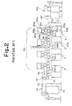
- Fig. 2 An example of the above type of printing press is shown in Fig. 2 (see Japanese Unexamined Patent Publication No. 336003/94) .
- sheets piled on a feeder 100 are fed to a printing unit 104 via a register board 101, a swing gripper device 102, and a transfer cylinder 103.
- the printing unit 104 both sides of each sheet are printed in four colors per side.
- the printing unit 104 is constructed in the following manner: Above an impression cylinder 105a having a sheet gripper, a blanket cylinder 106a, a plate cylinder 107a, and an inking unit 108a are provided to form a face side printing unit 109a. Below an impression cylinder 105b having a sheet gripper, a blanket cylinder 106b, a plate cylinder 107b, and an inking unit 108b are provided to form a reverse side printing unit 109b.
- the impression cylinder 105a of the face side printing unit 109a and the impression cylinder 105b of the reverse side printing unit 109b are horizontally connected together to constitute a 1st color double-sided printing unit A as one unit.
- 2nd color to 4th color double-sided printing units B to D are also constituted.
- These 1st color to 4th color double-sided printing units A to D are horizontally connected together by intermediate cylinders 110 to construct the printing unit 104.
- the intermediate cylinders 110 have sheet grippers, and are provided such that two of the intermediate cylinders 110 are arranged between the adjacent double-sided printing units.
- each sheet is transferred from the transfer cylinder 103 to the impression cylinder 105a of the face side printing unit 109a constituting the 1st color double-sided printing unit A, and its face side is printed in the first color. Then, the printed sheet is transferred to the impression cylinder 105b of the reverse side printing unit 109b to have its reverse side printed in the first color. Then, the sheet is fed to the 2nd color double-sided printing unit B via the two intermediate cylinders 110, and further fed to the 3rd color to 4th color double-sided printing units C to D in this order to have its face and reverse sides printed in the second to fourth colors.
- the reference numeral 111 denotes a delivery unit.
- the sheet after completion of printing is transferred from the impression cylinder 105b at the tail of the printing unit 104 to a delivery cylinder 113 via the intermediate cylinders 110 and a transport cylinder 112. From the delivery cylinder 113, the sheet is delivered onto a pile plate of a pile raising and lowering device 115 by means of a chain gripper 114.
- the impression cylinder and the plate cylinder are set at nearly the same diameter.
- transfer (gripping change) of a sheet is performed between the impression cylinder and the adjacent impression cylinder and between the impression cylinder and the adjacent intermediate cylinder, before the sheet is released from between the blanket cylinder and the impression cylinder in the preceding printing unit.
- a difference in peripheral speed due to the manufacturing error of the cylinder diameter or the like
- the tension of the sheet changes, so that the sheet maybe stretched or loosened.
- the sheet If the sheet is stretched, the sheet remains locked, with its trailing edge being pinched between the impression cylinder and the blanket cylinder, namely, the sheet remains firmly pressed against the surface of the impression cylinder.
- shear relative to the surface of the impression cylinder occurs in a printed surface of the sheet facing the surface of the impression cylinder.
- the printed surface of the sheet rubs against the surface of the impression cylinder, whereby ink adheres to the surface of the impression cylinder.
- a printed surface of a subsequent sheet is displaced relative to the ink adhering to the surface of the impression cylinder.
- the ink adhering to the surface of the impression cylinder adheres to the displaced site of the printed surface of the sheet facing the impression cylinder surface, and appears as a smudge or doubling. Scratches also occur.
- the trailing edge of the sheet is pulled toward the blanket cylinder by the attracting force of the ink that has adhered to the blanket cylinder.
- shear develops between the surface of the impression cylinder and the printed surface of the sheet facing the impression cylinder surface. Consequently, the same disadvantages occur. Such disadvantages also emerge when there is a difference in peripheral speed between the impression cylinder and the intermediate cylinder.
- the present invention provides a perfecting sheet-fed rotary press which transfers a sheet between impression cylinders of face side printing unit and impression cylinders of adjacent reverse side printing unit to print both sides of the sheet, wherein cylinders are arranged such that the sheet can be transferred between the adjacent cylinders after the sheet is released from between a blanket cylinder and the impression cylinder the preceding printing unit.
- Fig. 1 is a schematic constitutional view of a four-color perfecting sheet-fed rotary press showing an embodiment of the present invention.
- the reference numeral 1 denotes a feeding unit, 2 a printing unit, and 3 a delivery unit.
- An impression cylinder 4a at the head of the printing unit 2 is fed with sheets, which are piled on the feeding unit 1, via a register board 10, a swing gripper device 11, and a transfer cylinder 12.
- From an impression cylinder 4b at the tail of the printing unit 2 the sheet after completion of printing is transferred to a delivery cylinder 14 of the delivery unit 3 via a transport cylinder 13.
- the delivery cylinder 14 From the delivery cylinder 14, the sheet is delivered onto a pile plate of a pile raising and lowering device 16 by means of a chain gripper 15.
- the printing unit 2 consists of four face side printing units 8A to 8D, and four reverse side printing units 9A to 9D.
- the 1st color to 4th color face side printing units 8A to 8D are each formed by providing a blanket cylinder 5a, a plate cylinder 6a, and an inking unit 7a above the impression cylinder 4a having a sheet gripper.
- the 1st color to 4th color reverse side printing units 9A to 9D are each formed by providing a blanket cylinder 5b, a plate cylinder 6b, and an inking unit 7b below the impression cylinder 4b having a sheet gripper.
- the impression cylinders 4a, 4b of the four face side printing units 8A to 8D and the four reverse side printing units 9A to 9D each have a diameter twice the diameter of each of the plate cylinders 6a, 6b having the same diameter as that of the blanket cylinders 5a, 5b in rolling contact with the impression cylinders 4a, 4b.
- the so formed face side printing units 8A, 8B, 8C, 8D and reverse side printing units 9A, 9B, 9C, 9D are alternately connected, for example, such that the 1st color face side printing unit 8A is followed by the 1st color reverse side printing unit 9A, then followed by the 2nd color face side printing unit 8B, and so on.
- the impression cylinders 4a, 4b constituting the face side and reverse side printing units 8A to 8D, 9A to 9D are connected together in the horizontal direction.
- the respective impression cylinders 4a, 4b are connected together so that a line connecting the shaft centers of these impression cylinders will be zigzag.
- the present embodiment is also constituted such that after the sheet exits from between the blanket cylinder 5a and the impression cylinder 4a and between the blanket cylinder 5b and the impression cylinder 4b in the preceding printing units 8A to 8D, 9A to 9D, the sheet is transferred between the impression cylinders 4a and 4b and between the impression cylinder 4b and the transport cylinder 13.
- the cylinders are arranged such that the distance from the printing position, i.e., the point of contact between the impression cylinder 4a (4b) and the blanket cylinder 5a (5b), to the gripping change position on the next impression cylinder 4a (4b) or the transport cylinder 13 is longer than the length (L) of the sheet.
- the cylinders are arranged to meet the following relation: L ⁇ D ⁇ ( ⁇ /360) where
- each sheet is transferred from the transfer cylinder 12 to the impression cylinder 4a of the first face side printing unit 8A to have its face side printed in the first color. Then, the printed sheet is transferred to the impression cylinder 4b of the first reverse side printing unit 9A to have its reverse side printed in the first color. Then, the double-sided printed sheet is fed sequentially to the second to fourth face side printing units 8B to 8D and the second to fourth reverse side printing units 9B to 9D to have its face and reverse sides printed alternately in the second to fourth colors in the same manner as described above.
- the sheet after completion of printing is transferred from the impression cylinder 4b at the tail of the printing line to the delivery cylinder 14 via the transport cylinder 13. From the delivery cylinder 14, the sheet is delivered onto the pile plate of the pile raising and lowering device 16 by means of the chain gripper 15, as has been described earlier.
- the cylinders are arranged such that the distance from the printing position, i.e., the point of contact between the impression cylinder 4a (4b) and the blanket cylinder 5a (5b), to the gripping change position on the next impression cylinder 4a (4b) or the transport cylinder 13 is longer than the length (L) of the sheet. Furthermore, after the sheet exits from between the blanket cylinder 5a and the impression cylinder 4a and between the blanket cylinder 5b and the impression cylinder 4b in the preceding printing units 8A to 8D, 9A to 9D, the sheet is transferred between the impression cylinders 4a and 4b and between the impression cylinder 4b and the transport cylinder 13. Thus, even if the peripheral speeds of the adjacent cylinders are different, the tension of the sheet does not change during its transfer, and no printing malfunctions due to shear between the sheet and the cylinder take place. That is, the following events that would otherwise occur are prevented from happening:
- the sheet If the sheet is stretched, the sheet remains locked, with its trailing edge being pinched between the impression cylinder 4a (4b) and the blanket cylinder 5a (5b); namely, the sheet remains firmly pressed against the surface of the impression cylinder.
- shear relative to the surface of the impression cylinder occurs in the printed surface of the sheet facing the surface of the impression cylinder.
- the printed surface of the sheet rubs against the surface of the impression cylinder, whereby ink adheres to the surface of the impression cylinder.
- the printed surface of a subsequent sheet is displaced relative to the ink adhering to the surface of the impression cylinder.
- the ink adhering to the surface of the impression cylinder adheres to the displaced site of the printed surface of the sheet facing the impression cylinder surface, and appears as a smudge or doubling. Scratches also occur.
- the trailing edge of the sheet is pulled toward the blanket cylinder 5a (5b) by the attracting force of the ink that has adhered to the blanket cylinder 5a (5b).
- shear develops between the surface of the impression cylinder and the printed surface of the sheet facing the impression cylinder surface. Consequently, the same disadvantages occur.
- the present invention provides the perfecting sheet-fed rotary press which transfers a sheet between each of the impression cylinders of the face side printing units and each of the impression cylinders of the adjacent reverse side printing units to print both sides of the sheet, wherein the cylinders are arranged such that the sheet can be transferred between the adjacent cylinders after the sheet is released from between the blanket cylinder and the impression cylinder in the preceding printing unit. Even if the peripheral speeds of the adjacent cylinders are different, therefore, the tension of the sheet does not change during its transfer, so that no printing malfunctions due to shear between the sheet and the cylinder take place. Thus, the number of waste papers can be decreased.
Landscapes
- Engineering & Computer Science (AREA)
- Mechanical Engineering (AREA)
- Rotary Presses (AREA)
- Supply, Installation And Extraction Of Printed Sheets Or Plates (AREA)
Abstract
Description
Claims (3)
- A perfecting sheet-fed rotary press which transfers a sheet between impression cylinders (4a) of face side printing unit (8A to 8D) and impression cylinders (4b) of adjacent reverse side printing unit (9A to 9D) to print both sides of the sheet, characterized in that cylinders are arranged such that the sheet can be transferred between the adjacent cylinders after the sheet is released from between a blanket cylinder (5a, 5b) and the impression cylinder (4a, 4b) in the preceding printing unit.
- The perfecting sheet-fed rotary press of claim 1, characterized in that the impression cylinders (4a, 4b) of the face side printing unit (8A to 8D) and the reverse side printing unit (9A to 9D) each have a diameter twice the diameter of each of plate cylinders (6a, 6b) having the same diameter as that of blanket cylinders (5a, 5b) in rolling contact with the impression cylinders (4a, 4b).
- The perfecting sheet-fed rotary press of claim 1, characterized in that the cylinders are arranged such that the distance from a printing position, which is a point of contact between the impression cylinder (4a, 4b) and the blanket cylinder (5a, 5b), to a gripping change position on the next impression cylinder (4a, 4b) or a transport cylinder (13) is longer than the length of the sheet.
Applications Claiming Priority (3)
| Application Number | Priority Date | Filing Date | Title |
|---|---|---|---|
| JP269482/97 | 1997-10-02 | ||
| JP26948297 | 1997-10-02 | ||
| JP9269482A JPH11105249A (en) | 1997-10-02 | 1997-10-02 | Double-sided printing rotary press |
Publications (3)
| Publication Number | Publication Date |
|---|---|
| EP0906826A2 true EP0906826A2 (en) | 1999-04-07 |
| EP0906826A3 EP0906826A3 (en) | 1999-10-20 |
| EP0906826B1 EP0906826B1 (en) | 2002-11-27 |
Family
ID=17473065
Family Applications (1)
| Application Number | Title | Priority Date | Filing Date |
|---|---|---|---|
| EP19980250349 Expired - Lifetime EP0906826B1 (en) | 1997-10-02 | 1998-09-30 | Perfecting sheet-fed rotary press |
Country Status (4)
| Country | Link |
|---|---|
| EP (1) | EP0906826B1 (en) |
| JP (1) | JPH11105249A (en) |
| DE (1) | DE69809677T2 (en) |
| ES (1) | ES2190040T3 (en) |
Cited By (5)
| Publication number | Priority date | Publication date | Assignee | Title |
|---|---|---|---|---|
| EP1060883A1 (en) * | 1999-04-20 | 2000-12-20 | Mitsubishi Heavy Industries, Ltd. | Sheet-feed perfecting press |
| US8833255B2 (en) | 2010-11-11 | 2014-09-16 | Heidelberger Druckmaschinen Ag | Sheet-fed perfecting printing press without sheet reversal |
| US9662873B2 (en) | 2011-09-14 | 2017-05-30 | Komori Corporation | Combination printer |
| CN106739433A (en) * | 2016-11-18 | 2017-05-31 | 如皋市中罗印刷机械有限公司 | Book and periodical printing machine |
| EP3375610A1 (en) | 2017-03-14 | 2018-09-19 | KBA-NotaSys SA | Sheet-fed printing press for simultaneous recto-verso printing of sheets, in particular for the production of security documents |
Families Citing this family (5)
| Publication number | Priority date | Publication date | Assignee | Title |
|---|---|---|---|---|
| JP2003182031A (en) | 2001-12-14 | 2003-07-03 | Komori Corp | Coating equipment |
| JP4920237B2 (en) | 2005-10-24 | 2012-04-18 | 株式会社小森コーポレーション | Cover of the impression cylinder or transport cylinder of a printing press |
| DE102009043118A1 (en) * | 2008-10-17 | 2010-04-22 | Heidelberger Druckmaschinen Ag | Printing machine for printing on both sides of sheets |
| JP6032782B2 (en) | 2010-12-03 | 2016-11-30 | 株式会社小森コーポレーション | Banknote printing machine |
| JP6061416B2 (en) | 2010-12-14 | 2017-01-18 | 株式会社小森コーポレーション | Securities printing machine |
Family Cites Families (1)
| Publication number | Priority date | Publication date | Assignee | Title |
|---|---|---|---|---|
| US5555804A (en) * | 1993-06-25 | 1996-09-17 | Akiyama Printing Machine Manufacturing Company Ltd. | Perfecting sheet rotary offset press |
-
1997
- 1997-10-02 JP JP9269482A patent/JPH11105249A/en active Pending
-
1998
- 1998-09-30 EP EP19980250349 patent/EP0906826B1/en not_active Expired - Lifetime
- 1998-09-30 ES ES98250349T patent/ES2190040T3/en not_active Expired - Lifetime
- 1998-09-30 DE DE1998609677 patent/DE69809677T2/en not_active Expired - Lifetime
Cited By (10)
| Publication number | Priority date | Publication date | Assignee | Title |
|---|---|---|---|---|
| EP1060883A1 (en) * | 1999-04-20 | 2000-12-20 | Mitsubishi Heavy Industries, Ltd. | Sheet-feed perfecting press |
| US6431065B1 (en) | 1999-04-20 | 2002-08-13 | Mitsubishi Heavy Industries, Ltd. | Sheet-feed perfecting press |
| US8833255B2 (en) | 2010-11-11 | 2014-09-16 | Heidelberger Druckmaschinen Ag | Sheet-fed perfecting printing press without sheet reversal |
| US9662873B2 (en) | 2011-09-14 | 2017-05-30 | Komori Corporation | Combination printer |
| US9844931B2 (en) | 2011-09-14 | 2017-12-19 | Komori Corporation | Combination printer |
| CN106739433A (en) * | 2016-11-18 | 2017-05-31 | 如皋市中罗印刷机械有限公司 | Book and periodical printing machine |
| EP3375610A1 (en) | 2017-03-14 | 2018-09-19 | KBA-NotaSys SA | Sheet-fed printing press for simultaneous recto-verso printing of sheets, in particular for the production of security documents |
| WO2018167064A1 (en) | 2017-03-14 | 2018-09-20 | Kba-Notasys Sa | Sheet-fed printing press for simultaneous recto-verso printing of sheets, in particular for the production of security documents |
| CN110402196A (en) * | 2017-03-14 | 2019-11-01 | 卡巴-诺塔赛斯有限公司 | Sheet-fed presses that print both sides of a sheet simultaneously, especially for the production of security documents |
| US10875290B2 (en) | 2017-03-14 | 2020-12-29 | Kba-Notasys Sa | Sheet-fed printing press for simultaneous recto-verso printing of sheets, in particular for the production of security documents |
Also Published As
| Publication number | Publication date |
|---|---|
| EP0906826A3 (en) | 1999-10-20 |
| ES2190040T3 (en) | 2003-07-16 |
| DE69809677T2 (en) | 2003-09-18 |
| EP0906826B1 (en) | 2002-11-27 |
| DE69809677D1 (en) | 2003-01-09 |
| JPH11105249A (en) | 1999-04-20 |
Similar Documents
| Publication | Publication Date | Title |
|---|---|---|
| US4967660A (en) | Sheet-fed rotary printing press for both obverse and reverse side printing | |
| CA2185525C (en) | Multi-color printing press | |
| US4732084A (en) | Sheet-fed rotary printing machine for single-side multicolor printing and perfector printing | |
| CA2280646A1 (en) | Machine for the security printing of security papers | |
| EP0982125B1 (en) | Multicolour intaglio printing press | |
| EP0906826B1 (en) | Perfecting sheet-fed rotary press | |
| EP0982131B1 (en) | Ink unit in an intaglio printing press | |
| US5467710A (en) | Rotary printing press for two-sided printing of sheets | |
| US5555804A (en) | Perfecting sheet rotary offset press | |
| JP2000514738A (en) | Multicolor sheet printing press | |
| EP0317665B1 (en) | Sheet-fed rotary printing press | |
| JPH04267152A (en) | Sheet counting rotary offset press | |
| JPH06336003A (en) | Double-sided sheet-fed offset printing machine | |
| EP0158129B1 (en) | Rotary sheet-printing machine for perfecting or multi-colour printing | |
| US5156638A (en) | Sheet-fed rotary offset printing press with a plurality of printing units | |
| US6311616B1 (en) | Printing machine | |
| JPS60127154A (en) | Sheet-fed offset press | |
| US5365846A (en) | Format-adjustable sheet-turning device with change-over gears on a sheet-fed rotary printing press | |
| US6851360B2 (en) | Satellite-type printing press | |
| EP0420234A2 (en) | Multicolor printing press | |
| JPH079654A (en) | Double-sided multi-color sheet-fed offset printing machine | |
| JPS61104852A (en) | Direction changing device for sheet rotary press | |
| JPH1110828A (en) | Double side multicolor printing offset press | |
| JPH0436268Y2 (en) | ||
| US20080295715A1 (en) | Apparatus for introducing sheet into sheet-fed printing press |
Legal Events
| Date | Code | Title | Description |
|---|---|---|---|
| PUAI | Public reference made under article 153(3) epc to a published international application that has entered the european phase |
Free format text: ORIGINAL CODE: 0009012 |
|
| AK | Designated contracting states |
Kind code of ref document: A2 Designated state(s): CH DE ES FR GB IT LI NL SE |
|
| AX | Request for extension of the european patent |
Free format text: AL;LT;LV;MK;RO;SI |
|
| PUAL | Search report despatched |
Free format text: ORIGINAL CODE: 0009013 |
|
| RIC1 | Information provided on ipc code assigned before grant |
Free format text: 6B 41F 7/12 A, 6B 41F 21/10 B, 6B 41F 7/06 B, 6B 41F 7/02 B |
|
| AK | Designated contracting states |
Kind code of ref document: A3 Designated state(s): AT BE CH CY DE DK ES FI FR GB GR IE IT LI LU MC NL PT SE |
|
| AX | Request for extension of the european patent |
Free format text: AL;LT;LV;MK;RO;SI |
|
| 17P | Request for examination filed |
Effective date: 20000414 |
|
| AKX | Designation fees paid |
Free format text: CH DE ES FR GB IT LI NL SE |
|
| 17Q | First examination report despatched |
Effective date: 20001005 |
|
| GRAG | Despatch of communication of intention to grant |
Free format text: ORIGINAL CODE: EPIDOS AGRA |
|
| GRAG | Despatch of communication of intention to grant |
Free format text: ORIGINAL CODE: EPIDOS AGRA |
|
| GRAH | Despatch of communication of intention to grant a patent |
Free format text: ORIGINAL CODE: EPIDOS IGRA |
|
| GRAH | Despatch of communication of intention to grant a patent |
Free format text: ORIGINAL CODE: EPIDOS IGRA |
|
| GRAA | (expected) grant |
Free format text: ORIGINAL CODE: 0009210 |
|
| AK | Designated contracting states |
Kind code of ref document: B1 Designated state(s): CH DE ES FR GB IT LI NL SE |
|
| REG | Reference to a national code |
Ref country code: GB Ref legal event code: FG4D |
|
| REG | Reference to a national code |
Ref country code: CH Ref legal event code: EP |
|
| REF | Corresponds to: |
Ref document number: 69809677 Country of ref document: DE Date of ref document: 20030109 |
|
| REG | Reference to a national code |
Ref country code: CH Ref legal event code: NV Representative=s name: R. A. EGLI & CO. PATENTANWAELTE |
|
| ET | Fr: translation filed | ||
| REG | Reference to a national code |
Ref country code: ES Ref legal event code: FG2A Ref document number: 2190040 Country of ref document: ES Kind code of ref document: T3 |
|
| PLBE | No opposition filed within time limit |
Free format text: ORIGINAL CODE: 0009261 |
|
| STAA | Information on the status of an ep patent application or granted ep patent |
Free format text: STATUS: NO OPPOSITION FILED WITHIN TIME LIMIT |
|
| 26N | No opposition filed |
Effective date: 20030828 |
|
| PGFP | Annual fee paid to national office [announced via postgrant information from national office to epo] |
Ref country code: NL Payment date: 20080915 Year of fee payment: 11 Ref country code: FR Payment date: 20080915 Year of fee payment: 11 |
|
| PGFP | Annual fee paid to national office [announced via postgrant information from national office to epo] |
Ref country code: CH Payment date: 20081016 Year of fee payment: 11 |
|
| PGFP | Annual fee paid to national office [announced via postgrant information from national office to epo] |
Ref country code: SE Payment date: 20080908 Year of fee payment: 11 Ref country code: ES Payment date: 20080930 Year of fee payment: 11 |
|
| PGFP | Annual fee paid to national office [announced via postgrant information from national office to epo] |
Ref country code: IT Payment date: 20080927 Year of fee payment: 11 |
|
| PGFP | Annual fee paid to national office [announced via postgrant information from national office to epo] |
Ref country code: GB Payment date: 20081001 Year of fee payment: 11 |
|
| PGFP | Annual fee paid to national office [announced via postgrant information from national office to epo] |
Ref country code: DE Payment date: 20090923 Year of fee payment: 12 |
|
| REG | Reference to a national code |
Ref country code: NL Ref legal event code: V1 Effective date: 20100401 |
|
| REG | Reference to a national code |
Ref country code: CH Ref legal event code: PL |
|
| GBPC | Gb: european patent ceased through non-payment of renewal fee |
Effective date: 20090930 |
|
| EUG | Se: european patent has lapsed | ||
| REG | Reference to a national code |
Ref country code: FR Ref legal event code: ST Effective date: 20100531 |
|
| PG25 | Lapsed in a contracting state [announced via postgrant information from national office to epo] |
Ref country code: NL Free format text: LAPSE BECAUSE OF NON-PAYMENT OF DUE FEES Effective date: 20100401 Ref country code: FR Free format text: LAPSE BECAUSE OF NON-PAYMENT OF DUE FEES Effective date: 20090930 |
|
| PG25 | Lapsed in a contracting state [announced via postgrant information from national office to epo] |
Ref country code: LI Free format text: LAPSE BECAUSE OF NON-PAYMENT OF DUE FEES Effective date: 20090930 Ref country code: CH Free format text: LAPSE BECAUSE OF NON-PAYMENT OF DUE FEES Effective date: 20090930 |
|
| PG25 | Lapsed in a contracting state [announced via postgrant information from national office to epo] |
Ref country code: GB Free format text: LAPSE BECAUSE OF NON-PAYMENT OF DUE FEES Effective date: 20090930 |
|
| PG25 | Lapsed in a contracting state [announced via postgrant information from national office to epo] |
Ref country code: IT Free format text: LAPSE BECAUSE OF NON-PAYMENT OF DUE FEES Effective date: 20090930 |
|
| PG25 | Lapsed in a contracting state [announced via postgrant information from national office to epo] |
Ref country code: SE Free format text: LAPSE BECAUSE OF NON-PAYMENT OF DUE FEES Effective date: 20091001 |
|
| REG | Reference to a national code |
Ref country code: ES Ref legal event code: FD2A Effective date: 20110718 |
|
| REG | Reference to a national code |
Ref country code: DE Ref legal event code: R119 Ref document number: 69809677 Country of ref document: DE Effective date: 20110401 |
|
| PG25 | Lapsed in a contracting state [announced via postgrant information from national office to epo] |
Ref country code: DE Free format text: LAPSE BECAUSE OF NON-PAYMENT OF DUE FEES Effective date: 20110401 Ref country code: ES Free format text: LAPSE BECAUSE OF NON-PAYMENT OF DUE FEES Effective date: 20110706 |
|
| PG25 | Lapsed in a contracting state [announced via postgrant information from national office to epo] |
Ref country code: ES Free format text: LAPSE BECAUSE OF NON-PAYMENT OF DUE FEES Effective date: 20091001 |