EP0981926B1 - Procede et dispositif de formatage de donnees synchrones ou asynchrones - Google Patents
Procede et dispositif de formatage de donnees synchrones ou asynchrones Download PDFInfo
- Publication number
- EP0981926B1 EP0981926B1 EP98923251A EP98923251A EP0981926B1 EP 0981926 B1 EP0981926 B1 EP 0981926B1 EP 98923251 A EP98923251 A EP 98923251A EP 98923251 A EP98923251 A EP 98923251A EP 0981926 B1 EP0981926 B1 EP 0981926B1
- Authority
- EP
- European Patent Office
- Prior art keywords
- data
- synchronous
- asynchronous
- synchronous data
- superframe
- Prior art date
- Legal status (The legal status is an assumption and is not a legal conclusion. Google has not performed a legal analysis and makes no representation as to the accuracy of the status listed.)
- Expired - Lifetime
Links
Images


Classifications
-
- H—ELECTRICITY
- H04—ELECTRIC COMMUNICATION TECHNIQUE
- H04Q—SELECTING
- H04Q11/00—Selecting arrangements for multiplex systems
- H04Q11/04—Selecting arrangements for multiplex systems for time-division multiplexing
-
- H—ELECTRICITY
- H04—ELECTRIC COMMUNICATION TECHNIQUE
- H04L—TRANSMISSION OF DIGITAL INFORMATION, e.g. TELEGRAPHIC COMMUNICATION
- H04L12/00—Data switching networks
- H04L12/64—Hybrid switching systems
- H04L12/6418—Hybrid transport
-
- H—ELECTRICITY
- H04—ELECTRIC COMMUNICATION TECHNIQUE
- H04Q—SELECTING
- H04Q11/00—Selecting arrangements for multiplex systems
- H04Q11/04—Selecting arrangements for multiplex systems for time-division multiplexing
- H04Q11/0428—Integrated services digital network, i.e. systems for transmission of different types of digitised signals, e.g. speech, data, telecentral, television signals
- H04Q11/0478—Provisions for broadband connections
-
- H—ELECTRICITY
- H04—ELECTRIC COMMUNICATION TECHNIQUE
- H04L—TRANSMISSION OF DIGITAL INFORMATION, e.g. TELEGRAPHIC COMMUNICATION
- H04L12/00—Data switching networks
- H04L12/54—Store-and-forward switching systems
- H04L12/56—Packet switching systems
- H04L12/5601—Transfer mode dependent, e.g. ATM
- H04L2012/5603—Access techniques
- H04L2012/5604—Medium of transmission, e.g. fibre, cable, radio
- H04L2012/5607—Radio
-
- H—ELECTRICITY
- H04—ELECTRIC COMMUNICATION TECHNIQUE
- H04L—TRANSMISSION OF DIGITAL INFORMATION, e.g. TELEGRAPHIC COMMUNICATION
- H04L12/00—Data switching networks
- H04L12/54—Store-and-forward switching systems
- H04L12/56—Packet switching systems
- H04L12/5601—Transfer mode dependent, e.g. ATM
- H04L2012/5638—Services, e.g. multimedia, GOS, QOS
- H04L2012/5646—Cell characteristics, e.g. loss, delay, jitter, sequence integrity
- H04L2012/5652—Cell construction, e.g. including header, packetisation, depacketisation, assembly, reassembly
-
- H—ELECTRICITY
- H04—ELECTRIC COMMUNICATION TECHNIQUE
- H04L—TRANSMISSION OF DIGITAL INFORMATION, e.g. TELEGRAPHIC COMMUNICATION
- H04L12/00—Data switching networks
- H04L12/54—Store-and-forward switching systems
- H04L12/56—Packet switching systems
- H04L12/5601—Transfer mode dependent, e.g. ATM
- H04L2012/5672—Multiplexing, e.g. coding, scrambling
- H04L2012/5675—Timeslot assignment, e.g. TDMA
-
- H—ELECTRICITY
- H04—ELECTRIC COMMUNICATION TECHNIQUE
- H04L—TRANSMISSION OF DIGITAL INFORMATION, e.g. TELEGRAPHIC COMMUNICATION
- H04L12/00—Data switching networks
- H04L12/54—Store-and-forward switching systems
- H04L12/56—Packet switching systems
- H04L12/5601—Transfer mode dependent, e.g. ATM
- H04L2012/5672—Multiplexing, e.g. coding, scrambling
- H04L2012/5676—Code Division Multiple Access [CDMA]
-
- H—ELECTRICITY
- H04—ELECTRIC COMMUNICATION TECHNIQUE
- H04L—TRANSMISSION OF DIGITAL INFORMATION, e.g. TELEGRAPHIC COMMUNICATION
- H04L12/00—Data switching networks
- H04L12/64—Hybrid switching systems
- H04L12/6418—Hybrid transport
- H04L2012/6421—Medium of transmission, e.g. fibre, cable, radio, satellite
-
- H—ELECTRICITY
- H04—ELECTRIC COMMUNICATION TECHNIQUE
- H04L—TRANSMISSION OF DIGITAL INFORMATION, e.g. TELEGRAPHIC COMMUNICATION
- H04L12/00—Data switching networks
- H04L12/64—Hybrid switching systems
- H04L12/6418—Hybrid transport
- H04L2012/6445—Admission control
- H04L2012/6459—Multiplexing, e.g. TDMA, CDMA
-
- H—ELECTRICITY
- H04—ELECTRIC COMMUNICATION TECHNIQUE
- H04L—TRANSMISSION OF DIGITAL INFORMATION, e.g. TELEGRAPHIC COMMUNICATION
- H04L12/00—Data switching networks
- H04L12/64—Hybrid switching systems
- H04L12/6418—Hybrid transport
- H04L2012/6445—Admission control
- H04L2012/6462—Movable boundaries in packets or frames
Definitions
- the present invention relates generally to communication of data over a radio air interface. More particularly, the present invention relates to a method, and an associated apparatus, for formatting asynchronous and synchronous data pursuant to a common format defining a superframe, thereby to permit selective transmission of the asynchronous and synchronous data over the radio air interface.
- both the asynchronous and synchronous data can be transmitted upon a single radio link.
- different types of radio networks are able to co-exist in a single frequency band.
- the superframe is divided into separate portions. One portion defines frames dedicated to asynchronous data; another portion defines frames dedicated to synchronous data.
- the separate portions of the superframe dedicated to the communication of the different types of data can by dynamically made, thereby to utilize most efficiently the available bandwidth.
- greater portions of the superframe are allocated to the communication of asynchronous data.
- greater portions of the superframe can correspondingly be allocated for the communication of such synchronous data.
- a header portion of the superframe indicates at least which portions of the superframe contain asynchronous data and which portions of the superframe contain synchronous data.
- Processing devices can be distributed at separate locations and connected together by network connections. When connected together, the processing devices form LANs (local area networks). Groups of LANs can be connected together to form WANs (wide area networks).
- LANs local area networks
- WANs wide area networks
- ATM asynchronous transfer mode
- ATM a packet-data protocol
- data to be communicated between a sending a receiving station is formatted into fixed-length cells. Groups of the cells form packets of data which are transmitted between the sending and receiving stations to effectuate communication therebetween.
- a terminal device such as a portable computer
- a terminal device can be coupled by way of a radio link to network infrastructure of a radio communication system and, in turn, by way of the network, or other wireline connection to a data terminal.
- the terminal device can utilize the ATM protocol, and the ATM cells forming the packets of data are transmitted over the radio link between the terminal device and the data terminal.
- the communication capacity of a radio communication system is sometimes limited by the frequencies allocated to form radio channels operable therein.
- radio communications are increasingly utilized, both for conventional communication of synchronous data and also for the communication for ATM-ype data, proposals have been set forth to allocate additional frequency bands for such communications.
- Synchronous communications can typically be effectuated by narrowband techniques. And, receivers operable to receive synchronous data communicated in such manners need only receive and process narrowband signals. Conversely, at least some asynchronous communications are effectuated by broadband techniques. For example, multi-media communications typically are effectuated utilizing broadband techniques.
- a narrowband receiver typically requires less power and processing capacity than a broadband receiver as a broadband receiver must be constructed to receive data over a broad range of frequencies.
- radio receivers operable in radio networks which communicate only synchronous, narrowband data need not be constructed to receive also the broadband data, such as that which might be communicated pursuant to ATM, or other asynchronous data transmissions.
- EP-A-0 713 347 describes a method and apparatus enabling the sending of STM and ATM data over a given channel.
- the time domain for a given channel is divided into a series of successive frames, each having a plurality of time slots.
- a frame is divided into two regions, an STM region and an ATM region. The boundary between the two regions is dynamic.
- the present invention accordingly, advantageously provides a method, and an associated apparatus, for formatting asynchronous and synchronous data pursuant to a common format defining a superframe. Once formatted, the asynchronous and synchronous data can be selectively transmitted over a radio air interface between sending and receiving stations.
- the different types of data can be transmitted upon a single frequency band.
- sending and receiving stations of different radio networks are separably operable to send and to receive, respectively, communication signals communicated upon radio channels defined within a single frequency band.
- the superframe is divided into three portions.
- One portion defines frames allocated for the communication of asynchronous data.
- a second portion defines frames allocated for the communication of synchronous data.
- a third portion forms a control information portion forming a header.
- the lengths of the first and second portions allocated for the communication of asynchronous and synchronous, respectively, data can be dynamically allocated, depending upon traffic conditions.
- a greater proportion of the superframe is allocated for the communication of asynchronous data.
- a greater proportion of the frames of the superframe are allocated for the communication of the synchronous data.
- a frequency band can be allocated for the communication of more than one type of data.
- the superframe structure can be utilized in any of various communication systems utilizing different types of modulation schemes.
- the superframe structure is utilized in a TDMA (time-division multiple access) communication scheme in which a carrier is divided into time slots.
- the frames of the superframe allocated to the communication of asynchronous data are transmitted during a first set of selected time slots.
- frames of synchronous data are transmitted during a second set of time slots.
- An initial time slot is selected for the communication of the header information, thereby to inform a receiving station of the time slots during which frames of data to be transmitted thereto shall be transmitted.
- the superframe structure is utilized in a FDMA (frequency-division multiple access) communication scheme.
- FDMA frequency-division multiple access
- the header information is transmitted upon a first selected subcarrier, and other subcarriers are utilized for the communication of synchronous data and asynchronous data.
- the header information includes indications of the subcarriers upon which the asynchronous data and synchronous data are communicated.
- the superframe structure is utilized in a CDMA (code-division multiple access) communication scheme.
- the header information is coded pursuant to a first key code.
- Asynchronous data is coded pursuant to at least a second key code, and synchronous data is coded pursuant to at least a third key code.
- the header information includes information of the key codes pursuant to which the data transmitted to selected receivers is coded. Thereby, the receivers are able to decode the data transmitted thereto.
- a method, and associated apparatus structures asynchronous data and synchronous data in a radio communication system.
- the data is structured pursuant to a common data format forming a superframe.
- the asynchronous data and the synchronous data are selectively transmittable between at least one sending station and at least one receiving station, once formatted into the superframe, upon an air interface defined within a selected electromagnetic spectrum portion.
- An asynchronous data portion of the superframe is designated.
- the asynchronous data portion is of an asynchronous data length responsive to levels of asynchronous data to be transmitted between the at least one sending station and the at least one receiving station.
- a synchronous data portion of the superframe is designated.
- the synchronous data portion is of a synchronous data length responsive to levels of synchronous data to be transmitted between the at least one sending station and the at least one receiving station.
- a control information portion of the superframe is also designated.
- the control information portion indicates values of the asynchronous data length and values of the synchronous data length.
- the superframe 10 provides a common data format which permits communication of communication signals generated by different types of communication systems over a common radio link. By communicating communication signals generated during operation of the separate communication systems over the common radio link, the limited spectrum available for communications can be efficiently utilized.
- the superframe 10 of the exemplary embodiment illustrated in the Figure includes three separate portions, a header portion 14, a first data portion 16, and a second data portion 18.
- the exemplary superframe structure 10 shown in Figure 1 permits, for instance, communication of synchronous narrowband speech and data traffic and also communication of ATM (asynchronous transfer mode) cells over a common radio link, thereby to permit communication of both types of data over the common radio link.
- additional data portions are defined in the superframe to permit additional communication systems to be operable over the common communication link.
- the first and second data portions 16 and 18 are each of variable frame (or other segment) lengths.
- the lengths of the respective data portions 16 and 18 are freely selectable responsive to levels of communication required to be communicated during a particular time period by a particular one of the communication systems. Greater, or fewer, frames (or other segments) are allocated to the first or second data portion, as appropriate.
- the length of the frame portion associated with that communication system is increased to accommodate, thereby, the increased levels of communication.
- the header portion 14 of the superframe 10 includes control information indicating which frames of the data portions 16 and 18 are being transmitted to particular receiving stations of the communication systems.
- the first data portion includes a plurality of frames, various of such frames including bursts of communication signals to be communicated to different receiving stations.
- the header portion 14 of the superframe 10 includes information indicating to the various receiving stations which frames of the first data portion 16 are intended for the various receiving stations.
- the header portion 14 of the superframe 10 similarly includes control information related to the frames of the second data portion 18.
- the header portion 14 of the superframe 10 includes control information indicating the location of the communication bursts intended for a particular receiving station, a receiver operable in a narrowband, speech and data communication system need not be constructed also to receive signal bursts communicated during operation of a wireless broadband, ATM communication system sharing the same radio link.
- the control information contained in the header portion 14 of the superframe 10 provides the narrowband receiver information required to permit the receiver to tune to the appropriate narrowband channel to receive the communication bursts intended therefor.
- receiving stations intended to be operable only in the narrowband communication system need be constructed merely to receive and process a narrowband signal. A requirement otherwise to receive and to process an entire broadband signal is thereby obviated.
- Circuitry of such receiving stations for instance, need only include conventional voice coders (i.e., vocoders) used for the reception of narrowband speech and data; special voice coders to permit the reception of ATM data are not needed in such receiving stations.
- the speech traffic area is formed of n speech and data traffic segments wherein n is of a value greater or equal to zero.
- Each of the segments are capable of carrying m speech channels wherein m is greater or equal to 1.
- the value of n of speech traffic segments is specified in the header portion 14 of the superframe 10.
- traffic reservation occurs in the respective portions 16 and 18 of the superframe.
- Figure 2 illustrates the superframe 10, again shown to include a header portion 14, a first data portion 16. and a second data portion 18.
- the header portion 14 includes control information while the data portions 16 and 18 are divided into segments, here frames of data.
- the first data portion 16 is allocated for ATM traffic
- the second data portion 18 is allocated for synchronous speech and data traffic.
- a fixed-site transceiver 22 forms a sending station operable to send bursts of ATM traffic, formatted into the ATM traffic portion 16 of the superframe 10.
- Various ones of the frames of the portion 16 are allocated for communications with separate ones of mobile terminals 24.
- the header portion 14 of the superframe 10 includes control information indicating to the mobile terminals 24 which frames of the ATM traffic portion 16 are to be processed at the respective ones of the mobile terminals.
- the arrows 26 are representative of the formatting of the ATM traffic portion 16 of the superframe 10 with the frames of ATM traffic and the reception, and processing, of frames of the ATM traffic portion 16.
- FIG. 2 further illustrates a fixed-site transceiver 28 operable in a synchronous, narrowband speech and data communication system.
- the transceiver 28 here forms a sending station operable to communicate bursts of synchronous data to selected ones of a plurality of mobile terminals, here mobile terminals 32, pursuant to the superframe 10 format.
- the arrows 34 shown in the Figure are representative of communication of the frames of synchronous data communicated pursuant to the format of the superframe 10 to individual ones of the mobile terminals 32.
- Control information contained in the header portion 14 of the superframe 10 provide indications to the mobile terminals 32 as to where to locate the frames of synchronous data transmitted thereto. Such portions of the superframe 10 are processed by the respective ones of the mobile terminals 32.
- Figure 3 again illustrates the superframe 10, again shown to be formed of a header portion 14, and first and second data portions 16 and 18.
- the first data portion 16 is again allocated for ATM traffic
- the data portion 18 is allocated for narrowband, synchronous speech and data traffic.
- a fixed-site transceiver 22 and mobile terminals 24 of an ATM communication system are again shown in the Figure.
- a fixed-site transceiver 28 and mobile terminals 32 of a synchronous speech and data communication system are also shown in the Figure.
- the fixed-site transceivers 22 and 28 form receiving stations for receiving uplink transmissions generated by the mobile terminals 24 and 32, respectively.
- the arrows 36 are representative of the transmission of uplink bursts communicated by individual ones of the mobile terminals 24 to the fixed-site transceiver 22.
- the header portion 14 includes control information indicating to the receiving station formed of the transceiver 22 to the location of the uplink transmissions communicated by the various ones of the mobile terminals 24.
- the arrows 38 shown in the Figure are representative of the uplink transmissions by individual ones of the mobile terminals 32 of the synchronous speech and data communication system. Again, control information contained in the header portion 14 indicates to the fixed-site transceiver 28 the location of the frames of data forming the uplink transmissions of the respective ones of the mobile terminals 32.
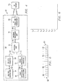
- FIG 4 illustrates a communication system, shown generally at 50, having a sending station 52 and a receiving station 55 connected together by way of a radio link.
- Data to be communicated between the sending station 52 and the receiving station 55 is formatted pursuant to the superframe 10 shown in Figure 1.
- Both asynchronous data traffic, such as ATM data traffic, and synchronous voice and data traffic can be communicated over the same radio link to one or more receiving stations 55.
- the sending station 52 is operable to transmit both ATM data traffic and synchronous speech and data traffic.
- the sending station 52 includes an ATM data source 54 forming a source of ATM data to be communicated to the receiving station 54.
- ATM data generated by the ATM data source 54 is provided by way of the line 56 to an ATM cell formatter 58 which formats the ATM data into ATM cells, a conventional manner by which ATM data is formatted.
- the ATM cells are provided by way of the line 62 to a protocol unit 64.
- the sending station 52 further includes a synchronous speech and data source 66. Synchronous speech and data generated by the source 66 are provided by way of the line 68 to a synchronous speech and data formatter 72 which formats the synchronous speech and data into synchronous speech/data frames on the line 74.
- the line 74 is coupled to the protocol unit 64, thereby to provide the frames formed by the formatter 72 to the protocol unit 64.
- the data sources 54 and 66 and formatters 58 and 72 are functionally formed at a personal computer or work station.
- the protocol unit 64 is functionally formed at a radio base station with the lines 62 and 74 extending to the base station.
- the protocol unit 64 is functionally formed at a mobile terminal.
- the data sources 54 and 66 and formatters 58 and 72 again functionally formed at a personal computer or a work station, are coupled to the mobile terminal by way of the lines 62 and 74, forming either a wireline connection or some type of RF (radio frequency), such as an infrared, connection.
- RF radio frequency
- the protocol unit 64 performs functions such as MAC, LLC, and handovers. Interleaving of the frames and cells applied to the protocol unit 64 by way of the lines 62 and 74, provides for the formation of superframes of data such as the superframe 10 shown previously in Figure 1. The control information forming the header portion of the superframe is also provided at the protocol unit 64.
- the protocol unit 64 is coupled by way of the line 76 to a baseband processing unit 78.
- Baseband processing is performed by the baseband processing unit 78.
- the baseband processing unit 78 is coupled by way of the line 80 to a HF (high frequency) transceiver circuit 82.
- the front-end transceiver 82 is operable to convert the data, formatted into the superframes, into radio frequency signals transmittable over the radio link extending between the sending station 52 and the receiving station 55.
- the structure of the receiving station 55 includes elements analogous to, and generally the reverse of, the elements shown to form the sending station 52. That is to say, for instance, the front-end transceiver, when forming a portion of the receiving station, down converts radio frequency signals into baseband signals which can be processed by a baseband processing unit.
- the protocol unit extracts the ATM cells and speech data frames, as appropriate, from the received superframes, and the data sources 54 and 66, conversely, form data sinks.
- the communication system 50 is operable pursuant to a TDMA (time-division, multiple access) communication scheme.
- Figure 5 illustrates an exemplary frames 83 formed pursuant to a TDMA communication scheme. Each frame is formed of a plurality of time slots 84.
- the exemplary frames shown in the Figure are formed of eight time slots, each of which contains a communication burst of data to be communicated to a particular receiving station. Header information is contained in at least one time slot, here the leading time slot.
- the communication system is operable pursuant to an FDMA (frequency-division, multiple access) communication scheme.
- Figure 6 illustrates a plurality of carriers, here carrier f 1 -f n .
- Header information is transmitted upon one of the carriers.
- Other data is communicated upon other selected carriers.
- a narrowband receiver extracts information from the header information transmitted upon one of the selected carriers. Such information provides the receiving station with indications of to which channel to tune to receive bursts of communication signals transmitted thereto.
- the communication system 50 is operable pursuant to a CDMA (code-division, multiple access) communication scheme.
- Figure 7 illustrates various signals communicated over the same range of frequencies.
- keys indicated by the blocks 86, are used at a receiving station to decode coded information transmitted thereto.
- Information decoded pursuant to decoding by a first key provides information to the receiving station to permit the receiving station to decode a communication burst intended for the receiving station.
- Figure 8 illustrates a method, shown generally at 90, of an embodiment of the present invention.
- the method structures asynchronous data and synchronous data in a radio communication system pursuant to a common data format forming a superframe.
- an asynchronous data portion of the superframe is designated.
- the asynchronous data portion is of a data length respc ive to levels of asynchronous data to be transmitted between at least one sending station and at least one receiving station.
- a synchronous data portion of the superframe is also designated, as indicated by the block 94.
- the synchronous data portion is of a data length responsive to levels of synchronous data to be transmitted between the at least one sending station and the at least one receiving station.
- control information portion of the superframe is designated.
- the control information portion indicates values of the asynchronous data length and values of the synchronous data length.
- Operation of an embodiment of the present invention thereby advantageously permits both asynchronous and synchronous data to be transmitted upon a single radio link.
- Different types of radio networks are thereby able to co-exist in a single frequency band.
- the separate portions of the superframe dedicated to the communication of the different types of data can by dynamically made, thereby to utilize most efficiently the available bandwidth. Allocation and reallocation of the lengths of the separate data-containing portions of the superframe are made, as traffic conditions change, so that the possible levels of communications are permitted over the single frequency band.
Landscapes
- Engineering & Computer Science (AREA)
- Computer Networks & Wireless Communication (AREA)
- Signal Processing (AREA)
- Mobile Radio Communication Systems (AREA)
- Time-Division Multiplex Systems (AREA)
Claims (15)
- Procédé pour structurer des données asynchrones et des données synchrones dans un système de radiocommunication conformément à un format de données commun formant une supertrame, les données asynchrones et les données synchrones pouvant être transmises sélectivement entre au moins une station émettrice et au moins une station réceptrice, une fois formatées dans la supertrame, sur une interface air définie à l'intérieur d'une partie sélectionnée du spectre électromagnétique, ce procédé comprenant les étapes consistant à :désigner une partie de données asynchrones de la supertrame, la partie de données asynchrones ayant une longueur de données asynchrones qui dépend de niveaux de données asynchrones à transmettre entre l'au moins une station émettrice et l'au moins une station réceptrice;désigner une partie de données synchrones de la supertrame, la partie de données synchrones ayant une longueur de données synchrones qui dépend de niveaux de données synchrones à transmettre entre l'au moins une station émettrice et l'au moins une station réceptrice; caractérisé en ce queon désigne une partie d'information de commande de la supertrame, la partie d'information de commande indiquant des valeurs de la longueur de données asynchrones et des valeurs de la longueur de données synchrones dans la supertrame.
- Procédé selon la revendication 1, dans lequel la partie d'information de commande forme une partie d'en-tête placée à une partie d'extrémité avant de la supertrame.
- Procédé selon la revendication 2, dans lequel la partie de données asynchrones désignée pendant l'étape de désignation de la partie de données asynchrones est placée de façon à suivre la partie d'en-tête lorsque la longueur de données asynchrones est une longueur d'au moins une trame de données asynchrones.
- Procédé selon la revendication 3, dans lequel la partie de données synchrones désignée pendant l'étape de désignation de la partie de données synchrones est placée de façon à suivre la partie asynchrone lorsque la longueur de données synchrones est une longueur d'au moins une trame de données synchrones.
- Procédé selon la revendication 2, dans lequel la partie de données synchrones désignée pendant l'étape de désignation de la partie de données synchrones est placée de façon à suivre la partie d'en-tête lorsque la longueur de données synchrones est une longueur d'au moins une trame de données synchrones.
- Procédé selon la revendication 1, dans lequel l'au moins une station émettrice comprend une première multiplicité de stations émettrices, chacune étant capable d'émettre des données asynchrones, dans lequel la partie de données asynchrones désignée pendant l'étape de désignation des parties de données asynchrones comprend des trames, et dans lequel l'étape de désignation de la partie de données asynchrones comprend l'allocation d'au moins une trame de la partie de données asynchrones à chaque station émettrice de la première multiplicité de stations émettrices qui doit émettre des données asynchrones.
- Procédé selon la revendication 6, dans lequel l'au moins une station réceptrice comprend une première multiplicité de stations réceptrices, chacune étant capable de recevoir des données asynchrones, et dans lequel la partie d'information de commande désignée pendant l'étape de désignation de la partie d'information de commande indique en outre quelle trame de l'au moins une trame de la partie de données asynchrones est émise par des stations individuelles de la première multiplicité de stations émettrices, vers des stations individuelles de la première multiplicité de stations réceptrices.
- Procédé selon la revendication 1, dans lequel l'au moins une station émettrice comprend une première multiplicité de stations émettrices, chacune étant capable d'émettre des données synchrones, dans lequel la partie de données synchrones désignée pendant l'étape de désignation des parties de données synchrones comprend des trames, et dans lequel l'étape de désignation de la partie de données synchrones comprend l'allocation d'au moins une trame de la partie de données synchrones à chaque station émettrice de la première multiplicité qui doit émettre des données synchrones.
- Procédé selon la revendication 8, dans lequel l'au moins une station réceptrice comprend une première multiplicité de stations réceptrices, chacune étant capable de recevoir des données synchrones, et dans lequel la partie d'information de commande désignée pendant l'étape de désignation de la partie d'information de commande indique en outre quelle trame de l'au moins une trame de la partie de données synchrones est émise par des stations individuelles de la première multiplicité de stations émettrices vers des stations individuelles de la première multiplicité de stations réceptrices.
- Procédé selon la revendication 1, dans lequel l'au moins une station émettrice comprend au moins une station émettrice multi-données capable d'émettre sélectivement à la fois des données asynchrones et des données synchrones, dans lequel la partie de données synchrones comprend des trames, dans lequel la partie de données asynchrones comprend des trames, et dans lequel l'étape de désignation de la partie de données asynchrones comprend l'allocation d'au moins une trame de la partie de données asynchrones à l'au moins une station émettrice multi-données.
- Procédé selon la revendication 10, dans lequel l'étape de désignation de la partie de données synchrones comprend l'allocation d'au moins une trame de la partie de données synchrones à l'au moins une station émettrice multi-données.
- Procédé selon la revendication 11, dans lequel l'au moins une station réceptrice comprend au moins une station réceptrice multi-données capable de recevoir sélectivement à la fois des données asynchrones et des données synchrones, et dans lequel la partie d'information de commande désignée pendant l'étape de désignation de la partie d'information de commande indique en outre quelle trame de la partie de données asynchrones et quelle trame de l'au moins une trame de la partie de données synchrones doit être reçue par l'au moins une station réceptrice multi-données.
- Procédé selon la revendication 1, dans lequel le système de radiocommunication comprend un système de communication AMRT (accès multiple par répartition dans le temps) définissant au moins une porteuse, l'au moins une porteuse étant divisée en une multiplicité de créneaux temporels, et dans lequel la partie d'information de commande indique en outre pendant quels créneaux temporels de la multiplicité de créneaux temporels des données asynchrones doivent être émises, et pendant quels créneaux temporels de la multiplicité de créneaux temporels des données synchrones doivent être émises.
- Procédé selon la revendication 1, dans lequel le système de radiocommunication comprend un système de communication AMRF (accès multiple par répartition en fréquence) définissant une multiplicité de sous-porteuses, et dans lequel la partie d'information de commande indique en outre sur quelles sous-porteuses de la multiplicité de sous-porteuses les données asynchrones doivent être émises, et sur quelles sous-porteuses de la multiplicité de sous-porteuses les données synchrones doivent être émises.
- Appareil pour structurer des données asynchrones et des données synchrones conformément à un format de données commun formant une supertrame, les données asynchrones pouvant être émises sélectivement, une fois qu'elles sont formatées dans la supertrame, sur une interface air définie à l'intérieur d'une partie sélectionnée du spectre électromagnétique, cet appareil étant incorporé dans un système de radiocommunication ayant au moins une station émettrice et au moins une station réceptrice et comprenant :un élément de désignation de partie de données asynchrones couplé pour recevoir des indications de niveau de données asynchrones à transmettre entre l'au moins une station émettrice et l'au moins une station réceptrice, cet élément de désignation de partie de données asynchrones étant destiné à désigner une première partie de la supertrame devant avoir une première longueur sélectionnée, la première longueur sélectionnée dépendant des indications des niveaux des données asynchrones;une partie de données synchrones couplée pour recevoir des indications de niveaux de données synchrones à transmettre entre l'au moins une station émettrice et l'au moins une station réceptrice, cet élément de désignation de partie de données synchrones étant destiné à désigner une deuxième partie de la supertrame devant avoir une deuxième longueur sélectionnée, la deuxième longueur sélectionnée dépendant d'indications des niveaux des données synchrones;caractérisé par
un élément de désignation d'information de commande couplé pour recevoir des indications de la première longueur sélectionnée désignée par l'élément de désignation de partie de données asynchrones et des indications de la deuxième longueur sélectionnée désignée par l'élément de désignation de partie de données synchrones, cet élément de désignation d'information de commande étant destiné à désigner une partie d'information de commande de la supertrame dans la supertrame, la partie d'information de commande ayant des valeurs dépendant respectivement des indications des première et deuxième longueurs sélectionnées.
Applications Claiming Priority (3)
| Application Number | Priority Date | Filing Date | Title |
|---|---|---|---|
| US856332 | 1997-05-14 | ||
| US08/856,332 US5943344A (en) | 1997-05-14 | 1997-05-14 | Method and apparatus for formatting synchronous and asynchronous data |
| PCT/SE1998/000849 WO1998052380A1 (fr) | 1997-05-14 | 1998-05-08 | Procede et dispositif de formatage de donnees synchrones ou asynchrones |
Publications (2)
| Publication Number | Publication Date |
|---|---|
| EP0981926A1 EP0981926A1 (fr) | 2000-03-01 |
| EP0981926B1 true EP0981926B1 (fr) | 2006-07-19 |
Family
ID=25323355
Family Applications (1)
| Application Number | Title | Priority Date | Filing Date |
|---|---|---|---|
| EP98923251A Expired - Lifetime EP0981926B1 (fr) | 1997-05-14 | 1998-05-08 | Procede et dispositif de formatage de donnees synchrones ou asynchrones |
Country Status (12)
| Country | Link |
|---|---|
| US (1) | US5943344A (fr) |
| EP (1) | EP0981926B1 (fr) |
| JP (1) | JP3871147B2 (fr) |
| KR (1) | KR100547087B1 (fr) |
| CN (1) | CN1227946C (fr) |
| AU (1) | AU753025B2 (fr) |
| BR (1) | BR9809612A (fr) |
| CA (1) | CA2289857C (fr) |
| DE (1) | DE69835286T2 (fr) |
| RU (1) | RU2225081C2 (fr) |
| TW (1) | TW384584B (fr) |
| WO (1) | WO1998052380A1 (fr) |
Cited By (1)
| Publication number | Priority date | Publication date | Assignee | Title |
|---|---|---|---|---|
| US10630437B2 (en) | 2014-03-20 | 2020-04-21 | Interdigital Patent Holdings, Inc. | Method and apparatus for non-orthogonal access in LTE systems |
Families Citing this family (34)
| Publication number | Priority date | Publication date | Assignee | Title |
|---|---|---|---|---|
| JP3003779B2 (ja) * | 1997-06-24 | 2000-01-31 | 日本電気株式会社 | 通信システム |
| US6480477B1 (en) * | 1997-10-14 | 2002-11-12 | Innowave Eci Wireless Systems Ltd. | Method and apparatus for a data transmission rate of multiples of 100 MBPS in a terminal for a wireless metropolitan area network |
| JP3307573B2 (ja) * | 1997-11-12 | 2002-07-24 | 沖電気工業株式会社 | 無線通信装置 |
| US6389038B1 (en) | 1999-01-26 | 2002-05-14 | Net 2 Phone | Voice IP bandwidth utilization |
| US6377817B1 (en) * | 1999-05-03 | 2002-04-23 | Nokia Mobile Phones Ltd. | Asymmetric data transmission for use in a multi-modulation environment |
| EP1052876A1 (fr) * | 1999-05-11 | 2000-11-15 | Alcatel | Système de transmission tenant compte des exigences des différents trafics supportés, émetteur et récepteur correspondants |
| US6920156B1 (en) | 1999-12-01 | 2005-07-19 | Cisco Technology, Inc. | Method and system for transporting synchronous and asynchronous traffic on a synchronous bus of a telecommunications node |
| US6628657B1 (en) * | 1999-12-01 | 2003-09-30 | Cisco Technology, Inc. | Method and system for transporting synchronous and asynchronous traffic on a bus of a telecommunications node |
| US6760327B1 (en) | 1999-12-01 | 2004-07-06 | Cisco Technology, Inc. | Rate adjustable backplane and method for a telecommunications node |
| US6658620B1 (en) * | 2000-01-11 | 2003-12-02 | Northrop Grumman Corporation | Burst and packet wireless transmission using product codes with iterative decoding |
| JP2002077210A (ja) * | 2000-08-25 | 2002-03-15 | Fujitsu Denso Ltd | Pon伝送システム、atm−pon伝送システム、光ネットワーク装置、及び光回線終端装置 |
| EP1425895A2 (fr) * | 2001-09-10 | 2004-06-09 | GlobeSpan Virata, Inc. | Besoins en repartition dynamique du debit |
| WO2004004284A1 (fr) * | 2001-09-10 | 2004-01-08 | Globespan Virata Incorporated | Structure pour voix decoupee en canaux utilisant sdsl |
| US20030086436A1 (en) * | 2001-09-10 | 2003-05-08 | Massimo Sorbara | Recommendation for a 1-bit Z channel for DRR |
| AU2002333537A1 (en) * | 2001-09-10 | 2003-03-24 | Globespan Virata Incorporated | Recommendation for a 1-bit z channel for drr |
| JP4142386B2 (ja) * | 2002-10-03 | 2008-09-03 | 株式会社エヌ・ティ・ティ・ドコモ | 移動通信システム、移動通信方法及び基地局 |
| KR100561393B1 (ko) * | 2002-11-30 | 2006-03-16 | 삼성전자주식회사 | 무선 네트워크에 있어서 매체 접근 제어 방법 및 시스템 |
| US8599764B2 (en) * | 2003-09-02 | 2013-12-03 | Qualcomm Incorporated | Transmission of overhead information for reception of multiple data streams |
| US8477809B2 (en) * | 2003-09-02 | 2013-07-02 | Qualcomm Incorporated | Systems and methods for generalized slot-to-interlace mapping |
| US8509051B2 (en) * | 2003-09-02 | 2013-08-13 | Qualcomm Incorporated | Multiplexing and transmission of multiple data streams in a wireless multi-carrier communication system |
| US7221680B2 (en) * | 2003-09-02 | 2007-05-22 | Qualcomm Incorporated | Multiplexing and transmission of multiple data streams in a wireless multi-carrier communication system |
| US8526412B2 (en) * | 2003-10-24 | 2013-09-03 | Qualcomm Incorporated | Frequency division multiplexing of multiple data streams in a wireless multi-carrier communication system |
| KR20060096450A (ko) * | 2003-10-24 | 2006-09-11 | 콸콤 인코포레이티드 | 다수의 데이터 스트림들의 수신을 위한 오버헤드 정보의전송 |
| US20070274214A1 (en) * | 2003-11-18 | 2007-11-29 | Oleg Logvinov | System and method for combining synchronous and asynchronous communications on a communications network |
| US8089855B2 (en) * | 2004-06-04 | 2012-01-03 | Qualcomm Incorporated | Transmission of overhead information for broadcast and multicast services in a wireless communication system |
| EP1655918A3 (fr) * | 2004-11-03 | 2012-11-21 | Broadcom Corporation | Mode à faible débit et à longue portée pour des réseaux locals OFDM sans fil |
| US7979561B2 (en) * | 2005-03-10 | 2011-07-12 | Qualcomm Incorporated | Method of multiplexing over an error-prone wireless broadcast channel |
| US7917747B2 (en) * | 2007-03-22 | 2011-03-29 | Igt | Multi-party encryption systems and methods |
| US20090175210A1 (en) * | 2007-07-26 | 2009-07-09 | Qualcomm Incorporated | Multiplexing and transmission of multiple data streams in a wireless multi-carrier communication system |
| US20110013580A1 (en) * | 2008-03-06 | 2011-01-20 | Kyocera Corporation | Communication method and a base station apparatus using the method |
| GB2501081B (en) | 2012-04-11 | 2017-08-30 | Sca Ipla Holdings Inc | Telecommunications apparatus and methods |
| GB2501080A (en) * | 2012-04-11 | 2013-10-16 | Sca Ipla Holdings Inc | Telecommunication apparatus and methods |
| KR20170075627A (ko) * | 2015-12-23 | 2017-07-03 | 삼성전자주식회사 | 통신 또는 방송 시스템에서 채널 부호화/복호화 방법 및 장치 |
| EP3378164B1 (fr) | 2015-12-23 | 2022-04-27 | Samsung Electronics Co., Ltd. | Appareil et procédé de codage et de décodage de canal dans un système de diffusion ou de communication |
Family Cites Families (2)
| Publication number | Priority date | Publication date | Assignee | Title |
|---|---|---|---|---|
| JP3262142B2 (ja) * | 1992-01-16 | 2002-03-04 | 富士通株式会社 | Atmセル化装置、atmセル化方法、ノード、及びノードにおける多重化方法 |
| US5570355A (en) * | 1994-11-17 | 1996-10-29 | Lucent Technologies Inc. | Method and apparatus enabling synchronous transfer mode and packet mode access for multiple services on a broadband communication network |
-
1997
- 1997-05-14 US US08/856,332 patent/US5943344A/en not_active Expired - Lifetime
-
1998
- 1998-05-08 WO PCT/SE1998/000849 patent/WO1998052380A1/fr active IP Right Grant
- 1998-05-08 DE DE69835286T patent/DE69835286T2/de not_active Expired - Lifetime
- 1998-05-08 KR KR1019997010371A patent/KR100547087B1/ko not_active IP Right Cessation
- 1998-05-08 BR BR9809612-5A patent/BR9809612A/pt not_active Application Discontinuation
- 1998-05-08 RU RU99126435/09A patent/RU2225081C2/ru not_active IP Right Cessation
- 1998-05-08 CN CNB98805096XA patent/CN1227946C/zh not_active Expired - Fee Related
- 1998-05-08 AU AU75585/98A patent/AU753025B2/en not_active Ceased
- 1998-05-08 JP JP54913298A patent/JP3871147B2/ja not_active Expired - Lifetime
- 1998-05-08 CA CA002289857A patent/CA2289857C/fr not_active Expired - Fee Related
- 1998-05-08 EP EP98923251A patent/EP0981926B1/fr not_active Expired - Lifetime
- 1998-05-13 TW TW087107406A patent/TW384584B/zh not_active IP Right Cessation
Cited By (2)
| Publication number | Priority date | Publication date | Assignee | Title |
|---|---|---|---|---|
| US10630437B2 (en) | 2014-03-20 | 2020-04-21 | Interdigital Patent Holdings, Inc. | Method and apparatus for non-orthogonal access in LTE systems |
| US11483108B2 (en) | 2014-03-20 | 2022-10-25 | Interdigital Patent Holdings, Inc. | Method and apparatus for non-orthogonal access in LTE systems |
Also Published As
| Publication number | Publication date |
|---|---|
| JP2001526011A (ja) | 2001-12-11 |
| DE69835286D1 (de) | 2006-08-31 |
| AU7558598A (en) | 1998-12-08 |
| CA2289857C (fr) | 2008-02-12 |
| US5943344A (en) | 1999-08-24 |
| RU2225081C2 (ru) | 2004-02-27 |
| CA2289857A1 (fr) | 1998-11-19 |
| KR20010012418A (ko) | 2001-02-15 |
| WO1998052380A1 (fr) | 1998-11-19 |
| CN1227946C (zh) | 2005-11-16 |
| TW384584B (en) | 2000-03-11 |
| EP0981926A1 (fr) | 2000-03-01 |
| CN1256064A (zh) | 2000-06-07 |
| JP3871147B2 (ja) | 2007-01-24 |
| KR100547087B1 (ko) | 2006-01-26 |
| BR9809612A (pt) | 2000-07-04 |
| AU753025B2 (en) | 2002-10-03 |
| DE69835286T2 (de) | 2007-07-12 |
Similar Documents
| Publication | Publication Date | Title |
|---|---|---|
| EP0981926B1 (fr) | Procede et dispositif de formatage de donnees synchrones ou asynchrones | |
| CN1930799B (zh) | 用于在宽带无线通信系统中发送/接收数据脉冲串的方法 | |
| US7684368B2 (en) | Dynamic link assignment in a communication system | |
| EP2208315B1 (fr) | Systèmes OFDM à compatibilités multiples avec différentes bandes passantes | |
| EP0910181B1 (fr) | Modulation large bande CDMA dynamique et optimisée | |
| US6967943B1 (en) | Time division multiple access radio systems | |
| US6532223B1 (en) | Communication method, transmission method, reception method, base station and terminal | |
| KR100463965B1 (ko) | 무선통신시스템에서코드어의복호화를간략화하는방법및장치 | |
| EP0844796A2 (fr) | Méthode de communication | |
| EP1703647B1 (fr) | Procédures de signalement de configuration d'un canal physique | |
| US20070060149A1 (en) | Frame communication apparatus and method in broadband wireless communication system | |
| US7088697B1 (en) | Methods and apparatus for transmitting data in a radio communication system including signaling allocation of a common channel | |
| WO1997047112A3 (fr) | Appareil et procede pour reseau local (mta) sans fil de commutation par paquets, a reservation | |
| US6608827B1 (en) | Method for increasing the communication capacity of a cellular telephone system | |
| KR19980042634A (ko) | 통신방법, 기지국 및 단말장치 | |
| WO1998020632A1 (fr) | Procede de gestion d'energie par synchronisation d'un systeme de communications | |
| US7106705B1 (en) | Method and communications systems for transmitting data for a combination of several services via jointly used physical channels | |
| EP1681812B1 (fr) | Procédé de transmission des canaux de radiodiffusion dans un système cellulaire de communications sans fil | |
| JPH05336061A (ja) | 移動無線システム | |
| CA2263775A1 (fr) | Systeme de radiocommunication numerique a constitution simple permettant de varier le mode de capacite de transmission | |
| JP3189204B2 (ja) | 移動体通信システムにおける局間伝送路の回線構成方法 | |
| US6859490B1 (en) | Method and system for wireless communications using different modulation techniques to provide guard times | |
| EP1244236A2 (fr) | Format des éléments formant des tables de correspondance dans des systèmes point-à- multipoint avec de modes physicaux différents | |
| Noerpel et al. | Personal access communications system: a flexible PCS standard | |
| JPH10233728A (ja) | 無線電話装置 |
Legal Events
| Date | Code | Title | Description |
|---|---|---|---|
| PUAI | Public reference made under article 153(3) epc to a published international application that has entered the european phase |
Free format text: ORIGINAL CODE: 0009012 |
|
| 17P | Request for examination filed |
Effective date: 19991109 |
|
| AK | Designated contracting states |
Kind code of ref document: A1 Designated state(s): DE FI FR GB IT |
|
| RIN1 | Information on inventor provided before grant (corrected) |
Inventor name: BAUTZ, GREGOR Inventor name: NIEBERT, NORBERT Inventor name: KOCH, WOLFGANG Inventor name: KHUN JUSH, JAMSHID Inventor name: KELLER, RALF |
|
| RAP1 | Party data changed (applicant data changed or rights of an application transferred) |
Owner name: TELEFONAKTIEBOLAGET LM ERICSSON (PUBL) |
|
| 17Q | First examination report despatched |
Effective date: 20041210 |
|
| GRAP | Despatch of communication of intention to grant a patent |
Free format text: ORIGINAL CODE: EPIDOSNIGR1 |
|
| GRAS | Grant fee paid |
Free format text: ORIGINAL CODE: EPIDOSNIGR3 |
|
| GRAA | (expected) grant |
Free format text: ORIGINAL CODE: 0009210 |
|
| AK | Designated contracting states |
Kind code of ref document: B1 Designated state(s): DE FI FR GB IT |
|
| PG25 | Lapsed in a contracting state [announced via postgrant information from national office to epo] |
Ref country code: IT Free format text: LAPSE BECAUSE OF FAILURE TO SUBMIT A TRANSLATION OF THE DESCRIPTION OR TO PAY THE FEE WITHIN THE PRESCRIBED TIME-LIMIT;WARNING: LAPSES OF ITALIAN PATENTS WITH EFFECTIVE DATE BEFORE 2007 MAY HAVE OCCURRED AT ANY TIME BEFORE 2007. THE CORRECT EFFECTIVE DATE MAY BE DIFFERENT FROM THE ONE RECORDED. Effective date: 20060719 Ref country code: FI Free format text: LAPSE BECAUSE OF FAILURE TO SUBMIT A TRANSLATION OF THE DESCRIPTION OR TO PAY THE FEE WITHIN THE PRESCRIBED TIME-LIMIT Effective date: 20060719 |
|
| REG | Reference to a national code |
Ref country code: GB Ref legal event code: FG4D |
|
| REF | Corresponds to: |
Ref document number: 69835286 Country of ref document: DE Date of ref document: 20060831 Kind code of ref document: P |
|
| ET | Fr: translation filed | ||
| PLBE | No opposition filed within time limit |
Free format text: ORIGINAL CODE: 0009261 |
|
| STAA | Information on the status of an ep patent application or granted ep patent |
Free format text: STATUS: NO OPPOSITION FILED WITHIN TIME LIMIT |
|
| 26N | No opposition filed |
Effective date: 20070420 |
|
| PGFP | Annual fee paid to national office [announced via postgrant information from national office to epo] |
Ref country code: GB Payment date: 20130528 Year of fee payment: 16 Ref country code: DE Payment date: 20130530 Year of fee payment: 16 |
|
| PGFP | Annual fee paid to national office [announced via postgrant information from national office to epo] |
Ref country code: FR Payment date: 20130606 Year of fee payment: 16 |
|
| REG | Reference to a national code |
Ref country code: DE Ref legal event code: R119 Ref document number: 69835286 Country of ref document: DE |
|
| GBPC | Gb: european patent ceased through non-payment of renewal fee |
Effective date: 20140508 |
|
| REG | Reference to a national code |
Ref country code: FR Ref legal event code: ST Effective date: 20150130 |
|
| REG | Reference to a national code |
Ref country code: DE Ref legal event code: R119 Ref document number: 69835286 Country of ref document: DE Effective date: 20141202 |
|
| PG25 | Lapsed in a contracting state [announced via postgrant information from national office to epo] |
Ref country code: DE Free format text: LAPSE BECAUSE OF NON-PAYMENT OF DUE FEES Effective date: 20141202 |
|
| PG25 | Lapsed in a contracting state [announced via postgrant information from national office to epo] |
Ref country code: GB Free format text: LAPSE BECAUSE OF NON-PAYMENT OF DUE FEES Effective date: 20140508 Ref country code: FR Free format text: LAPSE BECAUSE OF NON-PAYMENT OF DUE FEES Effective date: 20140602 |