EP0981201A2 - Détecteur de passages par zéro puis procédé de détermination d'une valeur de passage par zéro - Google Patents
Détecteur de passages par zéro puis procédé de détermination d'une valeur de passage par zéro Download PDFInfo
- Publication number
- EP0981201A2 EP0981201A2 EP99114025A EP99114025A EP0981201A2 EP 0981201 A2 EP0981201 A2 EP 0981201A2 EP 99114025 A EP99114025 A EP 99114025A EP 99114025 A EP99114025 A EP 99114025A EP 0981201 A2 EP0981201 A2 EP 0981201A2
- Authority
- EP
- European Patent Office
- Prior art keywords
- trigger
- amplitude
- level
- pulse packet
- signal
- Prior art date
- Legal status (The legal status is an assumption and is not a legal conclusion. Google has not performed a legal analysis and makes no representation as to the accuracy of the status listed.)
- Granted
Links
Images

Classifications
-
- H—ELECTRICITY
- H03—ELECTRONIC CIRCUITRY
- H03K—PULSE TECHNIQUE
- H03K5/00—Manipulating of pulses not covered by one of the other main groups of this subclass
- H03K5/153—Arrangements in which a pulse is delivered at the instant when a predetermined characteristic of an input signal is present or at a fixed time interval after this instant
- H03K5/1536—Zero-crossing detectors
Definitions
- the present invention relates to a zero crossing detector and method for detecting the zero crossing of a particular pulse in a packet of individual pulses particularly pulses obtained from an ultrasound source.
- a piezoelectric crystal does not emit a single pulse when energised with a single electrical pulse. Rather the crystal is caused to oscillate at a characteristic resonant frequency to emit a "packet" that comprises a number of different amplitude pulses.
- the envelope of the emitted packet decays rapidly with time in a generally consistent manner, usually producing a train of six or so cycles.
- An ultrasound detector which receives the emitted packet will output an electrical pulse packet that generally mirrors the composition of the detected ultrasound packet.
- Flow meters in which the transit time of an ultrasonic pulse between an ultrasound generator and an ultrasound receiver is used to determine the velocity (and hence the flow rate) of the fluid through which the pulse was transmitted are well known in the art.
- Devices, such as those described in WO 94/28790 and US 5,247,826, improve on this basic methodology by arranging for the transit times of ultrasonic pulses to be measured both upstream and downstream of the fluid flow. These transit times are then supplied to a microprocessor which is set to calculate the fluid flow rate using standard algorithms.
- the received ultrasonic signal typically transformed into a proportional electrical signal by the ultrasound receiver, will not comprise a single pulse but rather a packet of six or so pulses. Thus small errors in the determination of the flow rate may result if the determination is made using different pulses from within the packet.
- a zero crossing detector in such a flow meter in order to detect the arrival of a pulse.
- This detector includes an analyser that operates by looking for a "zero" point crossing in which the amplitude of the detected ultrasonic signal, transformed to the proportional electrical signal, goes from “negative” to “positive” (or vice versa), crossing the zero point.
- the zero point need not be a true zero amplitude but rather a level approximately mid-range of an alternating amplitude signal.
- the detector can then supply a trigger signal indicating that a crossing has been detected which may be used to trigger the halt of a timer.
- a trigger signal indicating that a crossing has been detected which may be used to trigger the halt of a timer.
- known flow meters may generate a transit time of an: ultrasonic pulse.
- a pre-trigger unit is often also provided within the detector which attempts to prevent all but the same pulse in each pulse packet initiating the trigger signal. The unit operates in combination with the analyser so that not until after the pulse packet signal has crossed a previously established threshold amplitude (a so called "pre-trigger level”) will a zero level crossing initiate the output of a trigger signal.
- This pre-trigger level is usually factory preset or set during an initial calibration of the meter before use in order to establish a "working difference" between the threshold amplitude and the anticipated amplitudes of the electrical pulse packet. As the pulses in the packet decay rapidly then all but the correct crossing can be discriminated against using this pre-trigger unit provided that the working difference is correctly set.
- a pre-trigger level may still be used, for example to discriminate against noise or system fluctuations.
- similar problems may occur if the working difference is incorrectly set.
- the derived signal used by the control means in the comparison with the pre-trigger level is obtained from the currently input electrical pulse packet. This has the advantage that the detector is better able to respond to rapid changes in the amplitude between input signals.
- a derived signal obtained from a previously input electric pulse packet may be advantageously used in some circumstances. This is particularly the case in circumstances where the use of the currently input electrical pulse packet would lead to unacceptable delays in the operation of the detector.
- the pre-trigger level is variable dependent on the maximum amplitude of the electrical pulse packet and is most preferably variable to maintain it at a constant fraction of that maximum amplitude. This makes use of the generally consistent amplitude relationship between pulses in a particular signal packet to more reliably establish a suitable pre-trigger level.
- Such a detector as described above may be usefully incorporated into an ultrasonic flow meter of the type generally known in the art which operates by determining the time of flight of an ultrasound pulse between an ultrasound generator and receiver in a manner also generally known in the art.
- Figure 1 shows a typical electrical signal representative of an ultrasound wave packet emitted by a piezoelectric crystal.
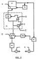
- Figure 2 shows a block diagram of the components of a flow meter according to the present invention.
- FIG. 1 illustrates a typical electrical signal 1 generated as a result of the detection of an ultrasonic wave packet originating from a piezoelectric transducer when stimulated with a single electrical pulse and is representative of the amplitude variations of the detected ultrasonic pulses in that packet with time, t.
- the electrical signal 1 comprises a number of rapidly decaying pulses with amplitudes which alternate about a "zero" level.
- a zero crossing detector that is configured to operate to detect when the signal 1 crosses the zero level, moving from "negative” to "positive”, could possibly detect any one of the five crossing points P1..P5.
- a preset pre-trigger level V may be employed so that, in theory, only the crossing P3 triggers a correct detection.
- Figure 1 also illustrates what may happen in practice.
- the pre-trigger level V
- V the pre-trigger level
- the amplitude of the signal reduces as illustrated by the partial trace 1', for example because of a change in the properties of the medium through which the acoustic signal propagates, then the pre-trigger level will no longer be useable.
- the pre-trigger level is set as shown by V' then a correct determination at P3 might still be expected in the above case.
- any increase in the signal, as illustrated by 1'' for example because of noise, may trigger an incorrect detection at the crossing P2. This would lead to an error in the determination of the arrival of the ultrasonic pulse when using prior art flow meters that incorporate known zero crossing detectors.
- a flow meter according to the present invention is shown schematically at Figure 2.
- a high frequency oscillator 2 is connected to a processor 3 which is in part configured to act as an elapsed time indicator 4.
- the indicator 4 operates in the present example to count the number of pulses generated by the high frequency oscillator 2 in a time interval defined by input start and stop signals. From a knowledge of the count number and the oscillator frequency the elapsed time may be calculated in a manner known from the prior art.
- an electrical signal generator 5 which provides electrical pulses to a piezoelectric crystal 6 for generating an ultrasound signal.
- a second piezoelectric crystal 7 is physically displaced from the crystal 6 and operates to convert incident ultrasound pulses into electrical signals.
- An amplifier 8 is connected between the crystal 7 and a zero crossing detector 9, the output of which detector 9 is connected to the elapsed time indicator 4 of the processor 3.
- a time delay 10 is also provided in operable connection between the signal generator 5 and the zero crossing detector 9.
- the zero crossing detector 9 comprises a control means 11, a comparator 12, an analyser 13 which operate as described below.
- the processor 3 produces a start command signal to the counter 4, the high frequency oscillator 2 and the electrical signal generator 5.
- the counter 4 On receipt of this start signal the counter 4 is primed to receive and count pulses input from the oscillator 2 which itself responds to the start signal by commencing the output of "clock" pulses at a known frequency to the counter 4.
- the start signal from the processor 3 also triggers the production of an electrical pulse from the generator 5.
- the electrical pulse from the generator 5 energises the piezoelectric crystal 6 which then transmits a ultrasound pulse packet of the form generally shown in Figure 1 through a medium the flow of which is to be measured for receipt by the receiving crystal 7.
- This crystal 7 then converts the ultrasound signal to an electrical pulse packet of the same relative amplitude as the ultrasonic pulse packet.
- the electrical pulse packet passes through the amplifier 8 to serve as a currently input electrical pulse packet to the analyser 13, the comparator 12 and the control means 11.
- the control means 11 detects the maximum amplitude of the currently input electrical pulse packet and stores a representation of that maximum amplitude in a memory 14 which representation substitutes an earlier stored representation.
- the substituted earlier stored representation of a maximum amplitude of a previously input electrical pulse packet is retrieved from the memory 14 of the control means 11 before its substitution and is compared within the control means 11 with a pre-trigger level.
- the control means 11 is further configured to control the amplitude of the pre-trigger level in dependence of this comparison in order to maintain a working difference between the two thus compared amplitudes, for example by adjusting the pre-trigger level to remain a predetermined fraction of the earlier stored maximum amplitude that was retrieved from the memory 14.
- the controlled pre-trigger level is then output from the control means 11 to an input of the comparator 12.
- the comparator 12 operates to compare the amplitudes of the pre-trigger level and the currently input electrical pulse packet to detect a crossing of the pre-trigger level by the pulse packet and to output a signal dependent on this detection. This output is used to control the operation of the analyser 13 to prevent a trigger signal being output from the analyser 13 until a crossing of the pre-trigger level is detected by the comparator 12.
- the analyser 13 is configured to determine a zero-point crossing of the currently input electrical pulse packet and to output a trigger signal when such a crossing is detected.
- the trigger signal from analyser 13 passes to the elapsed time indicator 4 of the processor 3 where it acts to stop the indicator 4 counting.
- the processor 3 may be programmed to calculate the elapsed time using the count value from the indicator 4 and the known clock frequency of the high frequency oscillator 2 and from this to calculate the flow of the medium through which the ultrasound signal passed during transmission between the piezoelectric crystals 4, 5 in a manner known in the art.
- the time delay 10 is operably connected with the zero crossing detector 9 and the signal generator 5 and functions to reduce any adverse effects of electrical interference on the operation of the detector 9. This may be achieved as shown in Figure 2.
- the amplified electrical pulse packet is passed from the amplifier 8 into the detector 9 via a automatic switch 15.
- the switch 15 is operably connected to the time delay 10 which closes the switch 15 at a predetermined time after transmission of the electrical pulse by the generator 5 so that substantially only the electrical pulse packet generated by the received acoustic wave can be passed to the zero crossing detector 9. It will be appreciated that the time delay 10 may constructed in several ways and still realise its function.
Landscapes
- Physics & Mathematics (AREA)
- Nonlinear Science (AREA)
- Measuring Volume Flow (AREA)
- Measurement Of Current Or Voltage (AREA)
- Radar Systems Or Details Thereof (AREA)
Applications Claiming Priority (2)
| Application Number | Priority Date | Filing Date | Title |
|---|---|---|---|
| SE9802762 | 1998-08-19 | ||
| SE9802762A SE9802762D0 (sv) | 1998-08-19 | 1998-08-19 | Zero crossing detector and method of determining a zero crossing point |
Publications (3)
| Publication Number | Publication Date |
|---|---|
| EP0981201A2 true EP0981201A2 (fr) | 2000-02-23 |
| EP0981201A3 EP0981201A3 (fr) | 2001-01-03 |
| EP0981201B1 EP0981201B1 (fr) | 2006-11-08 |
Family
ID=20412278
Family Applications (1)
| Application Number | Title | Priority Date | Filing Date |
|---|---|---|---|
| EP99114025A Expired - Lifetime EP0981201B1 (fr) | 1998-08-19 | 1999-07-19 | Détecteur de passages par zéro puis procédé de détermination d'une valeur de passage par zéro |
Country Status (5)
| Country | Link |
|---|---|
| US (1) | US6634240B1 (fr) |
| EP (1) | EP0981201B1 (fr) |
| JP (1) | JP2000065614A (fr) |
| DE (1) | DE69933910T2 (fr) |
| SE (1) | SE9802762D0 (fr) |
Cited By (4)
| Publication number | Priority date | Publication date | Assignee | Title |
|---|---|---|---|---|
| DE10328662B4 (de) * | 2002-06-30 | 2005-09-22 | Siemens Flow Instruments A/S | Verfahren zur Durchflußmessung mittels eines Ultraschall-Durchflußmessers |
| WO2005093379A1 (fr) * | 2004-03-25 | 2005-10-06 | Robert Bosch Gmbh | Detection de passage par zero d'un signal ultrasonore avec valeur seuil variable |
| WO2005114112A3 (fr) * | 2004-05-22 | 2006-04-13 | Bosch Gmbh Robert | Determination de l'instant de reception d'un signal ultrasonore par detection de forme d'impulsion |
| EP1926973B1 (fr) | 2005-09-22 | 2016-09-07 | Endress+Hauser Flowtec AG | Procede pour surveiller un systeme et/ou un processus d'un debitmetre a ultrasons |
Families Citing this family (12)
| Publication number | Priority date | Publication date | Assignee | Title |
|---|---|---|---|---|
| CN1325880C (zh) | 2002-08-05 | 2007-07-11 | 松下电器产业株式会社 | 流量计量装置 |
| US6950768B2 (en) * | 2003-09-08 | 2005-09-27 | Daniel Industries, Inc. | Self-tuning ultrasonic meter |
| US7253600B2 (en) * | 2005-07-19 | 2007-08-07 | Cambridge Analog Technology, Llc | Constant slope ramp circuits for sample-data circuits |
| US9146259B2 (en) | 2011-04-19 | 2015-09-29 | Schneider Electric It Corporation | Smart current transformers |
| WO2013154563A1 (fr) * | 2012-04-12 | 2013-10-17 | Schneider Electric It Corporation | Système et procédé de détection d'un courant de circuit de dérivation |
| CN104412113B (zh) | 2012-04-25 | 2018-04-20 | 施耐德电气It公司 | 电流监测装置 |
| WO2014105018A2 (fr) | 2012-12-27 | 2014-07-03 | Schneider Electric USA, Inc. | Wattmètre équipé de capteur de courant et de phase |
| US9973036B2 (en) | 2013-12-31 | 2018-05-15 | Schneider Electric It Corporation | Automatic sub-millisecond clock synchronization |
| US10801868B2 (en) * | 2014-06-10 | 2020-10-13 | Texas Instruments Incorporated | Extended range ADC flow meter |
| JP7111533B2 (ja) * | 2018-07-12 | 2022-08-02 | アズビル株式会社 | ゼロ点検出装置 |
| EP3657206A1 (fr) | 2018-11-20 | 2020-05-27 | ams AG | Procédé de détection de durée de vol, convertisseur de durée de vol, débitmètre à ultrasons et dispositif optique |
| US11359950B2 (en) * | 2019-12-10 | 2022-06-14 | Johnson Controls Tyco IP Holdings LLP | Reduced length valve assembly with ultrasonic flow sensor |
Citations (2)
| Publication number | Priority date | Publication date | Assignee | Title |
|---|---|---|---|---|
| US4538469A (en) * | 1983-07-29 | 1985-09-03 | Panametrics, Inc. | Integrated threshold arming method and apparatus |
| EP0185133A2 (fr) * | 1984-12-21 | 1986-06-25 | Institut Dr. Friedrich Förster Prüfgerätebau GmbH & Co. KG | Procédé et dispositif pour déterminer avec précision l'intervalle de temps entre deux impulsions électriques |
Family Cites Families (11)
| Publication number | Priority date | Publication date | Assignee | Title |
|---|---|---|---|---|
| FR2077827A1 (fr) * | 1970-02-17 | 1971-11-05 | Thomson Csf | |
| US4080574A (en) * | 1974-01-31 | 1978-03-21 | United Kingdom Atomic Energy Authority | Apparatus for providing time reference signals |
| US4022058A (en) * | 1975-08-07 | 1977-05-10 | Brown Alvin E | Apparatus for determining the arrival time of alternating signals |
| US4515021A (en) * | 1983-07-29 | 1985-05-07 | Panametrics, Inc. | Intervalometer time measurement apparatus and method |
| US4527433A (en) * | 1983-10-25 | 1985-07-09 | General Motors Corporation | Method and apparatus for measuring fluid flow |
| DK0452531T3 (da) * | 1990-04-20 | 1995-06-19 | Siemens Ag | Fremgangsmåde til løbstidsmåling af et elektrisk signal |
| NZ243293A (en) * | 1991-06-25 | 1995-03-28 | Commw Scient Ind Res Org | Fluid flow meter: time of travel of acoustic wave packet through fluid |
| US5247826B1 (en) | 1992-11-12 | 1995-07-18 | Devilbiss Health Care Inc | Gas concentration and/or flow sensor |
| DE4318690A1 (de) | 1993-06-04 | 1995-01-05 | Ndd Medizintechnik Gmbh | Verfahren zur Messung der Molmasse von Gasen oder Gasgemischen und Vorrichtung zur Durchführung dieses Verfahrens |
| US5814737A (en) * | 1996-10-04 | 1998-09-29 | Dieterich Technology Holding Corp. | Apparatus and method of detecting an ultrasonic signal |
| US5639971A (en) | 1996-10-04 | 1997-06-17 | Dieterich Technology Holding Corp. | Method and apparatus for detecting a signal |
-
1998
- 1998-08-19 SE SE9802762A patent/SE9802762D0/xx unknown
-
1999
- 1999-07-19 EP EP99114025A patent/EP0981201B1/fr not_active Expired - Lifetime
- 1999-07-19 DE DE69933910T patent/DE69933910T2/de not_active Expired - Lifetime
- 1999-08-18 JP JP11231638A patent/JP2000065614A/ja active Pending
- 1999-08-19 US US09/377,133 patent/US6634240B1/en not_active Expired - Lifetime
Patent Citations (2)
| Publication number | Priority date | Publication date | Assignee | Title |
|---|---|---|---|---|
| US4538469A (en) * | 1983-07-29 | 1985-09-03 | Panametrics, Inc. | Integrated threshold arming method and apparatus |
| EP0185133A2 (fr) * | 1984-12-21 | 1986-06-25 | Institut Dr. Friedrich Förster Prüfgerätebau GmbH & Co. KG | Procédé et dispositif pour déterminer avec précision l'intervalle de temps entre deux impulsions électriques |
Cited By (6)
| Publication number | Priority date | Publication date | Assignee | Title |
|---|---|---|---|---|
| DE10328662B4 (de) * | 2002-06-30 | 2005-09-22 | Siemens Flow Instruments A/S | Verfahren zur Durchflußmessung mittels eines Ultraschall-Durchflußmessers |
| WO2005093379A1 (fr) * | 2004-03-25 | 2005-10-06 | Robert Bosch Gmbh | Detection de passage par zero d'un signal ultrasonore avec valeur seuil variable |
| US7543508B2 (en) | 2004-03-25 | 2009-06-09 | Robert Bosch Gmbh | Zero crossing detection of an ultrasonic signal with variable threshold value |
| WO2005114112A3 (fr) * | 2004-05-22 | 2006-04-13 | Bosch Gmbh Robert | Determination de l'instant de reception d'un signal ultrasonore par detection de forme d'impulsion |
| US8744785B2 (en) | 2004-05-22 | 2014-06-03 | Robert Bosch Gmbh | Determination of a reception time of an ultrasonic signal by means of pulse shape detection |
| EP1926973B1 (fr) | 2005-09-22 | 2016-09-07 | Endress+Hauser Flowtec AG | Procede pour surveiller un systeme et/ou un processus d'un debitmetre a ultrasons |
Also Published As
| Publication number | Publication date |
|---|---|
| SE9802762D0 (sv) | 1998-08-19 |
| EP0981201A3 (fr) | 2001-01-03 |
| EP0981201B1 (fr) | 2006-11-08 |
| JP2000065614A (ja) | 2000-03-03 |
| DE69933910T2 (de) | 2007-05-16 |
| DE69933910D1 (de) | 2006-12-21 |
| US6634240B1 (en) | 2003-10-21 |
Similar Documents
| Publication | Publication Date | Title |
|---|---|---|
| EP0981201B1 (fr) | Détecteur de passages par zéro puis procédé de détermination d'une valeur de passage par zéro | |
| US5796009A (en) | Method for measuring in a fluid with the aid of sing-around technique | |
| US4607520A (en) | Method and apparatus for detecting discontinuities in a fluid stream | |
| US6631639B1 (en) | System and method of non-invasive discreet, continuous and multi-point level liquid sensing using flexural waves | |
| US5269188A (en) | Continuous self test time gate ultrasonic sensor and method | |
| US4557148A (en) | Ultrasonic flowmeter | |
| JPH06148003A (ja) | 超音波を用いた温度測定装置 | |
| EP0932029B1 (fr) | Débitmètre acoustique | |
| EP0596966A4 (en) | Time gate ultrasonic sensor and method. | |
| EP0142733A2 (fr) | Télémètre à ultrasons | |
| US6786633B2 (en) | Method and arrangement for acoustically determining a fluid temperature | |
| JP4760115B2 (ja) | 流体の流れ計測装置 | |
| JPH1151725A (ja) | 超音波流量計 | |
| JP3419341B2 (ja) | 流量計測装置 | |
| JPH0758179B2 (ja) | クラッド厚さ測定装置 | |
| JP2771570B2 (ja) | 超音波検知器 | |
| JPH0117090B2 (fr) | ||
| JPH0882673A (ja) | 超音波式距離測定装置 | |
| JPH1151726A (ja) | 伝搬時間計測装置、超音波式流量計、伝搬時間計測方法及び超音波式流量計の制御方法 | |
| JPS6076677A (ja) | 超音波距離検出装置 | |
| JPS6050287B2 (ja) | 超音波測定装置 | |
| JPH053526B2 (fr) | ||
| JPS63236985A (ja) | 超音波距離測定装置 | |
| JPS6116947B2 (fr) | ||
| JPS6367153B2 (fr) |
Legal Events
| Date | Code | Title | Description |
|---|---|---|---|
| PUAI | Public reference made under article 153(3) epc to a published international application that has entered the european phase |
Free format text: ORIGINAL CODE: 0009012 |
|
| AK | Designated contracting states |
Kind code of ref document: A2 Designated state(s): DE FR |
|
| AX | Request for extension of the european patent |
Free format text: AL;LT;LV;MK;RO;SI |
|
| PUAL | Search report despatched |
Free format text: ORIGINAL CODE: 0009013 |
|
| AK | Designated contracting states |
Kind code of ref document: A3 Designated state(s): AT BE CH CY DE DK ES FI FR GB GR IE IT LI LU MC NL PT SE |
|
| AX | Request for extension of the european patent |
Free format text: AL;LT;LV;MK;RO;SI |
|
| RIC1 | Information provided on ipc code assigned before grant |
Free format text: 7H 03K 5/1536 A, 7G 01F 1/66 B |
|
| 17P | Request for examination filed |
Effective date: 20010419 |
|
| AKX | Designation fees paid |
Free format text: DE FR |
|
| RAP1 | Party data changed (applicant data changed or rights of an application transferred) |
Owner name: MAQUET CRITICAL CARE AB |
|
| GRAP | Despatch of communication of intention to grant a patent |
Free format text: ORIGINAL CODE: EPIDOSNIGR1 |
|
| GRAS | Grant fee paid |
Free format text: ORIGINAL CODE: EPIDOSNIGR3 |
|
| GRAA | (expected) grant |
Free format text: ORIGINAL CODE: 0009210 |
|
| AK | Designated contracting states |
Kind code of ref document: B1 Designated state(s): DE FR |
|
| REF | Corresponds to: |
Ref document number: 69933910 Country of ref document: DE Date of ref document: 20061221 Kind code of ref document: P |
|
| ET | Fr: translation filed | ||
| PLBE | No opposition filed within time limit |
Free format text: ORIGINAL CODE: 0009261 |
|
| STAA | Information on the status of an ep patent application or granted ep patent |
Free format text: STATUS: NO OPPOSITION FILED WITHIN TIME LIMIT |
|
| 26N | No opposition filed |
Effective date: 20070809 |
|
| REG | Reference to a national code |
Ref country code: DE Ref legal event code: R082 Ref document number: 69933910 Country of ref document: DE Representative=s name: SCHAUMBURG UND PARTNER PATENTANWAELTE MBB, DE Ref country code: DE Ref legal event code: R082 Ref document number: 69933910 Country of ref document: DE Representative=s name: SCHAUMBURG & PARTNER PATENTANWAELTE GBR, DE |
|
| REG | Reference to a national code |
Ref country code: FR Ref legal event code: PLFP Year of fee payment: 18 |
|
| PGFP | Annual fee paid to national office [announced via postgrant information from national office to epo] |
Ref country code: FR Payment date: 20160613 Year of fee payment: 18 |
|
| REG | Reference to a national code |
Ref country code: FR Ref legal event code: ST Effective date: 20180330 |
|
| PG25 | Lapsed in a contracting state [announced via postgrant information from national office to epo] |
Ref country code: FR Free format text: LAPSE BECAUSE OF NON-PAYMENT OF DUE FEES Effective date: 20170731 |
|
| PGFP | Annual fee paid to national office [announced via postgrant information from national office to epo] |
Ref country code: DE Payment date: 20180703 Year of fee payment: 20 |
|
| REG | Reference to a national code |
Ref country code: DE Ref legal event code: R071 Ref document number: 69933910 Country of ref document: DE |