EP0981035B1 - Heat exchanger for exhaust gases - Google Patents
Heat exchanger for exhaust gases Download PDFInfo
- Publication number
- EP0981035B1 EP0981035B1 EP99115443A EP99115443A EP0981035B1 EP 0981035 B1 EP0981035 B1 EP 0981035B1 EP 99115443 A EP99115443 A EP 99115443A EP 99115443 A EP99115443 A EP 99115443A EP 0981035 B1 EP0981035 B1 EP 0981035B1
- Authority
- EP
- European Patent Office
- Prior art keywords
- heat exchanger
- exhaust
- flat tubes
- gas
- flow ducts
- Prior art date
- Legal status (The legal status is an assumption and is not a legal conclusion. Google has not performed a legal analysis and makes no representation as to the accuracy of the status listed.)
- Expired - Lifetime
Links
Images


Classifications
-
- F—MECHANICAL ENGINEERING; LIGHTING; HEATING; WEAPONS; BLASTING
- F28—HEAT EXCHANGE IN GENERAL
- F28D—HEAT-EXCHANGE APPARATUS, NOT PROVIDED FOR IN ANOTHER SUBCLASS, IN WHICH THE HEAT-EXCHANGE MEDIA DO NOT COME INTO DIRECT CONTACT
- F28D9/00—Heat-exchange apparatus having stationary plate-like or laminated conduit assemblies for both heat-exchange media, the media being in contact with different sides of a conduit wall
- F28D9/0031—Heat-exchange apparatus having stationary plate-like or laminated conduit assemblies for both heat-exchange media, the media being in contact with different sides of a conduit wall the conduits for one heat-exchange medium being formed by paired plates touching each other
- F28D9/0043—Heat-exchange apparatus having stationary plate-like or laminated conduit assemblies for both heat-exchange media, the media being in contact with different sides of a conduit wall the conduits for one heat-exchange medium being formed by paired plates touching each other the plates having openings therein for circulation of at least one heat-exchange medium from one conduit to another
-
- F—MECHANICAL ENGINEERING; LIGHTING; HEATING; WEAPONS; BLASTING
- F28—HEAT EXCHANGE IN GENERAL
- F28D—HEAT-EXCHANGE APPARATUS, NOT PROVIDED FOR IN ANOTHER SUBCLASS, IN WHICH THE HEAT-EXCHANGE MEDIA DO NOT COME INTO DIRECT CONTACT
- F28D7/00—Heat-exchange apparatus having stationary tubular conduit assemblies for both heat-exchange media, the media being in contact with different sides of a conduit wall
- F28D7/0008—Heat-exchange apparatus having stationary tubular conduit assemblies for both heat-exchange media, the media being in contact with different sides of a conduit wall the conduits for one medium being in heat conductive contact with the conduits for the other medium
- F28D7/0025—Heat-exchange apparatus having stationary tubular conduit assemblies for both heat-exchange media, the media being in contact with different sides of a conduit wall the conduits for one medium being in heat conductive contact with the conduits for the other medium the conduits for one medium or the conduits for both media being flat tubes or arrays of tubes
-
- F—MECHANICAL ENGINEERING; LIGHTING; HEATING; WEAPONS; BLASTING
- F28—HEAT EXCHANGE IN GENERAL
- F28D—HEAT-EXCHANGE APPARATUS, NOT PROVIDED FOR IN ANOTHER SUBCLASS, IN WHICH THE HEAT-EXCHANGE MEDIA DO NOT COME INTO DIRECT CONTACT
- F28D9/00—Heat-exchange apparatus having stationary plate-like or laminated conduit assemblies for both heat-exchange media, the media being in contact with different sides of a conduit wall
- F28D9/0031—Heat-exchange apparatus having stationary plate-like or laminated conduit assemblies for both heat-exchange media, the media being in contact with different sides of a conduit wall the conduits for one heat-exchange medium being formed by paired plates touching each other
- F28D9/0037—Heat-exchange apparatus having stationary plate-like or laminated conduit assemblies for both heat-exchange media, the media being in contact with different sides of a conduit wall the conduits for one heat-exchange medium being formed by paired plates touching each other the conduits for the other heat-exchange medium also being formed by paired plates touching each other
-
- F—MECHANICAL ENGINEERING; LIGHTING; HEATING; WEAPONS; BLASTING
- F28—HEAT EXCHANGE IN GENERAL
- F28D—HEAT-EXCHANGE APPARATUS, NOT PROVIDED FOR IN ANOTHER SUBCLASS, IN WHICH THE HEAT-EXCHANGE MEDIA DO NOT COME INTO DIRECT CONTACT
- F28D21/00—Heat-exchange apparatus not covered by any of the groups F28D1/00 - F28D20/00
- F28D21/0001—Recuperative heat exchangers
- F28D21/0003—Recuperative heat exchangers the heat being recuperated from exhaust gases
-
- F—MECHANICAL ENGINEERING; LIGHTING; HEATING; WEAPONS; BLASTING
- F28—HEAT EXCHANGE IN GENERAL
- F28F—DETAILS OF HEAT-EXCHANGE AND HEAT-TRANSFER APPARATUS, OF GENERAL APPLICATION
- F28F2250/00—Arrangements for modifying the flow of the heat exchange media, e.g. flow guiding means; Particular flow patterns
- F28F2250/10—Particular pattern of flow of the heat exchange media
- F28F2250/104—Particular pattern of flow of the heat exchange media with parallel flow
-
- F—MECHANICAL ENGINEERING; LIGHTING; HEATING; WEAPONS; BLASTING
- F28—HEAT EXCHANGE IN GENERAL
- F28F—DETAILS OF HEAT-EXCHANGE AND HEAT-TRANSFER APPARATUS, OF GENERAL APPLICATION
- F28F2250/00—Arrangements for modifying the flow of the heat exchange media, e.g. flow guiding means; Particular flow patterns
- F28F2250/10—Particular pattern of flow of the heat exchange media
- F28F2250/108—Particular pattern of flow of the heat exchange media with combined cross flow and parallel flow
Definitions
- the invention relates to an exhaust gas heat exchanger with pairs of bowl-shaped Heat exchanger plates; forms each pair of bowl-shaped heat exchanger plates a flow channel for cooling water by using the peripheral flange are mirrored assembled and connected so that the edge flange of the a heat exchanger plate on one side and the edge flange on the other Heat exchanger plate is directed to the opposite side, as well as with openings in the heat exchanger plates, which lie on a common line to form the collecting and distribution channel for the cooling water and with between the above-mentioned flow channels arranged further flow channels for the exhaust gas.
- This exhaust gas heat exchanger is known from EP 677 715.
- the known exhaust gas heat exchanger can be regarded as disadvantageous because breakthroughs on the exhaust side caused by corrosion lead to the mixing of the exhaust gas with the cooling water. Since the exhaust gases contain very aggressive substances, the possibility of rusting through is not far away. Therefore, the heat exchanger plates, the corrugated fins and the connecting pieces are made of stainless steel in the document mentioned, but this increases the costs. In addition, despite this measure, there is no guarantee that mixing will not happen, since even the stainless steel plates, if they are not the highest quality, can be attacked, at least in the vicinity of the soldered connections. Especially since there is a constant effort to reduce the sheet thickness of the heat exchanger plates.
- the required housing which surrounds the heat exchanger.
- the exhaust gas heat exchanger is constructed in the so-called document in a so-called rod-plate construction and has an outer housing. This otherwise advantageous construction has the disadvantage that the number of individual parts and the number and length of the soldered connections are quite large, which increases the risk that soldering errors can occur.
- the object of the invention is to further reduce the manufacturing costs in the exhaust gas heat exchanger specified in the preamble and also to ensure greater security against mixing of the exhaust gas with the cooling water, with at the same time low pressure loss on the exhaust side.
- the solution according to the invention results from the characterizing part of patent claim 1.
- the problem is solved by the skillful combination of features which may be known individually in heat exchanger construction, the inventors having recognized that their novel interaction leads to an inventive exhaust gas heat exchanger in which the exhaust gas is cooled with liquid.
- the exhaust gas heat exchanger is designed in a housingless design, that the flow channels formed from shell-shaped heat exchanger plates are provided for the cooling water and that the flow channels for the exhaust gas arranged therebetween are approximately straight flat tubes which open at opposite ends in tube sheets to which the Exhaust pipe is connected.
- the tube sheets have a diameter that is at least partially larger than the subsequent cross-sectional dimension of the heat exchanger.
- the tube sheets are preferably circular parts, as a result of which the production and connection of the likewise round exhaust pipe can be carried out more easily.
- the flue gas pipe can be connected to the heat exchanger using screws, clamps or clamping rings.
- At least one type of flow channel has a corrugated or similarly structured surface. The corrugated surface structure sufficiently ensures that, in the event of rusting, the exhaust gas can escape to the atmosphere and not easily get into the cooling water.
- the pressure loss on the exhaust side is extremely low because the associated flow channels have no deflections and because the tube sheets are kept so large that this requirement can be met. Furthermore, the distributor and the collecting space for the cooling water are arranged in projecting areas of the bowl-shaped heat exchanger plates, which are outside the cross section of the flat tubes. This also makes a contribution to reducing the pressure loss on the exhaust side, because the distributor and collection space are therefore not in the flow area of the exhaust gases and do not impede their flow.
- the manufacturing costs are reduced in that the water-cooled exhaust gas heat exchanger according to the invention only has to be made of stainless steel on the exhaust side - that is, the flat tubes and the tube sheets - while all other parts can be made of aluminum.
- the water-cooled exhaust gas heat exchanger from EP 677 715 is made entirely of stainless steel.
- the proposed exhaust gas heat exchanger therefore also has a lower weight. Furthermore, a contribution to lowering the manufacturing costs can be seen in the fact that the water-cooled exhaust gas heat exchanger, as stated above, is provided in a housing-free design.
- the external flow channels are cooling water channels, so that the radiant heat of the heat exchanger is reduced, which is not insignificant in exhaust gas heat exchangers because of the high exhaust gas temperatures.
- the bowl-shaped heat exchanger plates, which form the flow channels for the cooling water have inward corrugated support knobs in their corrugated surface, which are soldered at their apex to the same support knobs of the adjacent heat exchanger plate.
- the flat tubes that carry the exhaust gas can either be drawn tubes or flat tubes welded with a longitudinal seam, or they can be formed from two half-shells that are soldered together on the peripheral edge flange. Punched or rolled inner inserts can be arranged in the flat tubes, which are soldered to the tubes in order to promote heat exchange and to increase the stability.
- the wall of the flat tubes has a wave-like structure.
- the wave peaks and valleys run in the longitudinal direction of the flat tubes.
- there are projecting and angled sections on their edge flange which interlock and serve to correctly position two half-shells to form a flat tube. These sections are comparable to those on the edge flange of the heat exchanger plates. Openings are punched out in the tube sheets, which are adapted to the cross section of the flat tubes and which have passages which are either directed towards the exhaust gas line or towards the interior of the heat exchanger.
- FIG. 5 shows the view from the direction of the clamping ring 26 of the embodiment from FIGS. 1, 2 and 4.
- inner inserts 24 in the flat tubes 8 have been completely dispensed with.
- the walls of the flat tubes 8 consisting of two half-shells 8/1 and 8/2 were formed with a distinct wave-like structure 22.
- the wave crests and the wave troughs here run in the longitudinal direction of the flat tubes 8 or the flow channels 14.
- the heat exchanger plates 6 are preferably also included formed a smooth surface, apart from the embossed knobs 11.
- This embodiment is particularly suitable for exhaust gas heat exchangers because the risk of clogging of the flat tubes 8 by deposits is significantly lower.
- FIG. 7 shows the view belonging to the exemplary embodiment in FIG. 6 from the direction of the clamping ring 26.
- the longitudinal wave-like structure 22 of the flow channels 14 is also evident from this illustration.
- the longitudinal section in FIG. 8 also belonging to this embodiment shows that the undulating structure 22 ends in front of the tube sheet 13.
- the passages 25 on the tube plate 13 were made towards the heat exchanger and the flat tubes 8 were plugged with their ends onto these passages 25
- FIG. 8 shows another connection to the exhaust pipe, not shown.
- FIG. 9 can be interpreted as a cross section in FIG. 3. It differs from FIG. 4 in that welded or drawn flat tubes 8 have been used here. Furthermore, the attachment was selected with the aid of a connecting flange 27, as is also shown in FIG. 3. 10 differs from the exemplary embodiment in FIG. 9 in that in FIG. 10 the passages 25 on the tube sheet 13 are directed towards the exhaust gas line, while in FIG. 9 the passages 25 point towards the heat exchanger.
- FIG. 11 shows an exemplary embodiment in which the overhanging regions 7, in which the collecting and distribution spaces 20, 21 are arranged, are located on opposite sides of the heat exchanger. Therefore, two different types of heat exchanger plates 6 must be used here.
- Fig. 12 shows a partial longitudinal section, similar to Fig. 8, but in which the heat exchanger plates 6 have a corrugated surface structure 22 in order to achieve greater security against mixing of exhaust gas and cooling water.
- the flat tubes 8 have also been used in the passages 25 of the tube sheet 13.
Landscapes
- Engineering & Computer Science (AREA)
- Physics & Mathematics (AREA)
- Thermal Sciences (AREA)
- Mechanical Engineering (AREA)
- General Engineering & Computer Science (AREA)
- Heat-Exchange Devices With Radiators And Conduit Assemblies (AREA)
- Exhaust Gas After Treatment (AREA)
- Gas Separation By Absorption (AREA)
- Separation By Low-Temperature Treatments (AREA)
Abstract
Description
Die Erfindung betrifft einen Abgaswärmetauscher mit Paaren schalenförmiger Wärmetauscherplatten; jedes Paar schalenförmiger Wärmetauscherplatten bildet einen Strömungskanal für Kühlwasser, indem sie am umlaufenden Randflansch spiegelbildlich so zusammengefügt und verbunden sind, daß der Randflansch der einen Wärmetauscherplatte nach einer Seite und der Randflansch der anderen Wärmetauscherplatte zur entgegengesetzten Seite gerichtet ist, sowie mit Öffnungen in den Wärmetauscherplatten, die auf einer gemeinsamen Linie liegen, um den Sammel-und den Verteilerkanal für das Kühlwasser zu bilden und mit zwischen den erwähnten Strömungskanälen angeordneten weiteren Strömungskanälen für das Abgas.The invention relates to an exhaust gas heat exchanger with pairs of bowl-shaped Heat exchanger plates; forms each pair of bowl-shaped heat exchanger plates a flow channel for cooling water by using the peripheral flange are mirrored assembled and connected so that the edge flange of the a heat exchanger plate on one side and the edge flange on the other Heat exchanger plate is directed to the opposite side, as well as with openings in the heat exchanger plates, which lie on a common line to form the collecting and distribution channel for the cooling water and with between the above-mentioned flow channels arranged further flow channels for the exhaust gas.
Dieser Abgaswärmetauscher ist aus dem EP 677 715 bekannt. Der bekannte Abgaswärmetauscher
kann insofern als nachteilig angesehen werden, weil durch
Korrosion verursachte Durchbrüche auf der Abgasseite zum Vermischen des Abgases
mit dem Kühlwasser führen. Da die Abgase sehr aggressive Stoffe enthalten,
ist die Möglichkeit der Durchrostung nicht weit entfernt. Deshalb sind in dem
genannten Dokument die Wärmetauscherplatten, die Wellrippen und die Anschlußstutzen
aus Edelstahl gefertigt, was jedoch die Kosten erhöht. Hinzu
kommt, daß trotz dieser Maßnahme keine Gewähr dafür besteht, daß nicht doch
eine Vermischung passiert, da selbst die Edelstahlbieche, wenn es nicht die
hochwertigsten sind, zumindest in der Nähe der Lötverbindungen, angegriffen
werden können. Zumal man ständig bestrebt ist, die Blechdicken der Wärmetauscherplatten
zu reduzieren. Ferner werden Kosten und Gewicht durch das erforderliche
Gehäuse erhöht, welches den Wärmetauscher umgibt. Darüber hinaus
ergeben sich fertigungstechnische Schwierigkeit beim korrekten Positionieren der
beiden schalenförmigen Wärmetauscherplatten zueinander.
Wenn als Kühlmittel das Kühlwasser des Motors verwendet werden soll, ist der
Abgaswärmetauscher in dem genannten Dokument in sogenannter Stab-Platten-Bauweise
aufgebaut und besitzt ein äußeres Gehäuse. Diese ansonsten vorteilhafte
Bauweise hat den Nachteil, daß die Anzahl der Einzelteile und die Anzahl
und Länge der Lötverbindungen recht groß sind, wodurch sich das Risiko erhöht,
daß Lötfehler auftreten können. This exhaust gas heat exchanger is known from EP 677 715. The known exhaust gas heat exchanger can be regarded as disadvantageous because breakthroughs on the exhaust side caused by corrosion lead to the mixing of the exhaust gas with the cooling water. Since the exhaust gases contain very aggressive substances, the possibility of rusting through is not far away. Therefore, the heat exchanger plates, the corrugated fins and the connecting pieces are made of stainless steel in the document mentioned, but this increases the costs. In addition, despite this measure, there is no guarantee that mixing will not happen, since even the stainless steel plates, if they are not the highest quality, can be attacked, at least in the vicinity of the soldered connections. Especially since there is a constant effort to reduce the sheet thickness of the heat exchanger plates. Furthermore, costs and weight are increased by the required housing, which surrounds the heat exchanger. In addition, there are manufacturing difficulties in correctly positioning the two bowl-shaped heat exchanger plates relative to one another.
If the cooling water of the engine is to be used as the coolant, the exhaust gas heat exchanger is constructed in the so-called document in a so-called rod-plate construction and has an outer housing. This otherwise advantageous construction has the disadvantage that the number of individual parts and the number and length of the soldered connections are quite large, which increases the risk that soldering errors can occur.
Beispielsweise aus DE 44 03 144 C2 ist es außerdem bekannt, gehäuselose Plattenwärmetauscher, (Ölkühler) die als vermischungsfrei bezeichnet werden können, quasi in Mischbauweise zu fertigen, bei der die eine Art Rohrplatten in Stab-Platten-Bauweise und die andere Art der Rohrplatten aus Halbschalen gefertigt sind. Hier ist jedoch die Vermischungsfreiheit durch die Anordnung einer zusätzlichen Sicherheitstrennwand erzielt worden, wodurch das Gesamtgewicht relativ hoch ist. Ferner würde dieser Wärmetauscher als Abgaswärmetauscher einen zu großen Druckverlust auf der Abgasseite erzeugen, der seine Ursache in der Vielzahl der Umlenkungen hat. Gerade der Druckverlust auf der Abgasseite ist besonders nachteilig, weil das gekühlte Abgas mit höchstmöglichem Druck dem nachgeschalteten Turbolader zugeführt werden sollte.From DE 44 03 144 C2, for example, it is also known to be without a housing Plate heat exchangers (oil coolers) which are described as non-mixing can produce, so to speak, in mixed construction, in which the one kind of tube plates in Rod-plate construction and the other type of tube plates made from half-shells are. However, here is the freedom of mixing by arranging one Additional security partition has been achieved, reducing the overall weight is relatively high. Furthermore, this heat exchanger would act as an exhaust gas heat exchanger generate too great a pressure loss on the exhaust side, which is caused in of the multitude of diversions. The pressure loss on the exhaust side is just particularly disadvantageous because the cooled exhaust gas with the highest possible pressure downstream turbocharger should be fed.
Der Nachteil des zu hohen Druckverlustes muß auch dem aus DE 296 16 354 U1 bekannten flüssigkeitsgekühlten Abgaswärmetauscher zugeordnet werden.The disadvantage of the excessive pressure loss must also be that from DE 296 16 354 U1 known liquid-cooled exhaust gas heat exchanger can be assigned.
Die Aufgabe der Erfindung besteht darin, bei dem im Oberbegriff angegebenen
Abgaswärmetauscher die Fertigungskosten weiter zu senken und außerdem eine
höhere Sicherheit gegen Vermischen des Abgases mit dem Kühlwasser zu
gewährleisten, bei gleichzeitig geringem Druckverlust auf der Abgasseite.
Die erfindungsgemäße Lösung ergibt sich aus dem Kennzeichen des Patentanspruchs
1.
Die Lösung der Aufgabenstellung erfolgt durch die geschickte Kombination von im
Wärmetauscherbau möglicherweise einzeln bekannter Merkmale, wobei die Erfinder
erkannt haben, daß deren neuartiges Zusammenwirken zu einem erfinderischen
Abgaswärmetauscher führt, bei dem das Abgas mit Flüssigkeit gekühlt
wird.The object of the invention is to further reduce the manufacturing costs in the exhaust gas heat exchanger specified in the preamble and also to ensure greater security against mixing of the exhaust gas with the cooling water, with at the same time low pressure loss on the exhaust side.
The solution according to the invention results from the characterizing part of patent claim 1.
The problem is solved by the skillful combination of features which may be known individually in heat exchanger construction, the inventors having recognized that their novel interaction leads to an inventive exhaust gas heat exchanger in which the exhaust gas is cooled with liquid.
Es wird vorgeschlagen, daß der Abgaswärmetauscher in gehäuseloser Bauweise
ausgeführt ist, daß die aus schalenförmigen Wärmetauscherplatten gebildeten
Strömungskanäle für das Kühlwasser vorgesehen sind und daß die dazwischen
angeordneten Strömungskanäle für das Abgas etwa gerade Flachrohre sind, die
an gegenüberliegenden Enden in Rohrböden münden, an die die Abgasleitung
angeschlossen ist.
Die Rohrböden haben einen Durchmesser, der zumindest partiell größer ist als die
sich anschließende Querschnittsabmessung des Wärmetauschers. Die
Rohrböden sind vorzugsweise kreisrunde Teile, wodurch die Herstellung und
auch der Anschluß der ebenfalls runden Abgasleitung einfacher erfolgen kann.
Der Anschluß der Abgasleitung an den Wärmetauscher kann mittels Schrauben,
Klammern oder Spannringen erfolgen.
Mindestens eine Art der Strömungskanäle weist eine gewellte oder ähnlich strukturierte
Oberfläche auf. Die gewellte Oberflächenstruktur sorgt in hinreichender
Weise dafür, daß im Falle einer Durchrostung das Abgas zur Atmosphäre hin
austreten kann und nicht so einfach in das Kühlwasser gelangt.It is proposed that the exhaust gas heat exchanger is designed in a housingless design, that the flow channels formed from shell-shaped heat exchanger plates are provided for the cooling water and that the flow channels for the exhaust gas arranged therebetween are approximately straight flat tubes which open at opposite ends in tube sheets to which the Exhaust pipe is connected.
The tube sheets have a diameter that is at least partially larger than the subsequent cross-sectional dimension of the heat exchanger. The tube sheets are preferably circular parts, as a result of which the production and connection of the likewise round exhaust pipe can be carried out more easily.
The flue gas pipe can be connected to the heat exchanger using screws, clamps or clamping rings.
At least one type of flow channel has a corrugated or similarly structured surface. The corrugated surface structure sufficiently ensures that, in the event of rusting, the exhaust gas can escape to the atmosphere and not easily get into the cooling water.
Der Druckverlust auf der Abgasseite ist äußerst gering, weil die zugehörigen
Strömungskanäle keine Umlenkungen aufweisen und weil auch die Rohrböden so
groß gehalten sind, daß dieser Vorgabe entsprochen werden kann. Ferner sind
der Verteiler - und der Sammelraum für das Kühlwasser in überkragenden Bereichen
der schalenförmigen Wärmetauscherplatten angeordnet, die sich außerhalb
des Querschnittes der Flachrohre befinden. Dadurch wird ebenfalls ein Beitrag zur
Senkung des Druckverlustes auf der Abgasseite geleistet, denn dadurch befinden
sich der Verteiler-und der Sammelraum nicht im Strömungsbereich der Abgase
und behindern nicht deren Strömung.
Die Fertigungskosten werden dadurch gesenkt, daß der erfindungsgemäße wassergekühlte
Abgaswärmetauscher lediglich auf der Abgasseite - also die Flachrohre
und die Rohrböden - aus Edelstahl bestehen muß, während alle anderen
Teile aus Aluminium hergestellt sein können. Der wassergekühlte Abgaswärmetauscher
aus dem EP 677 715 besteht hingegen vollständig aus Edelstahl.
Der vorgeschlagene Abgaswärmerauscher weist deshalb auch ein geringeres
Gewicht auf.
Ferner kann ein Beitrag zur Senkung der Fertigungskosten darin gesehen werden,
daß der wassergekühlte Abgaswärmetauscher, wie oben angegeben, in gehäuseloser
Ausführung vorgesehen ist. Die außenliegenden Strömungskanäle
sind Kühlwasserkanäle, so daß die Strahlungswärme des Wärmetauschers reduziert
ist, was bei Abgaswärmetauschern wegen der hohen Abgastemperaturen
nicht unwesentlich ist.
Die schalenförmigen Wärmetauscherplatten, die die Strömungskanäle für das
Kühlwasser bilden, besitzen in ihrer gewellten Oberfläche nach innen gerichtete
Abstütznoppen, die an ihrem Scheitelpunkt mit ebensolchen Abstütznoppen der
benachbarten Wärmetauscherplatte verlötet sind. Diese an sich bekannte Ausbildung
sorgt für besseren Wärmeübergang und für höhere Festigkeit des Abgaswärmetauschers.
Ein weiteres vorteilhaftes Merkmal der Wärmetauscherplatten besteht darin, daß
am Randflansch in gewissen Abständen überstehende und abgewinkelte Abschnitte
vorgesehen sind, mit deren Hilfe sich jeweils zwei Wärmetauscherplatten
zueinander positionieren lassen, d. h. sie können nicht verrutschen. Es werden
deshalb auch keine Hilfsvorrichtungen beim Stapeln und beim Vorbereiten zum
Löten erforderlich.
Die Flachrohre, die das Abgas führen, können sowohl gezogene oder mit einer
Längsnaht geschweißte Flachrohre sein, als auch aus zwei Halbschalen gebildet
sein, die am umlaufenden Randflansch miteinander verlötet sind. In den Flachrohren
können gestanzte oder gewalzte Inneneinsätze angeordnet sein, die mit
den Rohren verlötet sind, um den Wärmeaustausch zu fördern und die Stabilität
zu erhöhen. Eine Ausführungsform verzichtet jedoch völlig auf solche Inneneinsätze,
um den Druckverlust weiter zu reduzieren. Dafür besitzt die Wandung der
Flachrohre eine wellenartige Struktur. Die Wellenberge und - täler verlaufen in
Längsrichtung der Flachrohre.
Bei Flachrohren, die aus zwei Halbschalen gebildet sind, befinden sich an deren
Randflansch überstehende und abgewinkelte Abschnitte, die ineinandergreifen
und der korrekten Positionierung zweier Halbschalen zu einem Flachrohr dienen.
Diese Abschnitte sind vergleichbar mit ebensolchen Abschnitten am Randflansch
der Wärmetauscherptatten.
In den Rohrböden sind Öffnungen ausgestanzt, die dem Querschnitt der Flachrohre
angepaßt sind und die Durchzüge aufweisen, die entweder zur Abgasleitung
hin gerichtet sind oder zum Inneren des Wärmetauschers. Mit Blick auf die Reduzierung
des Druckverlustes ist es günstiger, die Durchzüge zum Wärmetauscher
hin vorzusehen, weil so der Rohrüberstand in den Rohrboden hinein zu vermeiden
ist. Diese Durchzüge bilden einen geeigneten Lötrand für die Flachrohre in
den Rohrböden. Ferner ist die Verbindung so ausgeführt, daß der Druckverlust
äußerst gering bleibt. The pressure loss on the exhaust side is extremely low because the associated flow channels have no deflections and because the tube sheets are kept so large that this requirement can be met. Furthermore, the distributor and the collecting space for the cooling water are arranged in projecting areas of the bowl-shaped heat exchanger plates, which are outside the cross section of the flat tubes. This also makes a contribution to reducing the pressure loss on the exhaust side, because the distributor and collection space are therefore not in the flow area of the exhaust gases and do not impede their flow.
The manufacturing costs are reduced in that the water-cooled exhaust gas heat exchanger according to the invention only has to be made of stainless steel on the exhaust side - that is, the flat tubes and the tube sheets - while all other parts can be made of aluminum. The water-cooled exhaust gas heat exchanger from EP 677 715, on the other hand, is made entirely of stainless steel.
The proposed exhaust gas heat exchanger therefore also has a lower weight.
Furthermore, a contribution to lowering the manufacturing costs can be seen in the fact that the water-cooled exhaust gas heat exchanger, as stated above, is provided in a housing-free design. The external flow channels are cooling water channels, so that the radiant heat of the heat exchanger is reduced, which is not insignificant in exhaust gas heat exchangers because of the high exhaust gas temperatures.
The bowl-shaped heat exchanger plates, which form the flow channels for the cooling water, have inward corrugated support knobs in their corrugated surface, which are soldered at their apex to the same support knobs of the adjacent heat exchanger plate. This training, which is known per se, ensures better heat transfer and greater strength of the exhaust gas heat exchanger.
Another advantageous feature of the heat exchanger plates is that protruding and angled sections are provided at certain intervals on the edge flange, with the aid of which two heat exchanger plates can be positioned in relation to one another, ie they cannot slip. Therefore, no auxiliary devices are required when stacking and when preparing for soldering.
The flat tubes that carry the exhaust gas can either be drawn tubes or flat tubes welded with a longitudinal seam, or they can be formed from two half-shells that are soldered together on the peripheral edge flange. Punched or rolled inner inserts can be arranged in the flat tubes, which are soldered to the tubes in order to promote heat exchange and to increase the stability. However, one embodiment completely dispenses with such internal inserts in order to further reduce the pressure loss. For this, the wall of the flat tubes has a wave-like structure. The wave peaks and valleys run in the longitudinal direction of the flat tubes.
In the case of flat tubes which are formed from two half-shells, there are projecting and angled sections on their edge flange which interlock and serve to correctly position two half-shells to form a flat tube.
These sections are comparable to those on the edge flange of the heat exchanger plates.
Openings are punched out in the tube sheets, which are adapted to the cross section of the flat tubes and which have passages which are either directed towards the exhaust gas line or towards the interior of the heat exchanger. With a view to reducing the pressure loss, it is cheaper to provide the passages to the heat exchanger because this prevents the pipe protrusion into the pipe plate. These passages form a suitable soldering edge for the flat tubes in the tube sheets. Furthermore, the connection is designed so that the pressure loss remains extremely low.
Nachfolgend wird die Erfindung unter Bezugnahme auf die beiliegenden Zeichnungen
in Ausführungsbeispielen beschrieben.
Die Figuren zeigen im einzelnen:
- Fig. 1
- Gesamtansicht eines Abgaswärmetauschers
- Fig. 2
- Seitenansicht von Fig. 1
- Fig. 3
- Gesamtansicht einer anderen Ausführungsform
- Fig. 4
- Schnitt IV - IV in Fig. 2
- Fig. 5
- Ansicht auf einen Abgaswärmetauscher aus Richtung des An schlußflansches
- Fig. 6
- Ähnlich Fig. 4 bei einem anderen Ausführungsbeispiel
- Fig. 7
- Ähnlich Fig. 5
- Fig. 8
- Längsschnitt gemäß VIII - VIII in Fig. 6
- Fig. 9
- Querschnitt einer anderen Ausführungsform
- Fig. 10
- Ansicht des Abgaswärmetauschers nach Fig. 9 aus Richtung des Anschlußflansches
- Fig. 11
- Gesamtansicht einer weiteren Ausführungsform
- Fig. 12
- Teillängsschnitt
Aus Fig. 2 ist zu erkennen, daß die
Aus der Fig. 2 und aus der Fig. 4, die den Schnitt IV - IV in Fig. 2 zeigt, gehen topfartigen Vertiefungen 15 an
The figures show in detail:
- Fig. 1
- General view of an exhaust gas heat exchanger
- Fig. 2
- Side view of Fig. 1st
- Fig. 3
- General view of another embodiment
- Fig. 4
- Section IV - IV in Fig. 2
- Fig. 5
- View of an exhaust gas heat exchanger from the direction of the connection flange
- Fig. 6
- Similar to Fig. 4 in another embodiment
- Fig. 7
- Similar to FIG. 5
- Fig. 8
- Longitudinal section according to VIII - VIII in Fig. 6
- Fig. 9
- Cross section of another embodiment
- Fig. 10
- 9 from the direction of the connecting flange
- Fig. 11
- General view of another embodiment
- Fig. 12
- Partial longitudinal section
The
The
From Fig. 2 it can be seen that the
From FIG. 2 and from FIG. 4, which shows the section IV - IV in FIG. 2, pot-
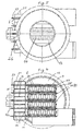
Mit der Bezugsziffer 13 sind in den Fig. 1; 2 und 4 die Rohrböden bezeichnet worden,
die kreisrund sind und im wesentlichen über die Peripherie des Wärmetauschers
1 überstehen, wenn von den überstehenden Bereichen 7 der Wärmetauscherplatten
6 abgesehen wird.With the
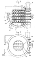
Die Fig. 5 zeigt die Ansicht aus Richtung des Spannringes 26 der Ausführungsform
aus den Fig. 1, 2 und 4. Zu erkennen ist der eine Sammelraum 21 und die
am Randflansch 23 verbundenen Wärmetauscherplatten 6. Außerdem geht der
eine Rohrboden 13 und die dort endenden Strömungskanäle 14 aus dieser Darstellung
hervor.
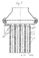
In dem Ausführungsbeispiel nach Fig. 6 wurde gänzlich auf Inneneinsätze 24 in
den Flachrohren 8 verzichtet. Statt dessen wurden die Wandungen der aus zwei
Halbschalen 8/1 und 8/2 bestehenden Flachrohre 8 mit einer deutlichen wellenartigen
Struktur 22 ausgebildet. Die Wellenberge und die Wellentäler verlaufen hier
jedoch, im Unterschied zu der wellenförmigen Struktur 22 des vorher und am
Ende beschriebenen Ausführungsbeispieles (an den Wärmetauscherplatten 6), in
Längsrichtung der Flachrohre 8 bzw. der Strömungskanäle 14. Bei dieser Ausführungsform
sind die Wärmetauscherplatten 6 vorzugsweise mit einer glatten
Oberfläche ausgebildet, abgesehen von den eingeprägten Noppen 11. Diese
Ausführungsform ist für Abgaswärmetauscher besonders geeignet, weil die Gefahr
der Verstopfung der Flachrohre 8 durch Ablagerungen wesentlich geringer
ist.
Fig. 7 zeigt die zum Ausführungsbeispiel in Fig. 6 gehörende Ansicht aus Richtung
des Spannringes 26. Die längsverlaufende wellenartige Struktur 22 der
Strömungskanäle 14 geht auch aus dieser Darstellung hervor.
Der ebenfalls zu dieser Ausführungsform gehörende Längsschnitt in Fig. 8 zeigt,
daß die wellenförmige Struktur 22 vor dem Rohrboden 13 endet. Die Durchzüge
25 am Rohrboden 13 wurden zum Wärmetauscher hin ausgeführt und die
Flachrohre 8 sind mit ihren Enden auf diese Durchzüge 25 aufgesteckt worden 5 shows the view from the direction of the clamping
In the exemplary embodiment according to FIG. 6,
FIG. 7 shows the view belonging to the exemplary embodiment in FIG. 6 from the direction of the clamping
The longitudinal section in FIG. 8 also belonging to this embodiment shows that the undulating
Es muß ferner darauf hingewiesen werden, daß die Fig. 8 einen anderen Anschluß
an die nicht gezeichnete Abgasleitung zeigt.
Die Fig. 9 kann als Querschnitt in Fig. 3 interpretiert werden. Sie unterscheidet
sich von der Fig. 4 dadurch, daß hier geschweißte oder gezogene Flachrohre 8
verwendet worden sind. Ferner wurde die Befestigung mit Hilfe eines Anschlußflansches
27 gewählt, wie es auch in Fig. 3 dargestellt ist.
Die Fig. 10 unterscheidet sich von dem Ausführungsbeispiel in Fig. 9 dadurch,
daß in Fig. 10 die Durchzüge 25 an dem Rohrboden 13 zur Abgasleitung hin
gerichtet sind, während in Fig. 9 die Durchzüge 25 zum Wärmetauscher zeigen.
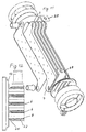
Die Fig. 11 zeigt ein Ausführungsbeispiel, bei dem sich die überkragenden
Bereiche 7, in denen der Sammel-und der Verteilerraum 20, 21 angeordnet sind,
auf gegenüberliegenden Seiten des Wärmetauschers befinden. Deshalb müssen
hier zwei verschiedene Arten von Wärmetauscherplatten 6 verwendet werden.
Als Halterungen 28 sind abgewinkelte Arme aus Stahlblech vorgesehen, die an
den Rohrböden 13 angelötet worden sind.
Fig. 12 zeigt einen Teillängsschnitt, ähnlich Fig. 8, bei dem jedoch die Wärmetauscherplatten
6 eine gewellte Oberflächenstruktur 22 aufweisen, um dadurch
eine höhere Sicherheit gegen Vermischen von Abgas und Kühlwasser zu erreichen.
Im Unterschied zur Fig. 8 sind hier außerdem die Flachrohre 8 in den
Durchzügen 25 des Rohrbodens 13 eingesetzt worden.It must also be pointed out that Fig. 8 shows another connection to the exhaust pipe, not shown.
FIG. 9 can be interpreted as a cross section in FIG. 3. It differs from FIG. 4 in that welded or drawn
10 differs from the exemplary embodiment in FIG. 9 in that in FIG. 10 the
FIG. 11 shows an exemplary embodiment in which the overhanging
Angled arms made of sheet steel are provided as
Fig. 12 shows a partial longitudinal section, similar to Fig. 8, but in which the
Claims (8)
- Exhaust-gas heat exchanger (1) with pairs of tray-shaped heat-exchanger plates (6), each pair of tray-shaped heat-exchanger plates (6) forming a flow duct (9) for cooling water, in that they are assembled and connected mirror-symmetrically at the peripheral rim flange in such a way that the rim flange of one heat-exchanger plate (6) is directed to one side and the rim flange of the other heat-exchanger plate (6) is directed to the opposite side, and also with orifices in the heat-exchanger plates, the said orifices lying on a common line, in order to form the collecting duct and distributing duct for the cooling water, and with further flow ducts (14) for the exhaust gas which are arranged between the said flow ducts, characterized in that the liquid-cooled exhaust-gas heat exchanger (1) is designed in the no-housing form of construction, in that the heat-exchanger plates (6) have projecting regions (7) which are located outside the cross section of the flow ducts (14) for the exhaust gas and which form in these regions (7) the distributing space and collecting space for the cooling water, in that the flow ducts (14) for the exhaust gas are flat tubes (8) which extend approximately along a straight path through the heat exchanger and which issue at opposite ends in tube sheets (13), and in that the walls of at least one of the two types of flow ducts (9; 14) have a surface structure (22) such that full-area contact between the flow ducts (9 and 14) is ruled out.
- Exhaust-gas heat exchanger according to Claim 1, characterized in that the flow ducts (9) for the cooling water have an approximately wavy surface structure.
- Exhaust-gas heat exchanger according to Claims 1 and 2, characterized in that the flat tubes (8) for the exhaust gas which form the flow ducts (14) consist preferably of high-grade steel and have wave-like inner inserts (24) and are either drawn or welded flat tubes (8) or are manufactured from two half-shells (8/1; 8/2) and are connected to one another at the rim flange.
- Exhaust-gas heat exchanger according to Claim 1, characterized in that the flat tubes (8) or flow ducts (14) have wave-shaped walls, the wave crests and troughs being arranged in the direction of the longitudinal axis of the flat tubes (8).
- Exhaust-gas heat exchanger according to one of the preceding claims, characterized in that at the rim flange of the half-shells (8/1; 8/2) forming the flat tubes (8) and/or at the rim flange (23) of the tray-shaped heat-exchanger plates (6) are arranged projecting and angled portions (12) which, when the heat-exchanger plates (6) are being assembled, engage one into the other and serve for the correct positioning of two half-shells in relation to one another.
- Exhaust-gas heat exchanger according to one of the preceding claims, characterized in that the tube sheets (13) consist of high-grade steel and are preferably circular parts with a diameter such that the tube sheets (13) project at least partially beyond the adjoining cross-sectional dimension of the heat exchanger.
- Exhaust-gas heat exchanger according to one of the preceding claims, characterized in that the heat-exchanger plates (6) consist preferably of aluminium and possess supporting bosses (11) which, after assembly, are in contact with one another and are connected at the contact points.
- Exhaust-gas heat exchanger according to one of the preceding claims, characterized in that the centre line, running in the direction of the flat tubes (8), of the exhaust-gas heat exchanger (1) and the exhaust-gas conduit lie on an approximately straight or slightly curved line at least in the vicinity of the inlet and outlet.
Applications Claiming Priority (2)
| Application Number | Priority Date | Filing Date | Title |
|---|---|---|---|
| DE19836889 | 1998-08-14 | ||
| DE19836889A DE19836889A1 (en) | 1998-08-14 | 1998-08-14 | Exhaust gas heat exchanger |
Publications (3)
| Publication Number | Publication Date |
|---|---|
| EP0981035A2 EP0981035A2 (en) | 2000-02-23 |
| EP0981035A3 EP0981035A3 (en) | 2000-06-07 |
| EP0981035B1 true EP0981035B1 (en) | 2003-06-11 |
Family
ID=7877538
Family Applications (1)
| Application Number | Title | Priority Date | Filing Date |
|---|---|---|---|
| EP99115443A Expired - Lifetime EP0981035B1 (en) | 1998-08-14 | 1999-08-05 | Heat exchanger for exhaust gases |
Country Status (4)
| Country | Link |
|---|---|
| EP (1) | EP0981035B1 (en) |
| AT (1) | ATE242860T1 (en) |
| DE (2) | DE19836889A1 (en) |
| ES (1) | ES2201604T3 (en) |
Cited By (1)
| Publication number | Priority date | Publication date | Assignee | Title |
|---|---|---|---|---|
| CN102597680A (en) * | 2009-08-31 | 2012-07-18 | 法雷奥热系统公司 | Heat exchanger |
Families Citing this family (19)
| Publication number | Priority date | Publication date | Assignee | Title |
|---|---|---|---|---|
| DE19846518B4 (en) * | 1998-10-09 | 2007-09-20 | Modine Manufacturing Co., Racine | Heat exchangers, in particular for gases and liquids |
| DE10147555B4 (en) | 2001-09-26 | 2014-01-30 | Behr Gmbh & Co. Kg | Device for fastening an exhaust gas heat exchanger |
| DE10214467A1 (en) * | 2002-03-30 | 2003-10-09 | Modine Mfg Co | Exhaust gas heat exchanger for motor vehicles |
| US6892803B2 (en) | 2002-11-19 | 2005-05-17 | Modine Manufacturing Company | High pressure heat exchanger |
| JP4166591B2 (en) * | 2003-02-13 | 2008-10-15 | カルソニックカンセイ株式会社 | Heat exchanger |
| FR2855602A1 (en) * | 2003-05-27 | 2004-12-03 | Valeo Thermique Moteur Sa | PLATE HEAT EXCHANGER, IN PARTICULAR COOLER FOR RECIRCULATED EXHAUST GASES |
| US7108054B2 (en) | 2003-09-11 | 2006-09-19 | Honeywell International, Inc. | Heat exchanger |
| DE10359806A1 (en) | 2003-12-19 | 2005-07-14 | Modine Manufacturing Co., Racine | Heat exchanger with flat tubes and flat heat exchanger tube |
| DE102004036020A1 (en) * | 2004-07-23 | 2006-02-16 | Behr Gmbh & Co. Kg | Heat exchanger, in particular condenser |
| DE102005053924B4 (en) | 2005-11-11 | 2016-03-31 | Modine Manufacturing Co. | Intercooler in plate construction |
| ATE472708T1 (en) * | 2006-02-17 | 2010-07-15 | Schilling Heinz Kg | DEVICE AND METHOD FOR THERMAL POWER GENERATION |
| JP2008038723A (en) | 2006-08-04 | 2008-02-21 | Toyota Motor Corp | Supporting structure for exhaust system heat exchanger |
| FR2906017B1 (en) | 2006-09-19 | 2012-12-21 | Valeo Systemes Thermiques | HEAT EXCHANGER, PARTICULARLY EXHAUST AIR COOLER. |
| US8424592B2 (en) | 2007-01-23 | 2013-04-23 | Modine Manufacturing Company | Heat exchanger having convoluted fin end and method of assembling the same |
| US20090250201A1 (en) | 2008-04-02 | 2009-10-08 | Grippe Frank M | Heat exchanger having a contoured insert and method of assembling the same |
| GB2461854A (en) * | 2008-07-11 | 2010-01-20 | Stephen John Heard | Heat exchange unit for cooling engine exhaust emissions |
| DE102009010039B4 (en) | 2009-02-21 | 2012-09-20 | Modine Manufacturing Co. | heat exchangers |
| WO2014052309A1 (en) | 2012-09-25 | 2014-04-03 | Modine Manufacturing Company | Heat exchanger |
| CN113244698B (en) * | 2021-05-12 | 2023-03-24 | 天能电池集团(安徽)有限公司 | A surplus sour collection device for leather cap machine negative pressure blast pipe |
Family Cites Families (9)
| Publication number | Priority date | Publication date | Assignee | Title |
|---|---|---|---|---|
| US3537513A (en) * | 1968-03-11 | 1970-11-03 | Garrett Corp | Three-fluid heat exchanger |
| US4310960A (en) * | 1973-04-16 | 1982-01-19 | The Garrett Corporation | Method of fabrication of a formed plate, counterflow fluid heat exchanger and apparatus thereof |
| JPS6186590A (en) * | 1984-10-03 | 1986-05-02 | Hisaka Works Ltd | Heat exchanger |
| US4681155A (en) * | 1986-05-01 | 1987-07-21 | The Garrett Corporation | Lightweight, compact heat exchanger |
| GB2211283B (en) * | 1987-10-20 | 1992-04-15 | Rolls Royce Plc | Heat exchanger |
| JP3359946B2 (en) * | 1993-03-04 | 2002-12-24 | 東京ラヂエーター製造株式会社 | Stacked heat exchanger |
| DE4403144C3 (en) * | 1994-02-02 | 2002-05-29 | Laengerer & Reich Gmbh & Co | Plate heat exchangers |
| DE9406197U1 (en) * | 1994-04-14 | 1994-06-16 | Behr Gmbh & Co | Heat exchanger for cooling exhaust gas from a motor vehicle engine |
| DE29616354U1 (en) * | 1996-09-19 | 1997-01-09 | Laengerer & Reich Gmbh & Co | Exhaust gas heat exchanger |
-
1998
- 1998-08-14 DE DE19836889A patent/DE19836889A1/en not_active Withdrawn
-
1999
- 1999-08-05 EP EP99115443A patent/EP0981035B1/en not_active Expired - Lifetime
- 1999-08-05 ES ES99115443T patent/ES2201604T3/en not_active Expired - Lifetime
- 1999-08-05 DE DE59905912T patent/DE59905912D1/en not_active Expired - Lifetime
- 1999-08-05 AT AT99115443T patent/ATE242860T1/en not_active IP Right Cessation
Cited By (2)
| Publication number | Priority date | Publication date | Assignee | Title |
|---|---|---|---|---|
| CN102597680A (en) * | 2009-08-31 | 2012-07-18 | 法雷奥热系统公司 | Heat exchanger |
| CN102597680B (en) * | 2009-08-31 | 2014-06-11 | 法雷奥热系统公司 | Heat exchanger |
Also Published As
| Publication number | Publication date |
|---|---|
| DE59905912D1 (en) | 2003-07-17 |
| ATE242860T1 (en) | 2003-06-15 |
| ES2201604T3 (en) | 2004-03-16 |
| EP0981035A3 (en) | 2000-06-07 |
| DE19836889A1 (en) | 2000-02-17 |
| EP0981035A2 (en) | 2000-02-23 |
Similar Documents
| Publication | Publication Date | Title |
|---|---|---|
| EP0981035B1 (en) | Heat exchanger for exhaust gases | |
| DE3872162T2 (en) | HONEYCOMB BODY. | |
| DE2946804C2 (en) | ||
| EP1816425B1 (en) | Exhaust gas heat exchanger in an exhaust gas recirculation assembly | |
| EP0772018B1 (en) | Heat exchanger for cooling exhaust gas | |
| EP0881447B1 (en) | Heat exchanger and heat exchanging apparatus for vehicle | |
| DE3423736C2 (en) | ||
| EP0152560B1 (en) | Matrix for a catalytic reactor for purifying exhaust gases | |
| CH655385A5 (en) | HEAT EXCHANGER. | |
| DE2657307A1 (en) | PIPE HEAD FOR A HEAT EXCHANGER | |
| DE2951352C2 (en) | Flat tube heat exchanger | |
| DE4403144C3 (en) | Plate heat exchangers | |
| DE10328846C5 (en) | heat exchangers | |
| DE19709601A1 (en) | Plate heat convector for especially oil/coolant coolers | |
| EP0990868B1 (en) | Heat exchanger | |
| EP2710318A1 (en) | Multiplate heat exchanger | |
| DE3834822A1 (en) | Heat exchanger | |
| EP1788320B1 (en) | Heat exchanger | |
| DE2536657B2 (en) | Heat exchangers for preheating combustion air, in particular for oil-heated industrial furnaces | |
| DE69903895T2 (en) | heat exchangers | |
| DE3148941C2 (en) | Water-cooled oil cooler for internal combustion engines | |
| EP3730890A1 (en) | Plate heat exchanger | |
| DE10236665B4 (en) | Gas-liquid heat exchanger and boiler equipped therewith | |
| EP0177904B1 (en) | Device for exchange of heat between two gases conducted in cross-flow to each other | |
| DE931595C (en) | Countercurrent heat exchanger |
Legal Events
| Date | Code | Title | Description |
|---|---|---|---|
| PUAI | Public reference made under article 153(3) epc to a published international application that has entered the european phase |
Free format text: ORIGINAL CODE: 0009012 |
|
| AK | Designated contracting states |
Kind code of ref document: A2 Designated state(s): AT BE CH CY DE DK ES FI FR GB GR IE IT LI LU MC NL PT SE |
|
| AX | Request for extension of the european patent |
Free format text: AL;LT;LV;MK;RO;SI |
|
| PUAL | Search report despatched |
Free format text: ORIGINAL CODE: 0009013 |
|
| AK | Designated contracting states |
Kind code of ref document: A3 Designated state(s): AT BE CH CY DE DK ES FI FR GB GR IE IT LI LU MC NL PT SE |
|
| AX | Request for extension of the european patent |
Free format text: AL;LT;LV;MK;RO;SI |
|
| 17P | Request for examination filed |
Effective date: 20000516 |
|
| AKX | Designation fees paid |
Free format text: AT BE CH CY DE DK ES FI FR GB GR IE IT LI LU MC NL PT SE |
|
| 17Q | First examination report despatched |
Effective date: 20020425 |
|
| GRAH | Despatch of communication of intention to grant a patent |
Free format text: ORIGINAL CODE: EPIDOS IGRA |
|
| GRAH | Despatch of communication of intention to grant a patent |
Free format text: ORIGINAL CODE: EPIDOS IGRA |
|
| GRAA | (expected) grant |
Free format text: ORIGINAL CODE: 0009210 |
|
| AK | Designated contracting states |
Designated state(s): AT BE CH CY DE DK ES FI FR GB GR IE IT LI LU MC NL PT SE |
|
| PG25 | Lapsed in a contracting state [announced via postgrant information from national office to epo] |
Ref country code: IE Free format text: LAPSE BECAUSE OF FAILURE TO SUBMIT A TRANSLATION OF THE DESCRIPTION OR TO PAY THE FEE WITHIN THE PRESCRIBED TIME-LIMIT Effective date: 20030611 Ref country code: FI Free format text: LAPSE BECAUSE OF FAILURE TO SUBMIT A TRANSLATION OF THE DESCRIPTION OR TO PAY THE FEE WITHIN THE PRESCRIBED TIME-LIMIT Effective date: 20030611 |
|
| REG | Reference to a national code |
Ref country code: GB Ref legal event code: FG4D Free format text: NOT ENGLISH |
|
| REG | Reference to a national code |
Ref country code: CH Ref legal event code: EP |
|
| REG | Reference to a national code |
Ref country code: IE Ref legal event code: FG4D Free format text: GERMAN |
|
| REF | Corresponds to: |
Ref document number: 59905912 Country of ref document: DE Date of ref document: 20030717 Kind code of ref document: P |
|
| PG25 | Lapsed in a contracting state [announced via postgrant information from national office to epo] |
Ref country code: LU Free format text: LAPSE BECAUSE OF NON-PAYMENT OF DUE FEES Effective date: 20030805 Ref country code: CY Free format text: LAPSE BECAUSE OF FAILURE TO SUBMIT A TRANSLATION OF THE DESCRIPTION OR TO PAY THE FEE WITHIN THE PRESCRIBED TIME-LIMIT Effective date: 20030805 Ref country code: AT Free format text: LAPSE BECAUSE OF NON-PAYMENT OF DUE FEES Effective date: 20030805 |
|
| PG25 | Lapsed in a contracting state [announced via postgrant information from national office to epo] |
Ref country code: MC Free format text: LAPSE BECAUSE OF NON-PAYMENT OF DUE FEES Effective date: 20030831 Ref country code: LI Free format text: LAPSE BECAUSE OF NON-PAYMENT OF DUE FEES Effective date: 20030831 Ref country code: CH Free format text: LAPSE BECAUSE OF NON-PAYMENT OF DUE FEES Effective date: 20030831 Ref country code: BE Free format text: LAPSE BECAUSE OF NON-PAYMENT OF DUE FEES Effective date: 20030831 |
|
| PG25 | Lapsed in a contracting state [announced via postgrant information from national office to epo] |
Ref country code: PT Free format text: LAPSE BECAUSE OF FAILURE TO SUBMIT A TRANSLATION OF THE DESCRIPTION OR TO PAY THE FEE WITHIN THE PRESCRIBED TIME-LIMIT Effective date: 20030911 Ref country code: GR Free format text: LAPSE BECAUSE OF FAILURE TO SUBMIT A TRANSLATION OF THE DESCRIPTION OR TO PAY THE FEE WITHIN THE PRESCRIBED TIME-LIMIT Effective date: 20030911 Ref country code: DK Free format text: LAPSE BECAUSE OF FAILURE TO SUBMIT A TRANSLATION OF THE DESCRIPTION OR TO PAY THE FEE WITHIN THE PRESCRIBED TIME-LIMIT Effective date: 20030911 |
|
| REG | Reference to a national code |
Ref country code: SE Ref legal event code: TRGR |
|
| GBT | Gb: translation of ep patent filed (gb section 77(6)(a)/1977) |
Effective date: 20031007 |
|
| REG | Reference to a national code |
Ref country code: IE Ref legal event code: FD4D |
|
| BERE | Be: lapsed |
Owner name: *MODINE MFG CY Effective date: 20030831 |
|
| REG | Reference to a national code |
Ref country code: ES Ref legal event code: FG2A Ref document number: 2201604 Country of ref document: ES Kind code of ref document: T3 |
|
| ET | Fr: translation filed | ||
| REG | Reference to a national code |
Ref country code: CH Ref legal event code: PL |
|
| PLBE | No opposition filed within time limit |
Free format text: ORIGINAL CODE: 0009261 |
|
| STAA | Information on the status of an ep patent application or granted ep patent |
Free format text: STATUS: NO OPPOSITION FILED WITHIN TIME LIMIT |
|
| 26N | No opposition filed |
Effective date: 20040312 |
|
| PGFP | Annual fee paid to national office [announced via postgrant information from national office to epo] |
Ref country code: DE Payment date: 20110907 Year of fee payment: 13 Ref country code: ES Payment date: 20110808 Year of fee payment: 13 Ref country code: FR Payment date: 20110830 Year of fee payment: 13 Ref country code: SE Payment date: 20110827 Year of fee payment: 13 Ref country code: GB Payment date: 20110830 Year of fee payment: 13 |
|
| PGFP | Annual fee paid to national office [announced via postgrant information from national office to epo] |
Ref country code: NL Payment date: 20110824 Year of fee payment: 13 Ref country code: IT Payment date: 20110819 Year of fee payment: 13 |
|
| REG | Reference to a national code |
Ref country code: NL Ref legal event code: V1 Effective date: 20130301 |
|
| REG | Reference to a national code |
Ref country code: SE Ref legal event code: EUG |
|
| GBPC | Gb: european patent ceased through non-payment of renewal fee |
Effective date: 20120805 |
|
| PG25 | Lapsed in a contracting state [announced via postgrant information from national office to epo] |
Ref country code: NL Free format text: LAPSE BECAUSE OF NON-PAYMENT OF DUE FEES Effective date: 20130301 Ref country code: SE Free format text: LAPSE BECAUSE OF NON-PAYMENT OF DUE FEES Effective date: 20120806 |
|
| REG | Reference to a national code |
Ref country code: FR Ref legal event code: ST Effective date: 20130430 |
|
| PG25 | Lapsed in a contracting state [announced via postgrant information from national office to epo] |
Ref country code: IT Free format text: LAPSE BECAUSE OF NON-PAYMENT OF DUE FEES Effective date: 20120805 |
|
| PG25 | Lapsed in a contracting state [announced via postgrant information from national office to epo] |
Ref country code: GB Free format text: LAPSE BECAUSE OF NON-PAYMENT OF DUE FEES Effective date: 20120805 Ref country code: DE Free format text: LAPSE BECAUSE OF NON-PAYMENT OF DUE FEES Effective date: 20130301 |
|
| PG25 | Lapsed in a contracting state [announced via postgrant information from national office to epo] |
Ref country code: FR Free format text: LAPSE BECAUSE OF NON-PAYMENT OF DUE FEES Effective date: 20120831 |
|
| REG | Reference to a national code |
Ref country code: DE Ref legal event code: R119 Ref document number: 59905912 Country of ref document: DE Effective date: 20130301 |
|
| REG | Reference to a national code |
Ref country code: ES Ref legal event code: FD2A Effective date: 20131021 |
|
| PG25 | Lapsed in a contracting state [announced via postgrant information from national office to epo] |
Ref country code: ES Free format text: LAPSE BECAUSE OF NON-PAYMENT OF DUE FEES Effective date: 20120806 |