EP0980968A1 - Dispositif d'admission pour moteur à combustion interne - Google Patents
Dispositif d'admission pour moteur à combustion interne Download PDFInfo
- Publication number
- EP0980968A1 EP0980968A1 EP98115681A EP98115681A EP0980968A1 EP 0980968 A1 EP0980968 A1 EP 0980968A1 EP 98115681 A EP98115681 A EP 98115681A EP 98115681 A EP98115681 A EP 98115681A EP 0980968 A1 EP0980968 A1 EP 0980968A1
- Authority
- EP
- European Patent Office
- Prior art keywords
- resonance
- suction device
- tube
- disks
- housing
- Prior art date
- Legal status (The legal status is an assumption and is not a legal conclusion. Google has not performed a legal analysis and makes no representation as to the accuracy of the status listed.)
- Withdrawn
Links
Images


Classifications
-
- F—MECHANICAL ENGINEERING; LIGHTING; HEATING; WEAPONS; BLASTING
- F02—COMBUSTION ENGINES; HOT-GAS OR COMBUSTION-PRODUCT ENGINE PLANTS
- F02B—INTERNAL-COMBUSTION PISTON ENGINES; COMBUSTION ENGINES IN GENERAL
- F02B27/00—Use of kinetic or wave energy of charge in induction systems, or of combustion residues in exhaust systems, for improving quantity of charge or for increasing removal of combustion residues
- F02B27/02—Use of kinetic or wave energy of charge in induction systems, or of combustion residues in exhaust systems, for improving quantity of charge or for increasing removal of combustion residues the systems having variable, i.e. adjustable, cross-sectional areas, chambers of variable volume, or like variable means
- F02B27/0226—Use of kinetic or wave energy of charge in induction systems, or of combustion residues in exhaust systems, for improving quantity of charge or for increasing removal of combustion residues the systems having variable, i.e. adjustable, cross-sectional areas, chambers of variable volume, or like variable means characterised by the means generating the charging effect
- F02B27/0247—Plenum chambers; Resonance chambers or resonance pipes
- F02B27/0257—Rotatable plenum chambers
-
- F—MECHANICAL ENGINEERING; LIGHTING; HEATING; WEAPONS; BLASTING
- F02—COMBUSTION ENGINES; HOT-GAS OR COMBUSTION-PRODUCT ENGINE PLANTS
- F02B—INTERNAL-COMBUSTION PISTON ENGINES; COMBUSTION ENGINES IN GENERAL
- F02B27/00—Use of kinetic or wave energy of charge in induction systems, or of combustion residues in exhaust systems, for improving quantity of charge or for increasing removal of combustion residues
- F02B27/02—Use of kinetic or wave energy of charge in induction systems, or of combustion residues in exhaust systems, for improving quantity of charge or for increasing removal of combustion residues the systems having variable, i.e. adjustable, cross-sectional areas, chambers of variable volume, or like variable means
- F02B27/0205—Use of kinetic or wave energy of charge in induction systems, or of combustion residues in exhaust systems, for improving quantity of charge or for increasing removal of combustion residues the systems having variable, i.e. adjustable, cross-sectional areas, chambers of variable volume, or like variable means characterised by the charging effect
- F02B27/0215—Oscillating pipe charging, i.e. variable intake pipe length charging
- F02B27/0221—Resonance charging combined with oscillating pipe charging
-
- F—MECHANICAL ENGINEERING; LIGHTING; HEATING; WEAPONS; BLASTING
- F02—COMBUSTION ENGINES; HOT-GAS OR COMBUSTION-PRODUCT ENGINE PLANTS
- F02B—INTERNAL-COMBUSTION PISTON ENGINES; COMBUSTION ENGINES IN GENERAL
- F02B27/00—Use of kinetic or wave energy of charge in induction systems, or of combustion residues in exhaust systems, for improving quantity of charge or for increasing removal of combustion residues
- F02B27/02—Use of kinetic or wave energy of charge in induction systems, or of combustion residues in exhaust systems, for improving quantity of charge or for increasing removal of combustion residues the systems having variable, i.e. adjustable, cross-sectional areas, chambers of variable volume, or like variable means
- F02B27/0226—Use of kinetic or wave energy of charge in induction systems, or of combustion residues in exhaust systems, for improving quantity of charge or for increasing removal of combustion residues the systems having variable, i.e. adjustable, cross-sectional areas, chambers of variable volume, or like variable means characterised by the means generating the charging effect
- F02B27/0247—Plenum chambers; Resonance chambers or resonance pipes
- F02B27/0263—Plenum chambers; Resonance chambers or resonance pipes the plenum chamber and at least one of the intake ducts having a common wall, and the intake ducts wrap partially around the plenum chamber, i.e. snail-type
-
- Y—GENERAL TAGGING OF NEW TECHNOLOGICAL DEVELOPMENTS; GENERAL TAGGING OF CROSS-SECTIONAL TECHNOLOGIES SPANNING OVER SEVERAL SECTIONS OF THE IPC; TECHNICAL SUBJECTS COVERED BY FORMER USPC CROSS-REFERENCE ART COLLECTIONS [XRACs] AND DIGESTS
- Y02—TECHNOLOGIES OR APPLICATIONS FOR MITIGATION OR ADAPTATION AGAINST CLIMATE CHANGE
- Y02T—CLIMATE CHANGE MITIGATION TECHNOLOGIES RELATED TO TRANSPORTATION
- Y02T10/00—Road transport of goods or passengers
- Y02T10/10—Internal combustion engine [ICE] based vehicles
- Y02T10/12—Improving ICE efficiencies
Definitions
- the invention relates to a suction device for a Internal combustion engine according to the preamble of the main claim.
- Such a suction device is, for example, from DE-OS 39 21 081 known.
- This known suction device with an intake manifold system for a multi-cylinder internal combustion engine has a cylindrical intake manifold and leading to the individual cylinders Individual intake pipes on the around the intake manifold led around and in the longitudinal direction of the same side by side are arranged.
- Each tube is available in a vibrating tube length Intake manifold with the intake manifold over two in one Angular distance from each other in the peripheral wall of the intake manifold provided control openings in connection.
- a tubular rotary valve is arranged, the at least one control slot for each individual suction pipe having.
- This control slot is in one End position of the rotary valve with the first control opening connected while the other control opening is covered by the wall of the rotary valve.
- the control slot comes with the second control port in connection, creating a short Length of the vibrating tube is set.
- a switchover is also known in itself between a so-called vibrating tube and resonance tube charging in an intake system.
- the object is achieved in that in a suction device of the type mentioned advantageously a modular intake manifold concept, especially for multi-cylinder internal combustion engines the characteristics of the characterizing part of the main claim becomes.
- the intake manifold concept according to the invention relates to an intake device with a particularly advantageous switchover between resonance and vibrating tube charging the sucked air. It also becomes one stepless swing tube length adjustment and a stepless Adjustment of the length of the resonance pipe enables also a stepped resonance tube cross-section adjustment is feasible and connected with the vibrating tube suction system can be. This gives you the opportunity by an appropriate design of the by Housing formed outer resonance tube wall a resonance tube to be able to lock each resonance collector. All Adjustment interventions can be carried out with embodiments according to the invention advantageously, for example with only one common servomotor; Sub-functions, e.g. Change of the resonance tube cross section can also be used with a separate servomotor be performed.
- the switching can be carried out according to an embodiment bypassed by the lengths of the resonance tube and vibrating tube optimally on each other at any speed be coordinated. It can then be used throughout a resonance charging system at each operating point of the internal combustion engine to be used. The effort for one there is no special resonance flap and the operating behavior of the engine, depending on the design improved.
- the constants KS and KR can be different here, ie with a certain speed increase the tube lengths of the vibrating tube and the resonance tube have to be shortened by different amounts.
- the relationship between the angle of rotation ⁇ and the engine speed n is to be adapted in a motor-specific manner.
- the resonance flap i.e. the panes with windows and if necessary, an iris diaphragm and in principle the resonance circuit is eliminated. Instead, would be closed Walls with a central passage for the shaft complete the resonance collector. The construction of the intake manifold would remain in the suction device according to the invention otherwise unchanged.
- Intake device becomes more advantageous Way of building the housing of the suction device and especially the internal sealing technology improved that the intake manifold can be manufactured more cost-effectively while promoting modularization.
- the suction device is no longer longitudinal, i.e. in the plane of the axis of rotation contained in the intake manifold Adjusting discs, but divided perpendicular to it.
- the surrounding Housing becomes similar to the inner workings, the adjusting washers, made up of individual slices. Otherwise necessary sealing washers are eliminated. Instead are on the adjusting discs, preferably on the outer Part of the adjusting disc, which is made up of two parts, Injection molded sealing lips
- the sealing lips of this embodiment seal between the adjustment discs and those protruding into the intake manifold encircling housing wall that the function of the sealing washers takes over.
- the adjusting disc, or just their Part that carries the sealing lips does not have to come out of the Housing material.
- the material should meet the requirements the sealing lip geometry and the friction to the housing consider.
- the requirements regarding dimensional accuracy and axial runout on the adjusting discs are included this alternative concept less.
- the adjustment disks are still threaded on a shaft. You are no longer tensioned with a spring. At least on the end faces of the housing are end disks to be provided with a shaft bearing.
- the drive of the Wave advantageously takes place in one of the subclaims specified way for stepless Adjustment of the respective pipe lengths.
- two different housing elements and two different Adjusting washers In versions with different Diameter for the respective vibrating tube and at least there is the tuned tube two different housing elements and two different Adjusting washers.
- the modular structure of the intake manifold is thereby significantly simplified. Depending on the number of cylinders the internal combustion engine and the respective intake manifold concept different number of adjustment and housing disks assembled. Depending on the concept, the individual housing or adjusting disks are all in the same orientation mounted (e.g. for in-line engines with only oscillating tube charging) or alternately e.g. Mounted rotated by 180 ° (e.g. when combining resonance and vibrating tube charging).
- the pipe branches out of these housing washers should be completely in the housing disc.
- the corresponding pipe sections do not have to be replaced by a Assembly of two adjacent housing disks are generated, whereby the connection of the housing washers to each
- connection of the housing disks to each other can easily done according to the tongue and groove principle, the groove and the tongue have a circular circumference an unchanged geometry.
- the connection can e.g. by snapping e.g. with a sealing ring, or welding respectively.
- the entire intake manifold can advantageously do this pre-assembled and pre-tensioned, then in one Operation of all housing washers using laser welding to connect with the adjacent panes.
- the suction pipe can simplify the principle and the Execution of those facing the cylinder head, i.e. Swing tube end pieces located downstream of the intake manifold base body be separated.
- the swing tube end pieces and Basic bodies are e.g. connected by means of rubber sleeves.
- an existing one described above Pre-collector, or the pipeline to this, can be comparable Be tied up way. Is not a pre-collector present, the inflow from the throttle valve in the inner collecting space can also be done axially.
- FIG. 1 A suction device shown in Figure 1 for a Internal combustion engine not explained in detail here a housing 1, which consists of individual functional areas is built up, the areas denoted by S. Vibrating tubes and the areas labeled R with resonance tubes represent. To explain these areas is also made to Figure 2 and Figure 3, wherein 2 shows a section through a vibrating tube S. along the section line B-B from Figure 1 and the figure 3 shows a section through a resonance tube R according to FIG Show section line C-C of Figure 1.
- the vibrating tube S according to FIG. 2 is in the exemplary embodiment a plastic part that consists of an upper Housing part 2, a lower housing part 3 and one rotatable adjusting disc 4b inside, the respective housing parts 2 and 3 part of the corresponding Housing parts of the suction device.
- the Shaft 5 is in two bearing caps 6 and 7 with two Steel discs 49 stored and can either with a Electric motor 8 directly or with a belt drive 9 and an electric motor 10 as an actuator.
- the adjusting disks 4a (FIG. 3) and 4b (FIG. 2) can preferably be made of plastic, which may are in several parts and put together to form a disc by e.g. Snap, weld, glue or the like.
- a displacement in the adjusting discs 4a, 4b on the outer circumference is suitable, the volume in the resulting internal resonance volume to a desired maximum volume.
- the Resonance tubes R which are usually two tubes of accordingly larger cross section than the vibrating tubes are in the embodiment of the invention for the 6-cylinder engine in 2x2 pipes from Swing tube diameter. This means that all adjusting washers 4a, 4b with the exception of the two internal ones which, as explained below, also switch discs are exactly the same.
- the entire suction device 1 is thus of shell construction, preferably made of plastic, and consists of the two housing parts 2 and 3, the bearing caps 6 and 7 for shaft 5, with another Area 11 of the housing parts a cover for the belt drive 9 and one described below Cover of a pre-collector for the intake air is available.
- the connection of these housing parts can by means of welding, screwing and / or snapping, gluing, Overmolding, hot riveting, cold riveting or staples etc. done.
- the central shaft 5 can either be carried out continuously or in the plug-on area the central pulley for the belt drive 9 divided.
- the middle Bearing in the area of the belt drive 9 can also through the solid steel washers 49 instead of with thin sealing washers can be achieved.
- This so-called Steel frame gives the housing of the suction device a Stiffness, the steel washers at the same time are the fixed points with regard to the length compensation. Tolerances act starting from the central steel discs outwards in both directions.
- the function of the suction device is first of all based on of Figures 2 and 3 explained.
- the adjusting disks 4a ( Figure 3) and 4b ( Figure 2) are according to the arrow 20 um an angle of about 270 ° rotatable and have a Spokes 21a, 21b arranged circumferential element 22a, 22b that is designed so that there is at least one Opens connection opening 23a, 23b.
- the one in the aspirator air drawn in passes through a Pre-collector 24 according to arrow 25 of Figure 3 in the Resonance tube R.
- the pre-collector 24 can be seen from the top in FIG remove, the air sucked in here Throttle valve, not shown, in the input 26 of the Pre-collector 24 flows.
- the air drawn in continues to flow through the resonance tube R according to Figure 3 according to arrow 25.1 and can through the connection opening 23a centrally into the area the adjusting disc 4a and then through the common Resonance volume according to arrow 25.3 according to FIG. 2 through the connection opening 23b into the axially adjacent one Enter the vibrating tube S and thus reach the inlet on the cylinder head of the internal combustion engine according to Arrow 25.4 at exit 28.
- the drive 9 for the adjustment of the Adjustment pulleys 4a and 4b via the pulley 11 and the electric motor 10 is shown.
- the drive 9 can be carried out in addition that a position detection the pulley 11 or the motor 10 feasible is.
- a device for tensioning the drive belt 30 is via rollers 31 or alternatively according to Figure 5a realized a resilient sliding shoe 32.
- a housing cover 40 of the electric motor 10 carries here at the same time the belt tensioner 31 or 32 and ensures at the same time the fastening of the electric motor 10.
- This cover 40 can be designed to be vibration-damped.
- the device the belt tension must be in the two directions of rotation Take into account, and can therefore be in the form of a bilateral from the outside the belt 30 exciting unit, like explained with roller 31 or slide shoe 32, executed his.
- Belt tensioning device has a positive effect on their function, because the empty span is tensioned more when the Lasttrum bends the belt tensioner away on his side.
- a stepper motor which may have an integrated electronic control is provided or a DC motor with position detection, for example via a potentiometer or an incremental encoder.
- the mounting of these actuators can alternatively to Embodiment shown also axis in axis protruding from the front. It can be modular can be mounted on the left or right with helical gear units, close-fitting with worm gear, on the front plugged in or integrated in the housing cover his.
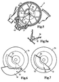
- FIG. 5 shows a section D-D in Figure 1, a device for switching between resonance and vibrating tube charging in the intake device shown, with on the shaft 5 accordingly modified adjusting disc with a rotating window 33 and a fixed sealing switching disc (Steel disc 49) with a window 34 present whose function is explained below.
- the adjusting disks 4a, 4b (here in total 10 Piece) secured against twisting, but slightly tumbling are stored in order to prevent any possible plan impact balance.
- the adjusting disks 4a for the swinging tubes S and 4b for the resonance pipes R lie alternately side by side and rotate in the same direction.
- the Vibrating tubes S have the distance between the cylinders of the connected Internal combustion engine.
- the resonance pipes R lie in the resulting gaps in between. This leads to a very compact design.
- a sealing slide plate 35 fixed in the housing for example from spring steel sheet and an outer molded sealing ring 36.
- the outer, elastic Sealing ring 36 seals against housing 1 the suction device, creating a two-part housing can be used with the inevitable parting line is.
- the inner area of the spring steel washer 35 is Seal and ideal friction partner of the adjusting washers 4a and 4b, the outer region of the spring steel disc 35 through a corrugated membrane-like embossing for a tolerance-compensating decoupling between the Seal outside and the sealing / sliding surface inside ensures.
- the design of the geometry of the windows according to the figure 5 can be used to design the opening characteristics (here the opening cross section between the resonance volumes 42 and 43 above the angle of rotation) can be used. So is it is possible by designing the windows accordingly the connection cross-section ideally the engine operating behavior adapt and then e.g. at very high Switching speeds back to resonance charging, after that with increasing speed at medium speeds switched from resonance charging to vibrating tube charging has been.
- the maximum cross section should be at 6-cylinder engines at least 1.5 to 2.0 times as large be like the cross section of the vibrating tube.
- Alternatives are also solutions based on the principle of a photo lens possible with an iris diaphragm, which is shown in FIG. 6, FIG and Figure 8 are shown.
- the control can be done by means of a cam 53 on the lamella 50 and a guide through the fixed disk Sealing switch plate 54 take place.
- the Leadership can be completely from this sealing switching disc 54 are adopted, there are no return springs or the like is required.
- the sealing switching disc 54 can by special training Steel disc 49, the adjoining adjusting disc or made from a separate aperture component his.
- Figure 6 shows the open and the Figure 7 shows the closed position.
- a number of slats 55 arranged so that they are each about a pivot point 56 can be moved so that there is a variable Iris diaphragm results.
- the guidance of the slats 55 around the fulcrum 56 can, for example, by means of of an internal ring gear 57 (which is only partially here is shown) on corresponding cams on the slats, in a manner comparable to that of FIGS. 6 and 7 explained.
- Figure 9 is shown schematically how the intake air reaches the pre-collector 24 through a throttle valve 41, then by the length and cross section changeable Resonance pipes R in a resonance volume 42 and 43 and then into those connected to the cylinder inlets length-variable vibrating tubes S flows.
- the two resonance volumes 42 and 43 are on the example window 33 and shown in FIG 34 interconnectable or separable. This results in a Switching between resonance and vibrating tube charging in the suction device.
- the sealing of the individual vibrating and resonance pipes R and S with each other and the resonance and vibrating tubes R / S to the resonance collector 42, 43 is in the invention important for the function of the suction pipe.
- the seal 36 (see FIG. 1) on the outer circumference of the sealing washers 35 enables in particular the seal between the Vibrating tubes S and the resonance tubes R at the joint the housing cover 2 and 3.
- the seal between the vibrating tube S or the resonance tube R and the Resonance collector takes place on a friction surface 37 between Spring steel sheet of the sealing washer 35 and the respective Adjusting disc 4a, 4b.
- the left and right half pulley sets the suction device 1 are clamped by means of springs.
- the strength of the spring preload is experimental to investigate. It just has to be so high that the discs lie close together and the Friction still remains small enough for the necessary To keep drive power as low as possible.
- the Spring tension should be in the disc packages with length tolerances do not fluctuate too much (small spring constant).
- the springs 38 and 39 are on the End faces in the bearing caps 6 and 7.
- FIG 10 is a diagram of the changes in the Geometry of the suction device 1 as a function of Angle of rotation of the driven shaft 5 shown.
- the so-called vibrating tube length is the shortest route Pipe cross-sectional center line from the resonance collector to Intake valve of the internal combustion engine behind the outlet 28 of the vibrating tube S according to Figure 2. It is by Twisting the adjusting disks 4b is shortened (advantageously e.g. at high engine speeds) or extended (advantageously e.g. at low engine speeds).
- the totem branching off in short positions Arms, i.e. the pipe sections with no flow can if necessary, to the adjustment disks, not shown here 4b attached tongues are covered.
- the length of the vibrating tube is also adjusted if it is should actually be a resonance charge, because the rotation is coupled.
- the length of the resonance pipe is the shortest path of the pipe cross-section center line of the tube R from the pre-collector 24 to the mouth in the resonance collector after the connection opening 23a according to FIG. 3. It is turned the adjusting disks 4a are shortened (advantageously e.g. at high engine speeds) or extended (advantageously e.g. at low engine speeds).
- the dead branches in short positions Arms can also be adjusted to the adjustment disks if necessary 4a attached tongues are covered.
- the length of the tuner pipe is also adjusted if it is actually to be a swinging tube charge, because the rotation is coupled.
- the resonance pipe cross section is the sum of all pipe cross sections, the pre-collector 24 and a resonance collector, connect as described above.
- 2x2 resonance pipes in front In case of a 6-cylinder internal combustion engine are thus here 2x2 resonance pipes in front.
- One of these can advantageously each locked at low engine speeds to reduce the cross section.
- the easiest way to do this is by means of a corresponding Channel geometry of the resonance tube R in the corresponding Half of housing 2 according to Figure 3.
- the long resonance tube position is on one side the suction device the mouth of a resonance tube to the resonance collector by covering it with the wall the housing half 2 closed at a point 27. It Alternatively, inserts are also conceivable that are in certain Positions of the adjusting disc 4a (in the long Position) flowing through the resonance tube R prevent.
- FIG. 11 shows an alternative a housing 50 of a suction device, which essentially Functions of the previously described embodiments corresponds, but instead of a two-part Housing made of the upper and lower part Disks 51 has a composite housing 50.
- the thus extending housing disks perpendicular to the shaft 5 51 form the resonance tubes R and Swing tubes S and are at a joint 52 each packed tightly together and connected.
- the inside of the pipes R and S are based on 2 and 3 described adjusting disks 4a and 4b arranged, which are also constructed from shells are and are joined together at a joint 53.
- the adjusting disks 4a and 4b according to FIG. 11 have on their circumference each sealing lips 54, which on the respective disk wall when the adjusting disks rotate 4a and 4b can slide and still a seal ensure for the intake flow.
- a pipe branch or a pipe section 55 for the coupling of the resonance tube R to the inflow path or shown to the pre-collector. This piece of pipe can 55 complete with the respective housing washer 51 getting produced.
Landscapes
- Engineering & Computer Science (AREA)
- Chemical & Material Sciences (AREA)
- Combustion & Propulsion (AREA)
- Mechanical Engineering (AREA)
- General Engineering & Computer Science (AREA)
- Characterised By The Charging Evacuation (AREA)
- Nozzles For Electric Vacuum Cleaners (AREA)
- Endoscopes (AREA)
- Reciprocating Pumps (AREA)
- Massaging Devices (AREA)
Priority Applications (7)
| Application Number | Priority Date | Filing Date | Title |
|---|---|---|---|
| EP98115681A EP0980968A1 (fr) | 1998-08-20 | 1998-08-20 | Dispositif d'admission pour moteur à combustion interne |
| PCT/EP1999/006038 WO2000011333A1 (fr) | 1998-08-20 | 1999-08-18 | Tubulure d'admission a cylindre d'ouverture et fermeture |
| EP99941639A EP1036264B1 (fr) | 1998-08-20 | 1999-08-18 | Tubulure d'admission a cylindre d'ouverture et fermeture |
| US09/529,831 US6247438B1 (en) | 1998-08-20 | 1999-08-18 | Intake pipe with shift drum |
| AT99941639T ATE234423T1 (de) | 1998-08-20 | 1999-08-18 | Saugrohr mit schaltwalze |
| JP2000566560A JP2002523666A (ja) | 1998-08-20 | 1999-08-18 | 切り替えロールを有する吸い込み管 |
| DE59904530T DE59904530D1 (de) | 1998-08-20 | 1999-08-18 | Saugrohr mit schaltwalze |
Applications Claiming Priority (1)
| Application Number | Priority Date | Filing Date | Title |
|---|---|---|---|
| EP98115681A EP0980968A1 (fr) | 1998-08-20 | 1998-08-20 | Dispositif d'admission pour moteur à combustion interne |
Publications (1)
| Publication Number | Publication Date |
|---|---|
| EP0980968A1 true EP0980968A1 (fr) | 2000-02-23 |
Family
ID=8232488
Family Applications (2)
| Application Number | Title | Priority Date | Filing Date |
|---|---|---|---|
| EP98115681A Withdrawn EP0980968A1 (fr) | 1998-08-20 | 1998-08-20 | Dispositif d'admission pour moteur à combustion interne |
| EP99941639A Expired - Lifetime EP1036264B1 (fr) | 1998-08-20 | 1999-08-18 | Tubulure d'admission a cylindre d'ouverture et fermeture |
Family Applications After (1)
| Application Number | Title | Priority Date | Filing Date |
|---|---|---|---|
| EP99941639A Expired - Lifetime EP1036264B1 (fr) | 1998-08-20 | 1999-08-18 | Tubulure d'admission a cylindre d'ouverture et fermeture |
Country Status (6)
| Country | Link |
|---|---|
| US (1) | US6247438B1 (fr) |
| EP (2) | EP0980968A1 (fr) |
| JP (1) | JP2002523666A (fr) |
| AT (1) | ATE234423T1 (fr) |
| DE (1) | DE59904530D1 (fr) |
| WO (1) | WO2000011333A1 (fr) |
Cited By (4)
| Publication number | Priority date | Publication date | Assignee | Title |
|---|---|---|---|---|
| DE10014282A1 (de) * | 2000-03-22 | 2001-09-27 | Mann & Hummel Filter | Ansaugvorrichtung mit Schwingrohren und längenverstellbaren Resonanzrohren |
| EP1167716A3 (fr) * | 2000-07-01 | 2002-12-18 | Pierburg GmbH | Système de conduits d'air d'admission pour moteur à combustion |
| EP1283335A3 (fr) * | 2001-08-09 | 2003-11-26 | Pierburg GmbH | Système d'admission d'air pour moteurs à combustion interne |
| DE19756332B4 (de) * | 1997-12-18 | 2006-05-24 | Pierburg Gmbh | Luftansaugkanalsystem für eine Brennkraftmaschine |
Families Citing this family (2)
| Publication number | Priority date | Publication date | Assignee | Title |
|---|---|---|---|---|
| US6382162B2 (en) * | 2000-01-31 | 2002-05-07 | Honda Giken Kogyo Kabushiki Kaisha | Variable intake apparatus for in-line four-cylinder internal combustion engine |
| US6637397B2 (en) * | 2000-09-07 | 2003-10-28 | Borgwarner Inc. | Intake manifold for an engine |
Citations (8)
| Publication number | Priority date | Publication date | Assignee | Title |
|---|---|---|---|---|
| JPS6291622A (ja) * | 1985-10-17 | 1987-04-27 | Nissan Motor Co Ltd | 内燃機関の吸気装置 |
| EP0225620A2 (fr) * | 1985-12-13 | 1987-06-16 | Bayerische Motoren Werke Aktiengesellschaft, Patentabteilung AJ-3 | Dispositif d'admission pour moteur à combustion interne à plusieurs cylindres |
| DE3843690A1 (de) * | 1988-12-23 | 1990-07-05 | Bayerische Motoren Werke Ag | Aus schwingrohrsystem und resonanzsystem kombinierte ansauganlage fuer mehrzylinder-brennkraftmaschinen |
| DE3921081A1 (de) | 1989-06-28 | 1991-01-10 | Audi Ag | Saugrohranlage fuer eine mehrzylinder-brennkraftmaschine |
| DE4231804A1 (de) * | 1991-10-01 | 1993-04-08 | Daimler Benz Ag | Ansaugsystem einer mehrzylindrigen luftverdichtenden einspritzbrennkraftmaschine |
| DE4313465A1 (de) * | 1992-05-02 | 1993-11-04 | Volkswagen Ag | Saugrohranordnung mit schwingrohren |
| DE4437663A1 (de) * | 1994-10-21 | 1996-04-25 | Bayerische Motoren Werke Ag | Sauganlage für eine Brennkraftmaschine der V-Bauart |
| EP0848145A2 (fr) | 1996-12-11 | 1998-06-17 | Bayerische Motoren Werke Aktiengesellschaft, Patentabteilung AJ-3 | Système d'admission pour moteur à combustion du type en V |
Family Cites Families (4)
| Publication number | Priority date | Publication date | Assignee | Title |
|---|---|---|---|---|
| DE3807193A1 (de) * | 1988-03-04 | 1989-06-01 | Bayerische Motoren Werke Ag | Ansaugvorrichtung fuer eine brennkraftmaschine |
| DE3829522A1 (de) * | 1988-08-31 | 1990-03-01 | Bayerische Motoren Werke Ag | Ansaugvorrichtung fuer eine brennkraftmaschine |
| DE29716983U1 (de) * | 1996-09-20 | 1998-04-09 | Schöffler, Helmut, 75242 Neuhausen | Vorrichtung zum Führen der von einem Ottomotor angesaugten Luft |
| DE19756332B4 (de) * | 1997-12-18 | 2006-05-24 | Pierburg Gmbh | Luftansaugkanalsystem für eine Brennkraftmaschine |
-
1998
- 1998-08-20 EP EP98115681A patent/EP0980968A1/fr not_active Withdrawn
-
1999
- 1999-08-18 US US09/529,831 patent/US6247438B1/en not_active Expired - Fee Related
- 1999-08-18 WO PCT/EP1999/006038 patent/WO2000011333A1/fr active IP Right Grant
- 1999-08-18 JP JP2000566560A patent/JP2002523666A/ja active Pending
- 1999-08-18 AT AT99941639T patent/ATE234423T1/de not_active IP Right Cessation
- 1999-08-18 EP EP99941639A patent/EP1036264B1/fr not_active Expired - Lifetime
- 1999-08-18 DE DE59904530T patent/DE59904530D1/de not_active Expired - Fee Related
Patent Citations (8)
| Publication number | Priority date | Publication date | Assignee | Title |
|---|---|---|---|---|
| JPS6291622A (ja) * | 1985-10-17 | 1987-04-27 | Nissan Motor Co Ltd | 内燃機関の吸気装置 |
| EP0225620A2 (fr) * | 1985-12-13 | 1987-06-16 | Bayerische Motoren Werke Aktiengesellschaft, Patentabteilung AJ-3 | Dispositif d'admission pour moteur à combustion interne à plusieurs cylindres |
| DE3843690A1 (de) * | 1988-12-23 | 1990-07-05 | Bayerische Motoren Werke Ag | Aus schwingrohrsystem und resonanzsystem kombinierte ansauganlage fuer mehrzylinder-brennkraftmaschinen |
| DE3921081A1 (de) | 1989-06-28 | 1991-01-10 | Audi Ag | Saugrohranlage fuer eine mehrzylinder-brennkraftmaschine |
| DE4231804A1 (de) * | 1991-10-01 | 1993-04-08 | Daimler Benz Ag | Ansaugsystem einer mehrzylindrigen luftverdichtenden einspritzbrennkraftmaschine |
| DE4313465A1 (de) * | 1992-05-02 | 1993-11-04 | Volkswagen Ag | Saugrohranordnung mit schwingrohren |
| DE4437663A1 (de) * | 1994-10-21 | 1996-04-25 | Bayerische Motoren Werke Ag | Sauganlage für eine Brennkraftmaschine der V-Bauart |
| EP0848145A2 (fr) | 1996-12-11 | 1998-06-17 | Bayerische Motoren Werke Aktiengesellschaft, Patentabteilung AJ-3 | Système d'admission pour moteur à combustion du type en V |
Non-Patent Citations (2)
| Title |
|---|
| BAUDER A ET AL: "DIE TRIEBWERKE DES AUDI A8", MTZ MOTORTECHNISCHE ZEITSCHRIFT, vol. 55, no. 5, 1 May 1994 (1994-05-01), pages 256 - 258, 260, 262 - 264, 266/267, XP000439553 * |
| PATENT ABSTRACTS OF JAPAN vol. 011, no. 301 (M - 628) 30 September 1987 (1987-09-30) * |
Cited By (5)
| Publication number | Priority date | Publication date | Assignee | Title |
|---|---|---|---|---|
| DE19756332B4 (de) * | 1997-12-18 | 2006-05-24 | Pierburg Gmbh | Luftansaugkanalsystem für eine Brennkraftmaschine |
| DE10014282A1 (de) * | 2000-03-22 | 2001-09-27 | Mann & Hummel Filter | Ansaugvorrichtung mit Schwingrohren und längenverstellbaren Resonanzrohren |
| US6431136B2 (en) | 2000-03-22 | 2002-08-13 | Filterwerk Mann & Hummel Gmbh | Intake device with ram pipes and longitudinally adjustable resonance pipes |
| EP1167716A3 (fr) * | 2000-07-01 | 2002-12-18 | Pierburg GmbH | Système de conduits d'air d'admission pour moteur à combustion |
| EP1283335A3 (fr) * | 2001-08-09 | 2003-11-26 | Pierburg GmbH | Système d'admission d'air pour moteurs à combustion interne |
Also Published As
| Publication number | Publication date |
|---|---|
| WO2000011333A1 (fr) | 2000-03-02 |
| US6247438B1 (en) | 2001-06-19 |
| DE59904530D1 (de) | 2003-04-17 |
| ATE234423T1 (de) | 2003-03-15 |
| JP2002523666A (ja) | 2002-07-30 |
| EP1036264A1 (fr) | 2000-09-20 |
| EP1036264B1 (fr) | 2003-03-12 |
Similar Documents
| Publication | Publication Date | Title |
|---|---|---|
| EP1105631B1 (fr) | Dispositif d'aspiration pour moteur a combustion interne | |
| DE10212596B4 (de) | Variable Einlassvorrichtung für einen Mehrzylinderverbrennungsmotor | |
| DE19504382A1 (de) | Ansaugsystem | |
| EP0645530A1 (fr) | Moteur à combustion interne avec système d'admission d'air | |
| EP0980968A1 (fr) | Dispositif d'admission pour moteur à combustion interne | |
| EP0902862A1 (fr) | Dispositif de circulation d'air | |
| DE4039992C2 (fr) | ||
| EP1200722B1 (fr) | Dispositif d'etranglement a volet destine au montage dans une jonction a brides | |
| DE10332640B3 (de) | Luftansaugkanalsystem für Verbrennungskraftmaschinen | |
| EP1251253B1 (fr) | Système de soupapes pour fermeture des conduits d'admission d'un système d'admission | |
| WO1996007022A1 (fr) | Dispositif variable d'aspiration d'air | |
| EP0240823B1 (fr) | Compresseur à piston roulant | |
| WO1998035146A1 (fr) | Dispositif d'aspiration pour moteur a combustion interne | |
| EP1030963B1 (fr) | Collecteur d'admission dote d'elements d'insertion | |
| DE19506306A1 (de) | Ansaugvorrichtung für eine Kolbenbrennkraftmaschine | |
| DE10346763A1 (de) | Saugmodul insbesondere für Brennkraftmaschinen | |
| DE10352781B3 (de) | Luftansaugkanalsystem für eine Verbrennungskraftmaschine | |
| EP1764492B2 (fr) | Système d'alimentation d'air frais pour un moteur à combustion interne | |
| DE10247632B4 (de) | Luftansaugkanalsystem | |
| DE202005012790U1 (de) | Ansaugvorrichtung für eine Brennkraftmaschine | |
| DE19747032C1 (de) | Variable Ventilsteuerung für Brennkraftmaschinen | |
| DE19855732A1 (de) | Rohr mit veränderbarem Querschnitt | |
| DE10347574B3 (de) | Luftansaugkanalsystem | |
| WO2004033870A1 (fr) | Dispositif d'admission | |
| DE10103473A1 (de) | Ansaugvorrichtung für eine Brennkraftmaschine |
Legal Events
| Date | Code | Title | Description |
|---|---|---|---|
| PUAI | Public reference made under article 153(3) epc to a published international application that has entered the european phase |
Free format text: ORIGINAL CODE: 0009012 |
|
| AK | Designated contracting states |
Kind code of ref document: A1 Designated state(s): AT BE CH CY DE DK ES FI FR GB GR IE IT LI LU MC NL PT SE |
|
| AX | Request for extension of the european patent |
Free format text: AL;LT;LV;MK;RO;SI |
|
| AKX | Designation fees paid | ||
| STAA | Information on the status of an ep patent application or granted ep patent |
Free format text: STATUS: THE APPLICATION IS DEEMED TO BE WITHDRAWN |
|
| 18D | Application deemed to be withdrawn |
Effective date: 20000824 |
|
| REG | Reference to a national code |
Ref country code: DE Ref legal event code: 8566 |