EP0980968A1 - Intake device for internal combustion engine - Google Patents
Intake device for internal combustion engine Download PDFInfo
- Publication number
- EP0980968A1 EP0980968A1 EP98115681A EP98115681A EP0980968A1 EP 0980968 A1 EP0980968 A1 EP 0980968A1 EP 98115681 A EP98115681 A EP 98115681A EP 98115681 A EP98115681 A EP 98115681A EP 0980968 A1 EP0980968 A1 EP 0980968A1
- Authority
- EP
- European Patent Office
- Prior art keywords
- resonance
- suction device
- tube
- disks
- housing
- Prior art date
- Legal status (The legal status is an assumption and is not a legal conclusion. Google has not performed a legal analysis and makes no representation as to the accuracy of the status listed.)
- Withdrawn
Links
Images


Classifications
-
- F—MECHANICAL ENGINEERING; LIGHTING; HEATING; WEAPONS; BLASTING
- F02—COMBUSTION ENGINES; HOT-GAS OR COMBUSTION-PRODUCT ENGINE PLANTS
- F02B—INTERNAL-COMBUSTION PISTON ENGINES; COMBUSTION ENGINES IN GENERAL
- F02B27/00—Use of kinetic or wave energy of charge in induction systems, or of combustion residues in exhaust systems, for improving quantity of charge or for increasing removal of combustion residues
- F02B27/02—Use of kinetic or wave energy of charge in induction systems, or of combustion residues in exhaust systems, for improving quantity of charge or for increasing removal of combustion residues the systems having variable, i.e. adjustable, cross-sectional areas, chambers of variable volume, or like variable means
- F02B27/0226—Use of kinetic or wave energy of charge in induction systems, or of combustion residues in exhaust systems, for improving quantity of charge or for increasing removal of combustion residues the systems having variable, i.e. adjustable, cross-sectional areas, chambers of variable volume, or like variable means characterised by the means generating the charging effect
- F02B27/0247—Plenum chambers; Resonance chambers or resonance pipes
- F02B27/0257—Rotatable plenum chambers
-
- F—MECHANICAL ENGINEERING; LIGHTING; HEATING; WEAPONS; BLASTING
- F02—COMBUSTION ENGINES; HOT-GAS OR COMBUSTION-PRODUCT ENGINE PLANTS
- F02B—INTERNAL-COMBUSTION PISTON ENGINES; COMBUSTION ENGINES IN GENERAL
- F02B27/00—Use of kinetic or wave energy of charge in induction systems, or of combustion residues in exhaust systems, for improving quantity of charge or for increasing removal of combustion residues
- F02B27/02—Use of kinetic or wave energy of charge in induction systems, or of combustion residues in exhaust systems, for improving quantity of charge or for increasing removal of combustion residues the systems having variable, i.e. adjustable, cross-sectional areas, chambers of variable volume, or like variable means
- F02B27/0205—Use of kinetic or wave energy of charge in induction systems, or of combustion residues in exhaust systems, for improving quantity of charge or for increasing removal of combustion residues the systems having variable, i.e. adjustable, cross-sectional areas, chambers of variable volume, or like variable means characterised by the charging effect
- F02B27/0215—Oscillating pipe charging, i.e. variable intake pipe length charging
- F02B27/0221—Resonance charging combined with oscillating pipe charging
-
- F—MECHANICAL ENGINEERING; LIGHTING; HEATING; WEAPONS; BLASTING
- F02—COMBUSTION ENGINES; HOT-GAS OR COMBUSTION-PRODUCT ENGINE PLANTS
- F02B—INTERNAL-COMBUSTION PISTON ENGINES; COMBUSTION ENGINES IN GENERAL
- F02B27/00—Use of kinetic or wave energy of charge in induction systems, or of combustion residues in exhaust systems, for improving quantity of charge or for increasing removal of combustion residues
- F02B27/02—Use of kinetic or wave energy of charge in induction systems, or of combustion residues in exhaust systems, for improving quantity of charge or for increasing removal of combustion residues the systems having variable, i.e. adjustable, cross-sectional areas, chambers of variable volume, or like variable means
- F02B27/0226—Use of kinetic or wave energy of charge in induction systems, or of combustion residues in exhaust systems, for improving quantity of charge or for increasing removal of combustion residues the systems having variable, i.e. adjustable, cross-sectional areas, chambers of variable volume, or like variable means characterised by the means generating the charging effect
- F02B27/0247—Plenum chambers; Resonance chambers or resonance pipes
- F02B27/0263—Plenum chambers; Resonance chambers or resonance pipes the plenum chamber and at least one of the intake ducts having a common wall, and the intake ducts wrap partially around the plenum chamber, i.e. snail-type
-
- Y—GENERAL TAGGING OF NEW TECHNOLOGICAL DEVELOPMENTS; GENERAL TAGGING OF CROSS-SECTIONAL TECHNOLOGIES SPANNING OVER SEVERAL SECTIONS OF THE IPC; TECHNICAL SUBJECTS COVERED BY FORMER USPC CROSS-REFERENCE ART COLLECTIONS [XRACs] AND DIGESTS
- Y02—TECHNOLOGIES OR APPLICATIONS FOR MITIGATION OR ADAPTATION AGAINST CLIMATE CHANGE
- Y02T—CLIMATE CHANGE MITIGATION TECHNOLOGIES RELATED TO TRANSPORTATION
- Y02T10/00—Road transport of goods or passengers
- Y02T10/10—Internal combustion engine [ICE] based vehicles
- Y02T10/12—Improving ICE efficiencies
Definitions
- the invention relates to a suction device for a Internal combustion engine according to the preamble of the main claim.
- Such a suction device is, for example, from DE-OS 39 21 081 known.
- This known suction device with an intake manifold system for a multi-cylinder internal combustion engine has a cylindrical intake manifold and leading to the individual cylinders Individual intake pipes on the around the intake manifold led around and in the longitudinal direction of the same side by side are arranged.
- Each tube is available in a vibrating tube length Intake manifold with the intake manifold over two in one Angular distance from each other in the peripheral wall of the intake manifold provided control openings in connection.
- a tubular rotary valve is arranged, the at least one control slot for each individual suction pipe having.
- This control slot is in one End position of the rotary valve with the first control opening connected while the other control opening is covered by the wall of the rotary valve.
- the control slot comes with the second control port in connection, creating a short Length of the vibrating tube is set.
- a switchover is also known in itself between a so-called vibrating tube and resonance tube charging in an intake system.
- the object is achieved in that in a suction device of the type mentioned advantageously a modular intake manifold concept, especially for multi-cylinder internal combustion engines the characteristics of the characterizing part of the main claim becomes.
- the intake manifold concept according to the invention relates to an intake device with a particularly advantageous switchover between resonance and vibrating tube charging the sucked air. It also becomes one stepless swing tube length adjustment and a stepless Adjustment of the length of the resonance pipe enables also a stepped resonance tube cross-section adjustment is feasible and connected with the vibrating tube suction system can be. This gives you the opportunity by an appropriate design of the by Housing formed outer resonance tube wall a resonance tube to be able to lock each resonance collector. All Adjustment interventions can be carried out with embodiments according to the invention advantageously, for example with only one common servomotor; Sub-functions, e.g. Change of the resonance tube cross section can also be used with a separate servomotor be performed.
- the switching can be carried out according to an embodiment bypassed by the lengths of the resonance tube and vibrating tube optimally on each other at any speed be coordinated. It can then be used throughout a resonance charging system at each operating point of the internal combustion engine to be used. The effort for one there is no special resonance flap and the operating behavior of the engine, depending on the design improved.
- the constants KS and KR can be different here, ie with a certain speed increase the tube lengths of the vibrating tube and the resonance tube have to be shortened by different amounts.
- the relationship between the angle of rotation ⁇ and the engine speed n is to be adapted in a motor-specific manner.
- the resonance flap i.e. the panes with windows and if necessary, an iris diaphragm and in principle the resonance circuit is eliminated. Instead, would be closed Walls with a central passage for the shaft complete the resonance collector. The construction of the intake manifold would remain in the suction device according to the invention otherwise unchanged.
- Intake device becomes more advantageous Way of building the housing of the suction device and especially the internal sealing technology improved that the intake manifold can be manufactured more cost-effectively while promoting modularization.
- the suction device is no longer longitudinal, i.e. in the plane of the axis of rotation contained in the intake manifold Adjusting discs, but divided perpendicular to it.
- the surrounding Housing becomes similar to the inner workings, the adjusting washers, made up of individual slices. Otherwise necessary sealing washers are eliminated. Instead are on the adjusting discs, preferably on the outer Part of the adjusting disc, which is made up of two parts, Injection molded sealing lips
- the sealing lips of this embodiment seal between the adjustment discs and those protruding into the intake manifold encircling housing wall that the function of the sealing washers takes over.
- the adjusting disc, or just their Part that carries the sealing lips does not have to come out of the Housing material.
- the material should meet the requirements the sealing lip geometry and the friction to the housing consider.
- the requirements regarding dimensional accuracy and axial runout on the adjusting discs are included this alternative concept less.
- the adjustment disks are still threaded on a shaft. You are no longer tensioned with a spring. At least on the end faces of the housing are end disks to be provided with a shaft bearing.
- the drive of the Wave advantageously takes place in one of the subclaims specified way for stepless Adjustment of the respective pipe lengths.
- two different housing elements and two different Adjusting washers In versions with different Diameter for the respective vibrating tube and at least there is the tuned tube two different housing elements and two different Adjusting washers.
- the modular structure of the intake manifold is thereby significantly simplified. Depending on the number of cylinders the internal combustion engine and the respective intake manifold concept different number of adjustment and housing disks assembled. Depending on the concept, the individual housing or adjusting disks are all in the same orientation mounted (e.g. for in-line engines with only oscillating tube charging) or alternately e.g. Mounted rotated by 180 ° (e.g. when combining resonance and vibrating tube charging).
- the pipe branches out of these housing washers should be completely in the housing disc.
- the corresponding pipe sections do not have to be replaced by a Assembly of two adjacent housing disks are generated, whereby the connection of the housing washers to each
- connection of the housing disks to each other can easily done according to the tongue and groove principle, the groove and the tongue have a circular circumference an unchanged geometry.
- the connection can e.g. by snapping e.g. with a sealing ring, or welding respectively.
- the entire intake manifold can advantageously do this pre-assembled and pre-tensioned, then in one Operation of all housing washers using laser welding to connect with the adjacent panes.
- the suction pipe can simplify the principle and the Execution of those facing the cylinder head, i.e. Swing tube end pieces located downstream of the intake manifold base body be separated.
- the swing tube end pieces and Basic bodies are e.g. connected by means of rubber sleeves.
- an existing one described above Pre-collector, or the pipeline to this, can be comparable Be tied up way. Is not a pre-collector present, the inflow from the throttle valve in the inner collecting space can also be done axially.
- FIG. 1 A suction device shown in Figure 1 for a Internal combustion engine not explained in detail here a housing 1, which consists of individual functional areas is built up, the areas denoted by S. Vibrating tubes and the areas labeled R with resonance tubes represent. To explain these areas is also made to Figure 2 and Figure 3, wherein 2 shows a section through a vibrating tube S. along the section line B-B from Figure 1 and the figure 3 shows a section through a resonance tube R according to FIG Show section line C-C of Figure 1.
- the vibrating tube S according to FIG. 2 is in the exemplary embodiment a plastic part that consists of an upper Housing part 2, a lower housing part 3 and one rotatable adjusting disc 4b inside, the respective housing parts 2 and 3 part of the corresponding Housing parts of the suction device.
- the Shaft 5 is in two bearing caps 6 and 7 with two Steel discs 49 stored and can either with a Electric motor 8 directly or with a belt drive 9 and an electric motor 10 as an actuator.
- the adjusting disks 4a (FIG. 3) and 4b (FIG. 2) can preferably be made of plastic, which may are in several parts and put together to form a disc by e.g. Snap, weld, glue or the like.
- a displacement in the adjusting discs 4a, 4b on the outer circumference is suitable, the volume in the resulting internal resonance volume to a desired maximum volume.
- the Resonance tubes R which are usually two tubes of accordingly larger cross section than the vibrating tubes are in the embodiment of the invention for the 6-cylinder engine in 2x2 pipes from Swing tube diameter. This means that all adjusting washers 4a, 4b with the exception of the two internal ones which, as explained below, also switch discs are exactly the same.
- the entire suction device 1 is thus of shell construction, preferably made of plastic, and consists of the two housing parts 2 and 3, the bearing caps 6 and 7 for shaft 5, with another Area 11 of the housing parts a cover for the belt drive 9 and one described below Cover of a pre-collector for the intake air is available.
- the connection of these housing parts can by means of welding, screwing and / or snapping, gluing, Overmolding, hot riveting, cold riveting or staples etc. done.
- the central shaft 5 can either be carried out continuously or in the plug-on area the central pulley for the belt drive 9 divided.
- the middle Bearing in the area of the belt drive 9 can also through the solid steel washers 49 instead of with thin sealing washers can be achieved.
- This so-called Steel frame gives the housing of the suction device a Stiffness, the steel washers at the same time are the fixed points with regard to the length compensation. Tolerances act starting from the central steel discs outwards in both directions.
- the function of the suction device is first of all based on of Figures 2 and 3 explained.
- the adjusting disks 4a ( Figure 3) and 4b ( Figure 2) are according to the arrow 20 um an angle of about 270 ° rotatable and have a Spokes 21a, 21b arranged circumferential element 22a, 22b that is designed so that there is at least one Opens connection opening 23a, 23b.
- the one in the aspirator air drawn in passes through a Pre-collector 24 according to arrow 25 of Figure 3 in the Resonance tube R.
- the pre-collector 24 can be seen from the top in FIG remove, the air sucked in here Throttle valve, not shown, in the input 26 of the Pre-collector 24 flows.
- the air drawn in continues to flow through the resonance tube R according to Figure 3 according to arrow 25.1 and can through the connection opening 23a centrally into the area the adjusting disc 4a and then through the common Resonance volume according to arrow 25.3 according to FIG. 2 through the connection opening 23b into the axially adjacent one Enter the vibrating tube S and thus reach the inlet on the cylinder head of the internal combustion engine according to Arrow 25.4 at exit 28.
- the drive 9 for the adjustment of the Adjustment pulleys 4a and 4b via the pulley 11 and the electric motor 10 is shown.
- the drive 9 can be carried out in addition that a position detection the pulley 11 or the motor 10 feasible is.
- a device for tensioning the drive belt 30 is via rollers 31 or alternatively according to Figure 5a realized a resilient sliding shoe 32.
- a housing cover 40 of the electric motor 10 carries here at the same time the belt tensioner 31 or 32 and ensures at the same time the fastening of the electric motor 10.
- This cover 40 can be designed to be vibration-damped.
- the device the belt tension must be in the two directions of rotation Take into account, and can therefore be in the form of a bilateral from the outside the belt 30 exciting unit, like explained with roller 31 or slide shoe 32, executed his.
- Belt tensioning device has a positive effect on their function, because the empty span is tensioned more when the Lasttrum bends the belt tensioner away on his side.
- a stepper motor which may have an integrated electronic control is provided or a DC motor with position detection, for example via a potentiometer or an incremental encoder.
- the mounting of these actuators can alternatively to Embodiment shown also axis in axis protruding from the front. It can be modular can be mounted on the left or right with helical gear units, close-fitting with worm gear, on the front plugged in or integrated in the housing cover his.
- FIG. 5 shows a section D-D in Figure 1, a device for switching between resonance and vibrating tube charging in the intake device shown, with on the shaft 5 accordingly modified adjusting disc with a rotating window 33 and a fixed sealing switching disc (Steel disc 49) with a window 34 present whose function is explained below.
- the adjusting disks 4a, 4b (here in total 10 Piece) secured against twisting, but slightly tumbling are stored in order to prevent any possible plan impact balance.
- the adjusting disks 4a for the swinging tubes S and 4b for the resonance pipes R lie alternately side by side and rotate in the same direction.
- the Vibrating tubes S have the distance between the cylinders of the connected Internal combustion engine.
- the resonance pipes R lie in the resulting gaps in between. This leads to a very compact design.
- a sealing slide plate 35 fixed in the housing for example from spring steel sheet and an outer molded sealing ring 36.
- the outer, elastic Sealing ring 36 seals against housing 1 the suction device, creating a two-part housing can be used with the inevitable parting line is.
- the inner area of the spring steel washer 35 is Seal and ideal friction partner of the adjusting washers 4a and 4b, the outer region of the spring steel disc 35 through a corrugated membrane-like embossing for a tolerance-compensating decoupling between the Seal outside and the sealing / sliding surface inside ensures.
- the design of the geometry of the windows according to the figure 5 can be used to design the opening characteristics (here the opening cross section between the resonance volumes 42 and 43 above the angle of rotation) can be used. So is it is possible by designing the windows accordingly the connection cross-section ideally the engine operating behavior adapt and then e.g. at very high Switching speeds back to resonance charging, after that with increasing speed at medium speeds switched from resonance charging to vibrating tube charging has been.
- the maximum cross section should be at 6-cylinder engines at least 1.5 to 2.0 times as large be like the cross section of the vibrating tube.
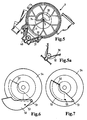
- Alternatives are also solutions based on the principle of a photo lens possible with an iris diaphragm, which is shown in FIG. 6, FIG and Figure 8 are shown.
- the control can be done by means of a cam 53 on the lamella 50 and a guide through the fixed disk Sealing switch plate 54 take place.
- the Leadership can be completely from this sealing switching disc 54 are adopted, there are no return springs or the like is required.
- the sealing switching disc 54 can by special training Steel disc 49, the adjoining adjusting disc or made from a separate aperture component his.
- Figure 6 shows the open and the Figure 7 shows the closed position.
- a number of slats 55 arranged so that they are each about a pivot point 56 can be moved so that there is a variable Iris diaphragm results.
- the guidance of the slats 55 around the fulcrum 56 can, for example, by means of of an internal ring gear 57 (which is only partially here is shown) on corresponding cams on the slats, in a manner comparable to that of FIGS. 6 and 7 explained.
- Figure 9 is shown schematically how the intake air reaches the pre-collector 24 through a throttle valve 41, then by the length and cross section changeable Resonance pipes R in a resonance volume 42 and 43 and then into those connected to the cylinder inlets length-variable vibrating tubes S flows.
- the two resonance volumes 42 and 43 are on the example window 33 and shown in FIG 34 interconnectable or separable. This results in a Switching between resonance and vibrating tube charging in the suction device.
- the sealing of the individual vibrating and resonance pipes R and S with each other and the resonance and vibrating tubes R / S to the resonance collector 42, 43 is in the invention important for the function of the suction pipe.
- the seal 36 (see FIG. 1) on the outer circumference of the sealing washers 35 enables in particular the seal between the Vibrating tubes S and the resonance tubes R at the joint the housing cover 2 and 3.
- the seal between the vibrating tube S or the resonance tube R and the Resonance collector takes place on a friction surface 37 between Spring steel sheet of the sealing washer 35 and the respective Adjusting disc 4a, 4b.
- the left and right half pulley sets the suction device 1 are clamped by means of springs.
- the strength of the spring preload is experimental to investigate. It just has to be so high that the discs lie close together and the Friction still remains small enough for the necessary To keep drive power as low as possible.
- the Spring tension should be in the disc packages with length tolerances do not fluctuate too much (small spring constant).
- the springs 38 and 39 are on the End faces in the bearing caps 6 and 7.
- FIG 10 is a diagram of the changes in the Geometry of the suction device 1 as a function of Angle of rotation of the driven shaft 5 shown.
- the so-called vibrating tube length is the shortest route Pipe cross-sectional center line from the resonance collector to Intake valve of the internal combustion engine behind the outlet 28 of the vibrating tube S according to Figure 2. It is by Twisting the adjusting disks 4b is shortened (advantageously e.g. at high engine speeds) or extended (advantageously e.g. at low engine speeds).
- the totem branching off in short positions Arms, i.e. the pipe sections with no flow can if necessary, to the adjustment disks, not shown here 4b attached tongues are covered.
- the length of the vibrating tube is also adjusted if it is should actually be a resonance charge, because the rotation is coupled.
- the length of the resonance pipe is the shortest path of the pipe cross-section center line of the tube R from the pre-collector 24 to the mouth in the resonance collector after the connection opening 23a according to FIG. 3. It is turned the adjusting disks 4a are shortened (advantageously e.g. at high engine speeds) or extended (advantageously e.g. at low engine speeds).
- the dead branches in short positions Arms can also be adjusted to the adjustment disks if necessary 4a attached tongues are covered.
- the length of the tuner pipe is also adjusted if it is actually to be a swinging tube charge, because the rotation is coupled.
- the resonance pipe cross section is the sum of all pipe cross sections, the pre-collector 24 and a resonance collector, connect as described above.
- 2x2 resonance pipes in front In case of a 6-cylinder internal combustion engine are thus here 2x2 resonance pipes in front.
- One of these can advantageously each locked at low engine speeds to reduce the cross section.
- the easiest way to do this is by means of a corresponding Channel geometry of the resonance tube R in the corresponding Half of housing 2 according to Figure 3.
- the long resonance tube position is on one side the suction device the mouth of a resonance tube to the resonance collector by covering it with the wall the housing half 2 closed at a point 27. It Alternatively, inserts are also conceivable that are in certain Positions of the adjusting disc 4a (in the long Position) flowing through the resonance tube R prevent.
- FIG. 11 shows an alternative a housing 50 of a suction device, which essentially Functions of the previously described embodiments corresponds, but instead of a two-part Housing made of the upper and lower part Disks 51 has a composite housing 50.
- the thus extending housing disks perpendicular to the shaft 5 51 form the resonance tubes R and Swing tubes S and are at a joint 52 each packed tightly together and connected.
- the inside of the pipes R and S are based on 2 and 3 described adjusting disks 4a and 4b arranged, which are also constructed from shells are and are joined together at a joint 53.
- the adjusting disks 4a and 4b according to FIG. 11 have on their circumference each sealing lips 54, which on the respective disk wall when the adjusting disks rotate 4a and 4b can slide and still a seal ensure for the intake flow.
- a pipe branch or a pipe section 55 for the coupling of the resonance tube R to the inflow path or shown to the pre-collector. This piece of pipe can 55 complete with the respective housing washer 51 getting produced.
Abstract
Description
Die Erfindung betrifft eine Ansaugvorrichtung für eine Brennkraftmaschine nach dem Oberbegriff des Hauptanspruchs.The invention relates to a suction device for a Internal combustion engine according to the preamble of the main claim.
Eine solche Ansaugvorrichtung ist beispielsweise aus der DE-OS 39 21 081 bekannt. Diese bekannte Ansaugvorrichtung mit einer Saugrohranlage für eine Mehrzylinder-Brennkraftmaschine weist einen zylindrischen Ansaugverteilerraum und zu den einzelnen Zylindern führende Einzelsaugrohre auf, die um den Ansaugverteilerraum herum geführt und in Längsrichtung desselben nebeneinander angeordnet sind. Zur Erzielung von zwei unterschiedlichen Schwingrohrlängen steht jedes einzelne Saugrohr mit dem Ansaugverteilerraum über zwei in einem Winkelabstand voneinander in der Umfangswand des Ansaugverteilerraums vorgesehene Steueröffnungen in Verbindung.Such a suction device is, for example, from DE-OS 39 21 081 known. This known suction device with an intake manifold system for a multi-cylinder internal combustion engine has a cylindrical intake manifold and leading to the individual cylinders Individual intake pipes on the around the intake manifold led around and in the longitudinal direction of the same side by side are arranged. To achieve two different Each tube is available in a vibrating tube length Intake manifold with the intake manifold over two in one Angular distance from each other in the peripheral wall of the intake manifold provided control openings in connection.
In dem Ansaugverteilerraum dieser bekannten Ansaugvorrichtung ist ein rohrförmiger Drehschieber angeordnet, der für jedes Einzelsaugrohr mindestens einen Steuerschlitz aufweist. Dieser Steuerschlitz steht in einer Endstellung des Drehschiebers mit der ersten Steueröffnung in Verbindung, während die andere Steueröffnung von der Wand des Drehschiebers abgedeckt ist. Dadurch wird eine lange Schwingrohrlänge verwirklicht. Wird der Drehschieber in seine andere Endstellung gedreht, so wird die erste Steueröffnung von der Wand des Drehschiebers abgedeckt, der Steuerschlitz kommt mit der zweiten Steueröffnung in Verbindung, wodurch eine kurze Schwingrohrlänge eingestellt wird.In the intake manifold of this known intake device a tubular rotary valve is arranged, the at least one control slot for each individual suction pipe having. This control slot is in one End position of the rotary valve with the first control opening connected while the other control opening is covered by the wall of the rotary valve. Thereby a long length of vibrating tube is realized. Will the Rotary valve turned to its other end position, see above becomes the first control opening from the wall of the rotary valve covered, the control slot comes with the second control port in connection, creating a short Length of the vibrating tube is set.
Ein Nachteil dieser bekannten Einrichtung ist darin zu sehen, daß keine stufenlose Einstellmöglichkeit für die Schwingrohrlänge gegeben ist. Dies bedeutet, daß ein Optimum an Leistungsausbeute nur in zwei eng begrenzten Drehzahlbereichen der Brennkraftmaschine möglich ist. Die bekannten Einrichtungen betreffen dabei immer nur längenveränderliche Schwingrohrsauganlagen.A disadvantage of this known device is there too see that no stepless adjustment for the Length of the vibrating tube is given. This means that a Optimal power output only in two narrowly limited Speed ranges of the internal combustion engine is possible. The known facilities only ever affect variable length vibrating tube suction systems.
Es ist weiterhin aus der EP 0 848 145 A2 bekannt, eine stufenlose Veränderung der Schwingrohrlänge bei der Ansauganlage für einen V-Verbrennungsmotor vorzunehmen. Bei dieser Anordnung ist eine Trommel als Drehschieber vorhanden, in die die angesaugte Luft axial eintritt und durch die die Luft in das tangential anliegende Ansaugrohr führbar ist. Durch Drehen der Trommel ist hier die veränderbare Länge des für die Luft wirksamen Ansaugrohres auf einfache Weise einstellbar.It is also known from EP 0 848 145 A2, a stepless change in the length of the vibrating tube in the intake system for a V-type internal combustion engine. In this arrangement, a drum is used as a rotary valve available, into which the sucked air enters axially and through which the air enters the tangential intake pipe is feasible. By turning the drum is here the variable length of the air intake pipe easily adjustable.
Für sich gesehen ist ebenfalls bekannt, eine Umschaltung zwischen einer sogenannten Schwingrohr- und Resonanzrohraufladung in einer Ansauganlage vorzunehmen. A switchover is also known in itself between a so-called vibrating tube and resonance tube charging in an intake system.
Es ist somit Aufgabe der Erfindung, eine Ansaugvorrichtung zu schaffen, die eine stufenlose Veränderung der Saugrohrgeometrie erlaubt und einfach in modularer Bauweise herstellbar ist.It is therefore an object of the invention to provide a suction device to create a stepless change in the Manifold geometry allowed and simple in a modular design can be produced.
Erfindungsgemäß wird die Aufgabe dadurch gelöst, dass bei einer Ansaugvorrichtung der eingangs genannten Art in vorteilhafter Weise ein modulares Saugrohrkonzept, insbesondere für Mehrzylinder-Brennkraftmaschinen mit den Merkmalen des Kennzeichens des Hauptanspruchs realisiert wird.According to the invention the object is achieved in that in a suction device of the type mentioned advantageously a modular intake manifold concept, especially for multi-cylinder internal combustion engines the characteristics of the characterizing part of the main claim becomes.
Das erfindungsgemäße Saugrohrkonzept betrifft eine Ansaugvorrichtung mit einer besonders vorteilhaften Umschaltung zwischen Resonanz- und Schwingrohraufladung der angesaugten Luft. Es wird hierbei ebenfalls eine stufenlose Schwingrohrlängenverstellung und eine stufenlose Resonanzrohrlängenverstellung ermöglicht, wobei auch eine stufige Resonanzrohrquerschnittverstellung durchführbar ist und mit der Schwingrohrsauganlage mitgeschaltet werden kann. Hierdurch besteht die Möglichkeit, durch eine entsprechende Gestaltung der durch das Gehäuse gebildeten äußeren Resonanzrohrwand ein Resonanzrohr je Resonanzsammler verschließen zu können. Alle Verstelleingriffe können mit erfindungsgemäßen Ausführungsformen in vorteilhafter Weise, beispielsweise mit nur einem gemeinsamen Stellmotor, erfolgen; Teilfunktionen, z.B. Resonanzrohrquerschnittsveränderung können dabei aber auch mit einem separatem Stellmotor durchgeführt werden. The intake manifold concept according to the invention relates to an intake device with a particularly advantageous switchover between resonance and vibrating tube charging the sucked air. It also becomes one stepless swing tube length adjustment and a stepless Adjustment of the length of the resonance pipe enables also a stepped resonance tube cross-section adjustment is feasible and connected with the vibrating tube suction system can be. This gives you the opportunity by an appropriate design of the by Housing formed outer resonance tube wall a resonance tube to be able to lock each resonance collector. All Adjustment interventions can be carried out with embodiments according to the invention advantageously, for example with only one common servomotor; Sub-functions, e.g. Change of the resonance tube cross section can also be used with a separate servomotor be performed.
Als wesentliche Vorteile des erfindungsgemäßen Saugrohrkonzeptes sind vor allem der modulare Aufbau anzuführen, der das Prinzip der Ansaugvorrichtung auch für z.B. 3- ,4- oder allg. Mehrzylinder-Motoren geeignet macht. Weiterhin sind auf einfache Weise Veränderungen des Resonanz- oder Schwingrohrquerschnitts (z.B. für Motoren einer Familie mit gleichem Zylinderabstand) durch den erfindungsgemäßen Einsatz von Verstellscheiben mit kleinerem oder größerem Außendurchmesser durchzuführen.As essential advantages of the intake manifold concept according to the invention above all the modular structure should be mentioned, the principle of the suction device for e.g. Suitable for 3, 4 or general multi-cylinder engines makes. Furthermore, changes are simple of the resonance or vibrating tube cross-section (e.g. for Engines of a family with the same cylinder spacing) through the use of adjusting disks according to the invention with a smaller or larger outer diameter.
Bei weiteren Ausführungsform der erfindungsgemäßen Ansaugvorrichtung mit stufenlos verstellbaren Rohrlängen kann die erwähnte Umschaltung von Resonanzaufladung zu Schwingaufladung auch mit einer anderen Resonanzschaltung durchgeführt werden.In another embodiment of the suction device according to the invention with infinitely adjustable tube lengths can the mentioned switching from resonance charging to Vibrating charging also with another resonance circuit be performed.
Bei den zuvor beschriebenen Resonanzaufladesysteme ist der Luftaufwand der Brennkraftmaschine in einem gewissen Drehzahlbereich in vorteilhafter Weise verbessert. Die Ursache für das bessere Betriebsverhalten mit Schwingrohraufladung bei diesen Motordrehzahlen liegt darin, daß das Resonanzsystem und das Schwingrohrsystem nur in einem bestimmten Bereich gut aufeinander abgestimmt sind. Bei anderen Drehzahlen bewirkt das dort schlecht abgestimmte Gesamtsystem aus Resonanz- und Schwingrohren eine Verschlechterung des Betriebsverhaltens, so dass dort, wie beschrieben, auf eine Schwingrohraufladung umgeschaltet wird.In the previously described resonance charging systems the air expenditure of the internal combustion engine in a certain Speed range improved in an advantageous manner. The cause of the better operating behavior with Vibrating tube charging is at these engine speeds in that the resonance system and the vibrating tube system only well coordinated in a certain area are. At other speeds, it does that there poorly tuned overall system of resonance and Vibrating tubes a deterioration in operational behavior, so that, as described, on a vibrating tube charge is switched.
Die Umschaltung kann gemäß eines Ausführungsbeispiels dadurch umgangen werden, dass die Längen von Resonanzrohr und Schwingrohr bei jeder Drehzahl optimal aufeinander abgestimmt werden. Es kann dann durchgängig in jedem Betriebspunkt der Brennkraftmaschine ein Resonanzaufladesystem benutzt werden. Der Aufwand für eine besondere Resonanzklappe entfällt hier und das Betriebsverhalten des Motors wird je nach Auslegung sogar verbessert.The switching can be carried out according to an embodiment bypassed by the lengths of the resonance tube and vibrating tube optimally on each other at any speed be coordinated. It can then be used throughout a resonance charging system at each operating point of the internal combustion engine to be used. The effort for one there is no special resonance flap and the operating behavior of the engine, depending on the design improved.
Bezüglich der Schwingrohre ist bei niedrigen Drehzahlen eher eine lange, bei hohen Motordrehzahlen eher eine kurze Schwingrohrlänge von Vorteil. Bei den Resonanzrohren verhält sich dieser Zusammenhang ähnlich. Unterschiedlich bei den beiden Rohren ist das Niveau der Rohrlänge und die bei Drehzahlerhöhung unterschiedlich starke Abnahme der Rohrlänge.Regarding the vibrating tubes is at low speeds rather a long one, at high engine speeds rather one short swing tube length is an advantage. With the resonance pipes this relationship behaves similarly. Differently the level of the two pipes is Pipe length and different when increasing speed sharp decrease in pipe length.
Werden mit n die Drehzahl der Brennkraftmaschine und
mit LS und LR die Langen von Schwingrohr (LS) und Resonanzrohr
(LR) bezeichnet, so gilt für die optimalen
Rohrlängen:
Die Realisierung einer solchen Resonanzaufladung ist mit einer entsprechenden Abwandlung der zuvor beschriebenen Ausführungsbeispiele auf einfache Weise möglich. Sind die Rohrlängen von Schwingrohr und Resonanzrohr quasi auf einer Scheibe aufgewickelt, so lassen sich Unterschiede in den Konstanten KS und KR einfach durch verschiedene Durchmesser der Verstellscheiben realisieren.The realization of such a resonance charge is with a corresponding modification of the previously described Embodiments possible in a simple manner. Are the tube lengths of the vibrating tube and the resonance tube quasi wound on a disc, so you can Differences in the constants KS and KR simply through realize different diameters of the adjustment disks.
Für den Fall, dass KR kleiner ist als KS, d.h. die Resonanzrohrlänge sich nicht so stark ändert wie die Schwingrohrlänge, läge der Unterschied darin, dass die Verstellscheiben der Resonanzrohre kleiner im Durchmesser wären und das Gehäuse für diese Rohre entsprechend eingezogen wäre, um den Rohrquerschnitt beizubehalten. Für den Fall, daß KS kleiner ist als KR, verhielte sich der Sachverhalt umgekehrt, d.h. die Scheiben der Schwingrohre wären kleiner. Beim Aufbau des Saugrohres nach einem der eingangs beschriebenen Ausführungsbeispiele ist darauf zu achten, dass die axialen Reibflächen an den Verstellscheiben von Schwingrohr und Resonanzrohr auf einem gleichem Radius liegen, auch wenn sich die Außendurchmesser der Verstellscheiben unterscheiden.In the event that KR is smaller than KS, i.e. the resonance tube length doesn't change as much as that Swing tube length, the difference would be that the Adjustment discs of the resonance pipes smaller in diameter would be and the housing for these pipes accordingly would be moved in to maintain the pipe cross-section. In the event that KS is smaller than KR, this would be the case the situation is reversed, i.e. the discs of the Swing tubes would be smaller. When building the suction pipe according to one of the embodiments described above care must be taken that the axial friction surfaces on the adjusting discs of the vibrating tube and the resonance tube lie on the same radius, even if the outer diameters of the adjustment disks differ.
Bei dem zuletzt beschriebenen Ausführungsbeispiel kann die Resonanzklappe, d.h. die Scheiben mit Fenstern und gegebenenfalls einer Irisblende und damit im Prinzip die Resonanzschaltung entfallen. Stattdessen würden geschlossene Wände mit mittigem Durchtritt für die Welle den Resonanzsammler abschließen. Der Aufbau des Saugrohres in der erfindungsgemäßen Ansaugvorrichtung bliebe ansonsten unverändert.In the last described embodiment, can the resonance flap, i.e. the panes with windows and if necessary, an iris diaphragm and in principle the resonance circuit is eliminated. Instead, would be closed Walls with a central passage for the shaft complete the resonance collector. The construction of the intake manifold would remain in the suction device according to the invention otherwise unchanged.
Bei einer weiteren vorteilhaften Ausführungsform der erfindungsgemäßen Ansaugvorrichtung wird in vorteilhafter Weise der Aufbau des Gehäuses der Ansaugvorrichtung und insbesondere die interne Abdichttechnik so verbessert, dass das Saugrohr kostengünstiger hergestellt werden kann und dabei auch die Modularisierung gefördert ist.In a further advantageous embodiment of the invention Intake device becomes more advantageous Way of building the housing of the suction device and especially the internal sealing technology improved that the intake manifold can be manufactured more cost-effectively while promoting modularization.
Die Ansaugvorrichtung wird hierbei nicht mehr längs, d.h. in der Ebene der Drehachse der im Saugrohr enthaltenen Verstellscheiben, sondern senkrecht dazu geteilt. Das umgebende Gehäuse wird ähnlich wie das Innenleben, die Verstellscheiben, aus einzelnen Scheiben aufgebaut. Die ansonsten notwendigen Dichtscheiben entfallen. Stattdessen werden an die Verstellscheiben, vorzugsweise an den äußeren Teil der jeweils aus zwei Teilen aufgebauten Verstellscheibe, Dichtlippen angespritztThe suction device is no longer longitudinal, i.e. in the plane of the axis of rotation contained in the intake manifold Adjusting discs, but divided perpendicular to it. The surrounding Housing becomes similar to the inner workings, the adjusting washers, made up of individual slices. Otherwise necessary sealing washers are eliminated. Instead are on the adjusting discs, preferably on the outer Part of the adjusting disc, which is made up of two parts, Injection molded sealing lips
Die Dichtlippen dieser Ausführungsform dichten zwischen den Verstellscheiben und der in das Saugrohr hineinragenden umlaufenden Gehäusewand, die die Funktion der Dichtscheiben übernimmt. Die Verstellscheibe, oder nur deren Teil, der die Dichtlippen trägt, muss hier nicht aus dem Gehäusewerkstoff sein. Das Material soll die Erfordernisse der Dichtlippengeometrie und der Reibung zum Gehäuse berücksichtigen. Die Anforderungen hinsichtlich Maßhaltigkeit und Planlauf an die Verstellscheiben werden mit diesem alternativen Konzept geringer.The sealing lips of this embodiment seal between the adjustment discs and those protruding into the intake manifold encircling housing wall that the function of the sealing washers takes over. The adjusting disc, or just their Part that carries the sealing lips does not have to come out of the Housing material. The material should meet the requirements the sealing lip geometry and the friction to the housing consider. The requirements regarding dimensional accuracy and axial runout on the adjusting discs are included this alternative concept less.
Die Verstellscheiben sind nachwievor auf einer Welle aufgefädelt. Sie sind nicht mehr mit einer Feder verspannt. Zumindest an den Stirnseiten des Gehäuses sind Endscheiben mit einer Wellenlagerung vorzusehen. Der Antrieb der Welle erfolgt in vorteilhafter Weise in einer in den Unteransprüchen angegebenen Art und Weise zur stufenlosen Verstellung der jeweiligen Rohrlängen.The adjustment disks are still threaded on a shaft. You are no longer tensioned with a spring. At least on the end faces of the housing are end disks to be provided with a shaft bearing. The drive of the Wave advantageously takes place in one of the subclaims specified way for stepless Adjustment of the respective pipe lengths.
Die Gehäusescheiben des zuletzt erwähnten Ausführungsbeispiels können, abgesehen von den Endstücken, die evtl. anders ausgeführt sind, alle identisch sein; die Verstellscheiben ebenso. Bei Ausführungsvarianten mit unterschiedlichem Durchmesser für die jeweilige Schwingrohr- und die Resonanzrohrverstellscheibe gibt es zumindest zwei verschiedene Gehäuseelemente und zwei verschiedene Verstellscheiben. Der modulare Aufbau des Saugrohres wird dadurch deutlich vereinfacht. Je nach der Zylinderzahl der Brennkraftmaschine und dem jeweiligen Saugrohrkonzept werden unterschiedlich viele Verstell- und Gehäusescheiben montiert. Je nach Konzept werden die einzelnen Gehäuse- bzw. Verstellscheiben alle in gleicher Orientierung montiert (z.B. bei Reihenmotor mit nur Schwingrohraufladung) oder wechselweise um z.B. 180° verdreht montiert (z.B. bei Kombination aus Resonanz- und Schwingrohraufladung). Die Rohrabzweige aus diesen Gehäusescheiben hinaus sollten dabei komplett in der Gehäusescheibe liegen. Die entsprechenden Rohrstücke müssen dadurch nicht durch eine Montage zweier benachbarter Gehäusescheiben erzeugt werden, wodurch die Verbindung der Gehäusescheiben untereinander deutlich vereinfacht wird.The housing washers of the last-mentioned embodiment apart from the end pieces, the executed differently, all be identical; the adjusting washers as well. In versions with different Diameter for the respective vibrating tube and at least there is the tuned tube two different housing elements and two different Adjusting washers. The modular structure of the intake manifold is thereby significantly simplified. Depending on the number of cylinders the internal combustion engine and the respective intake manifold concept different number of adjustment and housing disks assembled. Depending on the concept, the individual housing or adjusting disks are all in the same orientation mounted (e.g. for in-line engines with only oscillating tube charging) or alternately e.g. Mounted rotated by 180 ° (e.g. when combining resonance and vibrating tube charging). The pipe branches out of these housing washers should be completely in the housing disc. The corresponding pipe sections do not have to be replaced by a Assembly of two adjacent housing disks are generated, whereby the connection of the housing washers to each other is significantly simplified.
Die Verbindung der Gehäusescheiben untereinander kann auf einfache Weise nach dem Nut und Feder Prinzip erfolgen, die Nut und die Feder haben dabei kreisförmig umlaufend eine unveränderte Geometrie. Die Verbindung kann z.B. durch Schnappen, z.B. mit einem Dichtring, oder Schweißen erfolgen. Dazu kann vorteilhafterweise das gesamte Saugrohr vormontiert und vorgespannt werden, um dann in einem Arbeitsgang alle Gehäusescheiben mittels Laserschweißen mit den jeweils benachbarten Scheiben zu verbinden.The connection of the housing disks to each other can easily done according to the tongue and groove principle, the groove and the tongue have a circular circumference an unchanged geometry. The connection can e.g. by snapping e.g. with a sealing ring, or welding respectively. The entire intake manifold can advantageously do this pre-assembled and pre-tensioned, then in one Operation of all housing washers using laser welding to connect with the adjacent panes.
Das Saugrohr kann zur Vereinfachung des Prinzips und der Ausführung von den dem Zylinderkopf zugewandten, d.h. stromab des Saugrohrgrundkörpers liegenden Schwingrohrendstücken getrennt werden. Die Schwingrohrendstücke und Grundkörper werden z.B. mittels Gummimuffen verbunden. Auch ein evtl. vorhandener, weiter oben beschriebener Vorsammler, bzw. die Rohrleitung zu diesem, kann auf vergleichbare Weise angebunden werden. Ist kein Vorsammler vorhanden, kann die Einströmung aus der Drosselklappe in den inneren Sammelraum auch axial erfolgen.The suction pipe can simplify the principle and the Execution of those facing the cylinder head, i.e. Swing tube end pieces located downstream of the intake manifold base body be separated. The swing tube end pieces and Basic bodies are e.g. connected by means of rubber sleeves. Also an existing one described above Pre-collector, or the pipeline to this, can be comparable Be tied up way. Is not a pre-collector present, the inflow from the throttle valve in the inner collecting space can also be done axially.
Das zuvor beschriebene, mit einzelnen Scheiben aufgebaute Gehäuse kann mit allen anderen Ausführungsformen kombiniert werden, wobei das Nut und Feder Prinzip in jedem fall funktioniert. Die Möglichkeit, durch entsprechende Gestaltung der durch das Gehäuse gebildeten äußeren Resonanzrohrwand ein Resonanzrohr je Resonanzsammler verschließen zu können, ist auch bei diesem Ausführungsbeispiel möglich und sinnvoll.The one described above, constructed with individual panes Housing can with all other embodiments can be combined, the tongue and groove principle in every case works. Possibility through appropriate Design of the housing outer resonance tube wall one resonance tube per resonance collector To be able to close is also with this Embodiment possible and useful.
Diese und weitere Merkmale von bevorzugten Weiterbildungen der Erfindung gehen außer aus den Ansprüchen auch aus der Beschreibung und den Zeichnungen hervor, wobei die einzelnen Merkmale jeweils für sich allein oder zu mehreren in Form von Unterkombinationen bei der Ausführungsform der Erfindung und auf anderen Gebieten verwirklicht sein und vorteilhafte sowie für sich schutzfähige Ausführungen darstellen können, für die hier Schutz beansprucht wird.These and other features of preferred further developments the invention go beyond the claims also from the description and the drawings, the individual characteristics each individually or more in the form of sub-combinations in the Embodiment of the invention and in other fields be realized and beneficial as well can represent protective versions for which protection is claimed here.
Die Erfindung wird anhand von in der Zeichnung dargestellten
Ausführungsbeispielen erläutert. Es zeigen:
Eine in Figur 1 gezeigte Ansaugvorrichtung für eine hier nicht näher erläuterte Brennkraftmaschine weist ein Gehäuse 1 auf, das aus einzelnen Funktionsbereichen aufgebaut ist, wobei die mit S bezeichneten Bereiche Schwingrohre und die mit R bezeichneten Bereiche Resonanzrohre darstellen. Zur Erläuterung dieser Bereiche wird zusätzlich auf Figur 2 und Figur 3 verwiesen, wobei die Figur 2 einen Schnitt durch eine Schwingrohr S nach der Schnittlinie B-B aus der Figur 1 und die Figur 3 einen Schnitt durch ein Resonanzrohr R nach der Schnittlinie C-C aus der Figur 1 zeigen.A suction device shown in Figure 1 for a Internal combustion engine not explained in detail here a housing 1, which consists of individual functional areas is built up, the areas denoted by S. Vibrating tubes and the areas labeled R with resonance tubes represent. To explain these areas is also made to Figure 2 and Figure 3, wherein 2 shows a section through a vibrating tube S. along the section line B-B from Figure 1 and the figure 3 shows a section through a resonance tube R according to FIG Show section line C-C of Figure 1.
Das Schwingrohr S nach der Figur 2 ist beim Ausführungsbeispiel
ein Kunststoffteil, das aus einem oberen
Gehäuseteil 2, einem unteren Gehäuseteil 3 und einer
drehbaren Stellscheibe 4b im Inneren besteht, wobei die
jeweiligen Gehäuseteile 2 und 3 Bestandteil der entsprechenden
Gehäuseteile der Ansaugvorrichtung sind.
Die jeweiligen Stellscheiben 4b der Schwingrohre S und
4a der Resonanzrohre R sind, wie aus der Figur 1 ersichtlich,
auf einer drehbaren Welle 5 angeordnet. Die
Welle 5 ist in zwei Lagerdeckeln 6 und 7 mit zwei
Stahlscheiben 49 gelagert und kann entweder mit einem
Elektromotor 8 direkt oder mit einen Riemenantrieb 9
und einem Elektromotor 10 als Aktuator angetrieben werden.The vibrating tube S according to FIG. 2 is in the exemplary embodiment
a plastic part that consists of an
Die Verstellscheiben 4a (Figur 3) und 4b (Figur 2) können
vorzugsweise aus Kunststoff sein, wobei diese evtl.
mehrteilig sind und zu einer Scheibe zusammengefügt
werden, durch z.B. Schnappen, Schweißen, Kleben oder
ähnliches. Ein Verdrängungsvolumen in den Verstellscheiben
4a, 4b am äußeren Umfang ist geeignet, das Volumen
im sich ergebenden inneren Resonanzammlervolumen
auf ein gewünschtes Maximalvolumen zu begrenzen. Die
Resonanzrohre R, die üblicherweise zwei Rohre von entsprechend
größerem Querschnitt als die Schwingrohre
sind, sind beim erfindungsgemäßen Ausführungsbeispiel
für den 6-Zylindermotor aufgelöst in 2x2 Rohre von
Schwingrohrdurchmesser. Damit können alle Verstellscheiben
4a, 4b mit Ausnahme der beiden innen liegenden,
die wie weiter unten erläutert zugleich Schaltscheiben
sind, genau gleich sein. Durch eine entsprechende
Gestaltung der Resonanzrohrwand im Gehäuse lassen
sich mit gleichen Verstellscheiben auch verschiedene
Resonanzrohrquerschnitte realisieren. The adjusting disks 4a (FIG. 3) and 4b (FIG. 2) can
preferably be made of plastic, which may
are in several parts and put together to form a disc
by e.g. Snap, weld, glue or
the like. A displacement in the adjusting
Die Befestigung der Verstellscheiben 4a, 4b für das Resonanzrohr
R und das Schwingrohr S auf der Welle 5 erfolgt
winkelversetzt (z.B.: um 180°). Mit an den Verstellscheiben
4a, 4b anliegenden Querdichtungen 29 wird
ein sonst möglicher Kurzschluss der Luftströmung am
Einbauort der Querdichtung 29 vermieden. Eventuell können
die inneren Scheiben (Schaltscheiben) anders ausgeführt
werden, um einen größeren Querschnitt für die Umschaltung
zwischen der unten noch erläuterten Schwingrohr- und Resonanzaufladung zu erhalten.The attachment of the adjusting
Die gesamte Ansaugvorrichtung 1 ist somit in Schalenbauweise,
vorzugsweise aus Kunststoff, aufgebaut und
besteht aus den zwei Gehäuseteilen 2 und 3, den Lagerdeckeln
6 und 7 für die Welle 5, wobei eine weiterer
Bereich 11 der Gehäuseteile eine Abdeckung für den Riemenantrieb
9 darstellt und einem weiter unten beschriebener
Deckel eines Vorsammlers für die angesaugte Luft
vorhanden ist. Die Verbindung dieser Gehäuseteile kann
mittels Schweißen, Schrauben und/oder Schnappen, Kleben,
Umspritzen, Warmnieten, Kaltnieten oder Klammern
etc. erfolgen. Die zentrale Welle 5 kann hierbei entweder
durchgehend ausgeführt werden oder im Aufsteckbereich
der mittigen Riemenscheibe für den Riemenantrieb
9 geteilt sein. Die Lagerung der Welle 5 an den Stirnseiten
der Ansaugvorrichtung 1 erfolgt in den Lagerdekkeln
6 und 7 bzw. in darin eingesetzte Lager. Die mittige
Lageraufnahme im Bereich des Riemenantriebs 9 kann
auch durch die massiven Stahlscheiben 49 anstatt mit
dünnen Dichtecheiben erreicht werden. Dieses sog.
Stahlgerippe gibt dem Gehäuse der Ansaugvorrichtung eine
Steifigkeit, wobei die Stahlscheiben gleichzeitig
die Fixpunkte bzgl. des Längenausgleichs sind. Toleranzen
wirken sich ausgehend von den mittigen Stahlscheiben
nach außen in beide Richtungen aus. The entire suction device 1 is thus of shell construction,
preferably made of plastic, and
consists of the two
Die Funktion der Ansaugvorrichtung wird zunächst anhand
der Figuren 2 und 3 erläutert. Die Verstellscheiben 4a
(Figur 3) und 4b (Figur 2) sind gemäß dem Pfeil 20 um
einen Winkel von ca. 270° drehbar und weisen ein auf
Speichen 21a, 21b angeordnetes Umfangselement 22a, 22b
auf, das so ausgestaltet ist, dass es mindestens eine
Verbindungsöffnung 23a, 23b freigibt. Die in der Ansaugvorrichtung
angesaugte Luft gelangt durch einen
Vorsammler 24 gemäß Pfeil 25 nach der Figur 3 in das
Resonanzrohr R.The function of the suction device is first of all based on
of Figures 2 and 3 explained. The adjusting disks 4a
(Figure 3) and 4b (Figure 2) are according to the
Der Vorsammler 24 ist aus Figur 4 in der Draufsicht zu
entnehmen, wobei die angesaugte Luft durch eine hier
nicht dargestellte Drosselklappe in den Eingang 26 des
Vorsammlers 24 einströmt.The pre-collector 24 can be seen from the top in FIG
remove, the air sucked in here
Throttle valve, not shown, in the
Die angesaugte Luft strömt weiter durch das Resonanzrohr
R nach der Figur 3 gemäß dem Pfeil 25.1 und kann
durch die Verbindungsöffnung 23a zentral in den Bereich
der Verstellscheibe 4a und dann durch das gemeinsame
Resonanzvolumen gemäß dem Pfeil 25.3 nach der Figur 2
durch die Verbindungsöffnung 23b in das axial benachbarte
Schwingrohr S eintreten und gelangt so zum Einlass
am Zylinderkopf der Brennkraftmaschine gemäß dem
Pfeil 25.4 am Ausgang 28.The air drawn in continues to flow through the resonance tube
R according to Figure 3 according to arrow 25.1 and can
through the
Bei den in den Figuren 2 und 3 dargestellten Stellungen
der Verstellscheiben 4a und 4b ist somit ein kurzes
Saugrohr realisiert, da die Luft nicht die ganze Länge
der Rohre R und S am äußeren Umfang durchströmen muss.In the positions shown in Figures 2 and 3
the adjusting
Aus Figur 5 ist der Antrieb 9 für die Verstellung der
Verstellscheiben 4a und 4b über die Riemenscheibe 11
und den Elektromotor 10 gezeigt. Der Antrieb 9 kann so
ausgeführt werden, dass zusätzlich eine Lageerkennung
der Riemenscheibe 11 oder des Motors 10 durchführbar
ist. From Figure 5, the drive 9 for the adjustment of the
Adjustment pulleys 4a and 4b via the
Eine Vorrichtung zur Spannung des Antriebsriemens 30
ist über Rollen 31 oder alternativ nach Figur 5a über
einen federnden Gleitschuh 32 realisiert. Ein Gehäusedeckel
40 des Elektromotors 10 trägt hier gleichzeitig
den Riemenspanner 31 oder 32 und sorgt gleichzeitig für
die Befestigung des Elektromotors 10. Diese Abdeckung
40 kann schwingungsgedämpft ausgeführt sein. Die Vorrichtung
zur Riemenspannung muß den beiden Drehrichtungen
Rechnung tragen, und kann daher in Form einer beidseitig
von außen den Riemen 30 spannenden Einheit, wie
erläutert mit Rolle 31 oder Gleitschuh 32, ausgeführt
sein. Eine im Gehäusedeckel 40 drehbare Lagerung der
Riemenspanneinrichtung beeinflußt deren Funktion positiv,
da der Leertrum stärker gespannt wird, wenn der
Lasttrum den Riemenspanner auf seiner Seite wegbiegt.A device for tensioning the
Als Ausführungsformen des elektromotorischen Antriebs 9
bzw. 10 kommen auch weitere Aktuatoren in Frage. Zum
Beispiel ein Schrittmotor, der eventuell mit einer integrierten
elektronischen Ansteuerung versehen ist oder
ein Gleichstrommotor mit einer Lageerkennung, zum Beispiel
über ein Potentiometer oder einen Inkrementalgeber.
Der Anbau dieser Aktuatoren kann alternativ zur
dargestellten Ausführungsform auch Achse in Achse
stirnseitig abstehend erfolgen. Er kann baukastenartig
links oder rechts anbaubar mit Stirnradgetriebe sein,
stirnseitig anliegend mit Schneckentrieb, stirnseitig
nach innen eingesteckt oder in den Gehäusedeckel integriert
sein.As embodiments of the
Weiterhin ist in der Figur 5 entsprechend einem Schnitt
D-D in der Figur 1 eine Vorrichtung zur Umschaltung
zwischen Resonanz- und Schwingrohraufladung in der Ansaugvorrichtung
gezeigt, wobei auf der Welle 5 eine
entsprechend modifizierte Verstellscheibe mit einem
drehenden Fenster 33 und eine feststehende Dichtschaltscheibe
(Stahlscheibe 49) mit einem Fenster 34 vorhanden
ist, deren Funktion weiter unten erläutert wird.Furthermore, FIG. 5 shows a section
D-D in Figure 1, a device for switching
between resonance and vibrating tube charging in the intake device
shown, with on the
Auf der Welle 5 sind auch, wie aus der Figur 1 ersichtlich,
die Verstellscheiben 4a, 4b (hier in Summe 10
Stück) verdrehsicher befestigt, die aber leicht taumelnd
gelagert sind, um einen eventuellen Planschlag
auszugleichen. Die Verstellscheiben 4a für die Schwingrohre
S und 4b für die Resonanzrohre R liegen wechselweise
nebeneinander und drehen sich gleichsinnig. Die
Schwingrohre S haben den Abstand der Zylinder der angeschlossenen
Brennkraftmaschine. Die Resonanzrohre R
liegen in den sich ergebenden Lücken dazwischen. Dies
führt zu einer sehr kompakten Bauweise.On the
Zwischen den Verstellscheiben 4a und 4b liegt jeweils
eine, im Gehäuse feststehende Dichtgleitscheibe 35,
beispielsweise aus Federstahlblech und einem äußeren
angespritzten Dichtungsring 36. Der äußere, elastische
Dichtungsring 36 dichtet hierbei gegen das Gehäuse 1
der Ansaugvorrichtung ab, wodurch ein zweigeteiltes Gehäuse
mit der unvermeidlichen Teilungsfuge einsetzbar
ist. Der innere Bereich der Federstahlscheibe 35 ist
Dichtung und zugleich idealer Reibpartner der Verstellscheiben
4a und 4b, wobei der äußere Bereich der Federstahlscheibe
35 durch eine wellmembranähnliche Prägung
für eine toleranzausgleichende Entkopplung zwischen der
Dichtung außen und der Dicht-/ Gleitfläche innen sorgt.Is between the adjusting
Mit dem oben beschriebenen Antrieb kann über eine Drehung
der Achse 5 das anhand der Verstellscheiben 4a und
4b nach den Figuren 2 und 3 beschriebene Verstellprinzip
für die Veränderung der Schwing- und Resonanzrohrlängen
und -querschnitte in Abhängigkeit vom Verstellwinkel
durchgeführt werden. Wie erwähnt sind die Verstellscheiben
4a und 4b in den Figuren in der kurzen
Stellung dargestellt. Die Verstellscheiben 4a und 4b
können um ca. 270° im Uhrzeigersinn gedreht werden. Da
hier alle Verstellungen von ein und dem selben Antrieb
9 ausgeführt werden, sind die Größen bei festliegender
Geometrie nicht unabhängig voneinander einstellbar. Das
gegenseitige Zusammenspiel der einzelnen Veränderungen
muß bereits bei der Konstruktion berücksichtigt werden.With the drive described above, one turn
the
Abweichend vom hier dargestellten Konzept kann z.B. die
anhand der Figur 5 beschrieben Umschaltung zwischen
Schwingrohr- und Resonanzrohraufladung oder die Resonanzrohrquerschnittsänderung
auch mit einem separatem
Stellmotor erfolgen. Durch das Einfügen von Freiläufen
und Federn können z.B. Resonanzrohrverstellscheiben 4b
und Schwingrohrverstellscheiben 4a funktionell entkoppelt
werden.Deviating from the concept presented here, e.g. the
Switching between described with reference to FIG
Vibrating tube and resonance tube charging or the change in the resonance tube cross-section
also with a separate
Servomotor done. By inserting freewheels
and springs can e.g. Tuning
In dem in der Figur 5 dargestellten Fall handelt es
sich um eine Schwingrohraufladung, wenn sich beide Resonanzsammlervolumen
42 und 43 durch das Öffnen des
Verbindungsquerschnitts der Fenster 33 und 34 nahezu
wie ein einziger Resonanzsammler verhalten. Resonanzaufladung
liegt vor, wenn der Verbindungsquerschnitt
geschlossen ist. Die Umschaltung erfolgt mittels der
anhand der Figur 5 beschriebenen Verstell- und Dichtschaltscheiben,
die gegeneinander verdrehbarer sind und
von denen eine gehäusefest ist, d.h. sich nicht dreht.
Die andere kann gegenüber den Verstellscheiben 4a und
4b fest sein oder auch mittels Freilauf, Feder oder
ähnlichem entkoppelt werden, so daß der maximale Verdrehwinkel
dieser Scheiben ungleich dem der Verstellscheiben
sind (in diesem Fall sind evtl. auch größere
Fensterquerschnitte realisierbar). Der Verbindungsquerschnitt
zwischen den Resonanzsammlern 42 und 43 Sammlern
ist geöffnet, wenn sich die Fenster 33 und 34 in
beiden Schaltscheiben überdecken, sonst ist er geschlossen. In the case shown in FIG. 5, this is the case
a vibrating tube charge if both
Die Gestaltung der Geometrie der Fenster nach der Figur
5 kann zur Gestaltung der Öffnungscharakteristik ( hier
der Öffnungsquerschnitt zwischen den Resonanzvolumen 42
und 43 über dem Verdrehwinkel) benutzt werden. So ist
es durch eine entsprechende Gestaltung der Fenster möglich
den Verbindungsquerschnitt ideal dem Motorbetriebsverhalten
anzupassen und dann z.B. bei sehr hohen
Drehzahlen wieder auf Resonanzaufladung umzuschalten,
nach dem mit steigender Drehzahl bei mittleren Drehzahlen
von Resonanzaufladung auf Schwingrohraufladung umgeschaltet
wurde. Der maximale Querschnitt sollte bei
6-Zylindermotoren mindestens 1,5 bis 2,0 mal so groß
sein wie der Schwingrohrquerschnitt. Alternativ sind
auch Lösungen nach dem Prinzip eines Foto-Objektives
mit einer Irisblende möglich, die in Figur 6, Figur 7
und Figur 8 dargestellt sind. Dabei werden bei der Figur
6 und 7 schwertartige Lamellen 50 um eine Achse 51
in die Ebene des Fensters 52 geschwenkt. Diese Lamellen
50 können das Fenster 52 freigeben oder dicht verschließen.
Die Ansteuerung kann mittels eines Nockens
53 an der Lamelle 50 und einer Führung durch die verstellscheibenfeste
Dichtschaltscheibe 54 erfolgen. Die
Führung kann dabei komplett von dieser Dichtschaltscheibe
54 übernommen werden, es sind keine Rückstellfedern
oder ähnliches erforderlich. Die Dichtschaltscheibe
54 kann dabei durch besondere Ausbildung der
Stahlscheibe 49, der jeweils anliegenden Verstellscheibe
oder von einem separaten Blendenbestandteil hergestellt
sein. Die Figur 6 zeigt die geöffnete und die
Figur 7 die geschlossene Stellung.The design of the geometry of the windows according to the figure
5 can be used to design the opening characteristics (here
the opening cross section between the
Aus Figur 8 ist als drittes Ausführungsbeispiel eine
Abwandlung des Ausführungsbeispiels nach den Figuren 6
und 7 zu entnehmen. Hier sind eine Anzahl von Lamellen
55 so angeordnet, dass sie jeweils um einen Drehpunkt
56 so verschoben werden können, dass sich eine veränderliche
Irisblende ergibt. Die Führung der Lamellen 55
um den Drehpunkt 56 kann hier beispielsweise mittels
eines Innenzahnkranzes 57 (der hier nur ausschnittsweise
gezeigt ist) an entsprechenden Nocken an den Lamellen,
in vergleichbarer Weise wie anhand der Figuren 6
und 7 erläutert, vorgenommen werden.A third exemplary embodiment is shown in FIG
Modification of the exemplary embodiment according to FIGS. 6
and 7. Here are a number of
In Figur 9 ist schematisch gezeigt, wie die Ansaugluft
durch eine Drosselklappe 41 in den Vorsammler 24 gelangt,
dann durch die in Länge und Querschnitt veränderbaren
Resonanzrohre R in ein Resonanzvolumen 42 und
43 und dann in die an die Zylindereinlässe angeschlossenen
längenveränderlichen Schwingrohre S strömt. Die
beiden Resonanzvolumen 42 und 43 sind über die beispielsweise
in der Figur 5 dargestellten Fenster 33 und
34 zusammenschaltbar oder trennbar. Dadurch erfolgt eine
Umschaltung zwischen Resonanz- und Schwingrohraufladung
in der Ansaugvorrichtung.In Figure 9 is shown schematically how the intake air
reaches the pre-collector 24 through a throttle valve 41,
then by the length and cross section changeable
Resonance pipes R in a
Die Abdichtung der einzelnen Schwing- und Resonanzrohre
R und S untereinander und der Resonanz- und Schwingrohre
R/S zum Resonanzsammler 42, 43 ist bei der Erfindung
wichtig für die Funktion des Saugrohres. Die Dichtung
36 (vgl. Figur 1) am äußeren Umfang der Dichtscheiben
35 ermöglicht insbesondere die Abdichtung zwischen den
Schwingrohren S und den Resonanzrohren R an der Stoßstelle
der Gehäusedeckel 2 und 3. Die Abdichtung zwischen
dem Schwingrohr S bzw. dem Resonanzrohr R und dem
Resonanzsammler erfolgt an einer Reibfläche 37 zwischen
Federstahlblech der Dichtscheibe 35 und der jeweiligen
Verstellscheibe 4a, 4b.The sealing of the individual vibrating and resonance pipes
R and S with each other and the resonance and vibrating tubes
R / S to the
Die Verstellscheibenpakete der linken und rechten Hälfte
der Ansaugvorrichtung 1 werden mittels Federn verspannt.
Die Stärke der Federvorspannung ist experimentell
zu ermitteln. Sie muss gerade so hoch sein, dass
die Scheiben dicht genug aneinander anliegen und die
Reibung trotzdem noch klein genug bleibt um die nötige
Antriebsleistung so gering wie möglich zu halten. Die
Federspannung sollte bei Längentoleranzen in den Scheibenpaketen
nicht zu stark schwanken (kleine Federkonstante).
Die Federn 38 und 39 befinden sich an den
Stirnseiten in den Lagerdeckeln 6 und 7.The left and right half pulley sets
the suction device 1 are clamped by means of springs.
The strength of the spring preload is experimental
to investigate. It just has to be so high that
the discs lie close together and the
Friction still remains small enough for the necessary
To keep drive power as low as possible. The
Spring tension should be in the disc packages with length tolerances
do not fluctuate too much (small spring constant).
The
In Figur 10 ist ein Diagramm der Veränderungen in der
Geometrie der Ansaugvorrichtung 1 in Abhängigkeit vom
Verdrehwinkel der angetriebenen Welle 5 gezeigt. Die
sogenannte Schwingrohrlänge ist der kürzeste Weg der
Rohrquerschnittsmittellinie vom Resonanzsammler bis zum
Einlassventil der Brennkraftmaschine hinter dem Ausgang
28 des Schwingrohres S nach der Figur 2. Sie wird durch
Verdrehen der Verstellscheiben 4b verkürzt (vorteilhafterweise
z.B. bei hohen Motordrehzahlen) oder verlängert
(vorteilhafterweise z.B. bei niedrigen Motordrehzahlen).
Die in kurzen Stellungen abzweigenden totem
Arme, d.h. die undurchströmten Rohrstücke, können
bei Bedarf durch, hier nicht dargestellte, an die Verstellscheiben
4b angebrachte Zungen abgedeckt werden.
Die Schwingrohrlänge wird auch verstellt, wenn es sich
eigentlich um eine Resonanzaufladung handeln soll, da
die Drehung miteinander gekoppelt ist.In Figure 10 is a diagram of the changes in the
Geometry of the suction device 1 as a function of
Angle of rotation of the driven
Die Resonanzrohrlänge ist der kürzeste Weg der Rohrquerschnittsmittellinie
des Rohres R vom Vorsammler 24
bis zur Mündung in den Resonanzsammler nach der Verbindungsöffnung
23a nach der Figur 3. Sie wird durch Verdrehen
der Verstellscheiben 4a verkürzt (vorteilhafterweise
z.B. bei hohen Motordrehzahlen) oder verlängert
(vorteilhafterweise z.B. bei niedrigen Motordrehzahlen).
Die in kurzen Stellungen abzweigenden toten
Arme können auch hier bei Bedarf durch an die Verstellscheiben
4a angebrachte Zungen abgedeckt werden. Die
Resonanzrohrlänge wird auch verstellt, wenn es sich eigentlich
um eine Schwingrohraufladung handeln soll, da
die Drehung miteinander gekoppelt ist. The length of the resonance pipe is the shortest path of the pipe cross-section center line
of the tube R from the pre-collector 24
to the mouth in the resonance collector after the
Der Resonanzrohrquerschnitt ist die Summe aller Rohrquerschnitte,
die den Vorsammler 24 und einen Resonanzsammler,
wie oben beschrieben, verbinden. Im Falle einer
6-zylindrigen Brennkraftmaschine liegen hier somit
2x2 Resonanzrohre vor. Davon kann jeweils eines in vorteilhafterweise
bei niedrigen Motordrehzahlen verschlossen
werden, um den Querschnitt zu verringern.
Dies erfolgt am einfachsten mittels einer entsprechend
Kanalgeometrie des Resonanzrohres R in der entsprechenden
Gehäusehälfte 2 nach der Figur 3. In der langen Resonanzrohrstellung
ist hierbei jeweils auf einer Seite
der Ansaugvorrichtung die Mündung eines Resonanzrohres
zum Resonanzsammler durch das Überdecken mit der Wand
der Gehäusehälfte 2 an einer Stelle 27 verschlossen. Es
sind alternativ auch Einlegeteile denkbar, die in bestimmten
Positionen der Verstellscheibe 4a (in der langen
Position) das Durchetrömen des Resonanzrohres R
verhindern.The resonance pipe cross section is the sum of all pipe cross sections,
the pre-collector 24 and a resonance collector,
connect as described above. In case of a
6-cylinder internal combustion engine are thus here
2x2 resonance pipes in front. One of these can advantageously each
locked at low engine speeds
to reduce the cross section.
The easiest way to do this is by means of a corresponding
Channel geometry of the resonance tube R in the corresponding
Half of
Ein Ausführungsbeispiel nach Figur 11 zeigt alternativ
ein Gehäuse 50 einer Ansaugvorrichtung, die in den wesentlichen
Funktionen den zuvor beschriebenen Ausführungsbeispielen
entspricht, jedoch anstatt eines zweigeteilen
Gehäuses aus Ober- und Unterteil das aus
Scheiben 51 zusammengesetztes Gehäuse 50 aufweist. Die
sich somit senkrecht zur Welle 5 erstreckenden Gehäusescheiben
51 bilden jeweils die Resonanzrohre R und die
Schwingrohre S und sind an einer Fügestelle 52 jeweils
dichtend aneinander gepackt und miteinander verbunden.
Innen in den Rohren R und S sind die jeweiligen anhand
der Figuren 2 und 3 beschriebenen Verstellscheiben 4a
und 4b angeordnet, die ebenfalls aus Schalen aufgebaut
sind und an einer Fügestelle 53 aneinandergefügt sind.An exemplary embodiment according to FIG. 11 shows an alternative
a
Die Verstellscheiben 4a und 4b nach der Figur 11 weisen
an ihrem Umfang jeweils Dichtlippen 54 auf, die an der
jeweiligen Scheibenwand bei der Drehung der Verstellscheiben
4a und 4b gleiten können und trotzdem eine Abdichtung
für den Ansaugstrom gewährleisten. Bei dem in
der Figur 11 dargestellten Schnitt ist darüber hinaus
auch ein Rohrabzweig bzw. ein Rohrstück 55 für die Ankopplung
des Resonanzrohres R an den Anströmpfad bzw.
an den Vorsammler gezeigt. Hierbei kann dieses Rohrstück
55 komplett mit der jeweiligen Gehäusescheibe 51
hergestellt werden.The adjusting
Claims (14)
Priority Applications (7)
| Application Number | Priority Date | Filing Date | Title |
|---|---|---|---|
| EP98115681A EP0980968A1 (en) | 1998-08-20 | 1998-08-20 | Intake device for internal combustion engine |
| US09/529,831 US6247438B1 (en) | 1998-08-20 | 1999-08-18 | Intake pipe with shift drum |
| DE59904530T DE59904530D1 (en) | 1998-08-20 | 1999-08-18 | SUCTION TUBE WITH SWITCH ROLLER |
| PCT/EP1999/006038 WO2000011333A1 (en) | 1998-08-20 | 1999-08-18 | Intake pipe with shift drum |
| EP99941639A EP1036264B1 (en) | 1998-08-20 | 1999-08-18 | Intake pipe with shift drum |
| AT99941639T ATE234423T1 (en) | 1998-08-20 | 1999-08-18 | SUCTION PIPE WITH SHIFT ROLLER |
| JP2000566560A JP2002523666A (en) | 1998-08-20 | 1999-08-18 | Suction pipe with switching roll |
Applications Claiming Priority (1)
| Application Number | Priority Date | Filing Date | Title |
|---|---|---|---|
| EP98115681A EP0980968A1 (en) | 1998-08-20 | 1998-08-20 | Intake device for internal combustion engine |
Publications (1)
| Publication Number | Publication Date |
|---|---|
| EP0980968A1 true EP0980968A1 (en) | 2000-02-23 |
Family
ID=8232488
Family Applications (2)
| Application Number | Title | Priority Date | Filing Date |
|---|---|---|---|
| EP98115681A Withdrawn EP0980968A1 (en) | 1998-08-20 | 1998-08-20 | Intake device for internal combustion engine |
| EP99941639A Expired - Lifetime EP1036264B1 (en) | 1998-08-20 | 1999-08-18 | Intake pipe with shift drum |
Family Applications After (1)
| Application Number | Title | Priority Date | Filing Date |
|---|---|---|---|
| EP99941639A Expired - Lifetime EP1036264B1 (en) | 1998-08-20 | 1999-08-18 | Intake pipe with shift drum |
Country Status (6)
| Country | Link |
|---|---|
| US (1) | US6247438B1 (en) |
| EP (2) | EP0980968A1 (en) |
| JP (1) | JP2002523666A (en) |
| AT (1) | ATE234423T1 (en) |
| DE (1) | DE59904530D1 (en) |
| WO (1) | WO2000011333A1 (en) |
Cited By (4)
| Publication number | Priority date | Publication date | Assignee | Title |
|---|---|---|---|---|
| DE10014282A1 (en) * | 2000-03-22 | 2001-09-27 | Mann & Hummel Filter | Suction device with vibrating tubes and length-adjustable resonance tubes |
| EP1167716A3 (en) * | 2000-07-01 | 2002-12-18 | Pierburg GmbH | Air intake duct system for a combustion engine |
| EP1283335A3 (en) * | 2001-08-09 | 2003-11-26 | Pierburg GmbH | Air intake system for internal combustion engines |
| DE19756332B4 (en) * | 1997-12-18 | 2006-05-24 | Pierburg Gmbh | Air intake duct system for an internal combustion engine |
Families Citing this family (2)
| Publication number | Priority date | Publication date | Assignee | Title |
|---|---|---|---|---|
| US6382162B2 (en) * | 2000-01-31 | 2002-05-07 | Honda Giken Kogyo Kabushiki Kaisha | Variable intake apparatus for in-line four-cylinder internal combustion engine |
| US6637397B2 (en) * | 2000-09-07 | 2003-10-28 | Borgwarner Inc. | Intake manifold for an engine |
Citations (8)
| Publication number | Priority date | Publication date | Assignee | Title |
|---|---|---|---|---|
| JPS6291622A (en) * | 1985-10-17 | 1987-04-27 | Nissan Motor Co Ltd | Intake-air device of internal combustion engine |
| EP0225620A2 (en) * | 1985-12-13 | 1987-06-16 | Bayerische Motoren Werke Aktiengesellschaft, Patentabteilung AJ-3 | Multicylinder internal-combustion engine having an intake system |
| DE3843690A1 (en) * | 1988-12-23 | 1990-07-05 | Bayerische Motoren Werke Ag | Intake system combining a ram pipe system and resonator system for multicylinder internal combustion engines |
| DE3921081A1 (en) | 1989-06-28 | 1991-01-10 | Audi Ag | SUCTION PIPE SYSTEM FOR A MULTI-CYLINDER INTERNAL COMBUSTION ENGINE |
| DE4231804A1 (en) * | 1991-10-01 | 1993-04-08 | Daimler Benz Ag | Intake for fuel injected IC- engine - has valve maintained in position to achieve targetted detuning of oscillations in intake air flow |
| DE4313465A1 (en) * | 1992-05-02 | 1993-11-04 | Volkswagen Ag | Intake tube arrangement for IC engine - has hollow rotary drum slide with machine-fastened housing as auxiliary control device |
| DE4437663A1 (en) * | 1994-10-21 | 1996-04-25 | Bayerische Motoren Werke Ag | Air induction inlet for multicylinder engines in V=arrangement |
| EP0848145A2 (en) | 1996-12-11 | 1998-06-17 | Bayerische Motoren Werke Aktiengesellschaft, Patentabteilung AJ-3 | Intake system for a V-type combustion engine |
Family Cites Families (4)
| Publication number | Priority date | Publication date | Assignee | Title |
|---|---|---|---|---|
| DE3807193A1 (en) * | 1988-03-04 | 1989-06-01 | Bayerische Motoren Werke Ag | Intake device for an internal combustion engine |
| DE3829522A1 (en) * | 1988-08-31 | 1990-03-01 | Bayerische Motoren Werke Ag | Intake device for an internal combustion engine |
| DE19741805A1 (en) * | 1996-09-20 | 1998-05-14 | Helmut Schoeffler | Guide device for induction air of Otto cycle engine |
| DE19756332B4 (en) * | 1997-12-18 | 2006-05-24 | Pierburg Gmbh | Air intake duct system for an internal combustion engine |
-
1998
- 1998-08-20 EP EP98115681A patent/EP0980968A1/en not_active Withdrawn
-
1999
- 1999-08-18 AT AT99941639T patent/ATE234423T1/en not_active IP Right Cessation
- 1999-08-18 US US09/529,831 patent/US6247438B1/en not_active Expired - Fee Related
- 1999-08-18 EP EP99941639A patent/EP1036264B1/en not_active Expired - Lifetime
- 1999-08-18 WO PCT/EP1999/006038 patent/WO2000011333A1/en active IP Right Grant
- 1999-08-18 JP JP2000566560A patent/JP2002523666A/en active Pending
- 1999-08-18 DE DE59904530T patent/DE59904530D1/en not_active Expired - Fee Related
Patent Citations (8)
| Publication number | Priority date | Publication date | Assignee | Title |
|---|---|---|---|---|
| JPS6291622A (en) * | 1985-10-17 | 1987-04-27 | Nissan Motor Co Ltd | Intake-air device of internal combustion engine |
| EP0225620A2 (en) * | 1985-12-13 | 1987-06-16 | Bayerische Motoren Werke Aktiengesellschaft, Patentabteilung AJ-3 | Multicylinder internal-combustion engine having an intake system |
| DE3843690A1 (en) * | 1988-12-23 | 1990-07-05 | Bayerische Motoren Werke Ag | Intake system combining a ram pipe system and resonator system for multicylinder internal combustion engines |
| DE3921081A1 (en) | 1989-06-28 | 1991-01-10 | Audi Ag | SUCTION PIPE SYSTEM FOR A MULTI-CYLINDER INTERNAL COMBUSTION ENGINE |
| DE4231804A1 (en) * | 1991-10-01 | 1993-04-08 | Daimler Benz Ag | Intake for fuel injected IC- engine - has valve maintained in position to achieve targetted detuning of oscillations in intake air flow |
| DE4313465A1 (en) * | 1992-05-02 | 1993-11-04 | Volkswagen Ag | Intake tube arrangement for IC engine - has hollow rotary drum slide with machine-fastened housing as auxiliary control device |
| DE4437663A1 (en) * | 1994-10-21 | 1996-04-25 | Bayerische Motoren Werke Ag | Air induction inlet for multicylinder engines in V=arrangement |
| EP0848145A2 (en) | 1996-12-11 | 1998-06-17 | Bayerische Motoren Werke Aktiengesellschaft, Patentabteilung AJ-3 | Intake system for a V-type combustion engine |
Non-Patent Citations (2)
| Title |
|---|
| BAUDER A ET AL: "DIE TRIEBWERKE DES AUDI A8", MTZ MOTORTECHNISCHE ZEITSCHRIFT, vol. 55, no. 5, 1 May 1994 (1994-05-01), pages 256 - 258, 260, 262 - 264, 266/267, XP000439553 * |
| PATENT ABSTRACTS OF JAPAN vol. 011, no. 301 (M - 628) 30 September 1987 (1987-09-30) * |
Cited By (5)
| Publication number | Priority date | Publication date | Assignee | Title |
|---|---|---|---|---|
| DE19756332B4 (en) * | 1997-12-18 | 2006-05-24 | Pierburg Gmbh | Air intake duct system for an internal combustion engine |
| DE10014282A1 (en) * | 2000-03-22 | 2001-09-27 | Mann & Hummel Filter | Suction device with vibrating tubes and length-adjustable resonance tubes |
| US6431136B2 (en) | 2000-03-22 | 2002-08-13 | Filterwerk Mann & Hummel Gmbh | Intake device with ram pipes and longitudinally adjustable resonance pipes |
| EP1167716A3 (en) * | 2000-07-01 | 2002-12-18 | Pierburg GmbH | Air intake duct system for a combustion engine |
| EP1283335A3 (en) * | 2001-08-09 | 2003-11-26 | Pierburg GmbH | Air intake system for internal combustion engines |
Also Published As
| Publication number | Publication date |
|---|---|
| EP1036264B1 (en) | 2003-03-12 |
| JP2002523666A (en) | 2002-07-30 |
| US6247438B1 (en) | 2001-06-19 |
| DE59904530D1 (en) | 2003-04-17 |
| ATE234423T1 (en) | 2003-03-15 |
| EP1036264A1 (en) | 2000-09-20 |
| WO2000011333A1 (en) | 2000-03-02 |
Similar Documents
| Publication | Publication Date | Title |
|---|---|---|
| DE19811051B4 (en) | Air intake device for an internal combustion engine | |
| EP1105631B1 (en) | Induction device for an internal combustion engine | |
| DE10212596B4 (en) | Variable intake device for a multi-cylinder internal combustion engine | |
| DE19504382A1 (en) | Intake system | |
| EP0645530A1 (en) | Internal combustion engine with air supply system | |
| EP0980968A1 (en) | Intake device for internal combustion engine | |
| DE4039992C2 (en) | ||
| EP0902862A1 (en) | Airflow device | |
| EP1200722B1 (en) | Throttle device, comprising a butterfly valve for fitting into a flange joint | |
| EP0954686B1 (en) | Intake pipe for regulating air consumption in the intake tract of an internal combustion engine | |
| EP1251253B1 (en) | Valve system for shutting off suction passages of an intake system | |
| EP0778919A1 (en) | Variable air intake device | |
| EP0240823B1 (en) | Rolling piston compressor | |
| DE19820245C2 (en) | Intake system for an internal combustion engine | |
| WO1998035146A1 (en) | Suction device for an internal combustion engine | |
| EP1030963B1 (en) | Induction pipe with insertable components | |
| DE19861217B4 (en) | Internal combustion engine air intake system using curved intake channel | |
| DE19506306A1 (en) | Intake device for a piston internal combustion engine | |
| DE10346763A1 (en) | Suction module, in particular for internal combustion engines | |
| DE10352781B3 (en) | Air intake duct system for an internal combustion engine | |
| EP1764492B2 (en) | Fresh air supply system for an internal combustion engine | |
| DE10247632B4 (en) | The air intake channel | |
| DE4032380A1 (en) | IC engine intake system - has second valve in smaller resonance pipe shut at medium and high speed | |
| DE202005012790U1 (en) | Intake unit for an internal combustion engine with at least one intake pipe comprises a blocking element which at the branching point is slidable along a guide path | |
| DE19747032C1 (en) | Variable valve drive for internal combustion engine |
Legal Events
| Date | Code | Title | Description |
|---|---|---|---|
| PUAI | Public reference made under article 153(3) epc to a published international application that has entered the european phase |
Free format text: ORIGINAL CODE: 0009012 |
|
| AK | Designated contracting states |
Kind code of ref document: A1 Designated state(s): AT BE CH CY DE DK ES FI FR GB GR IE IT LI LU MC NL PT SE |
|
| AX | Request for extension of the european patent |
Free format text: AL;LT;LV;MK;RO;SI |
|
| AKX | Designation fees paid | ||
| STAA | Information on the status of an ep patent application or granted ep patent |
Free format text: STATUS: THE APPLICATION IS DEEMED TO BE WITHDRAWN |
|
| 18D | Application deemed to be withdrawn |
Effective date: 20000824 |
|
| REG | Reference to a national code |
Ref country code: DE Ref legal event code: 8566 |