EP0980731A2 - Verbesserungen an drehenden Hydraulikzylindern - Google Patents
Verbesserungen an drehenden Hydraulikzylindern Download PDFInfo
- Publication number
- EP0980731A2 EP0980731A2 EP99500148A EP99500148A EP0980731A2 EP 0980731 A2 EP0980731 A2 EP 0980731A2 EP 99500148 A EP99500148 A EP 99500148A EP 99500148 A EP99500148 A EP 99500148A EP 0980731 A2 EP0980731 A2 EP 0980731A2
- Authority
- EP
- European Patent Office
- Prior art keywords
- bearings
- oil
- ducts
- hydraulic
- drainage
- Prior art date
- Legal status (The legal status is an assumption and is not a legal conclusion. Google has not performed a legal analysis and makes no representation as to the accuracy of the status listed.)
- Granted
Links
- 230000006872 improvement Effects 0.000 title claims abstract description 18
- 238000009826 distribution Methods 0.000 claims description 14
- 230000001050 lubricating effect Effects 0.000 claims description 6
- 238000000926 separation method Methods 0.000 claims description 2
- 238000009877 rendering Methods 0.000 abstract description 3
- 230000000694 effects Effects 0.000 abstract description 2
- 239000003921 oil Substances 0.000 description 44
- 238000005461 lubrication Methods 0.000 description 7
- 238000000034 method Methods 0.000 description 5
- 230000015556 catabolic process Effects 0.000 description 2
- 230000008859 change Effects 0.000 description 2
- 238000005520 cutting process Methods 0.000 description 2
- 238000004519 manufacturing process Methods 0.000 description 2
- 230000007246 mechanism Effects 0.000 description 2
- 230000009467 reduction Effects 0.000 description 2
- 239000000243 solution Substances 0.000 description 2
- 230000000295 complement effect Effects 0.000 description 1
- 230000008878 coupling Effects 0.000 description 1
- 238000010168 coupling process Methods 0.000 description 1
- 238000005859 coupling reaction Methods 0.000 description 1
- 239000012530 fluid Substances 0.000 description 1
- 238000002347 injection Methods 0.000 description 1
- 239000007924 injection Substances 0.000 description 1
- 239000010687 lubricating oil Substances 0.000 description 1
- 238000013021 overheating Methods 0.000 description 1
- 230000008569 process Effects 0.000 description 1
- 230000001105 regulatory effect Effects 0.000 description 1
- 230000004044 response Effects 0.000 description 1
- 238000004904 shortening Methods 0.000 description 1
Images




Classifications
-
- B—PERFORMING OPERATIONS; TRANSPORTING
- B23—MACHINE TOOLS; METAL-WORKING NOT OTHERWISE PROVIDED FOR
- B23B—TURNING; BORING
- B23B31/00—Chucks; Expansion mandrels; Adaptations thereof for remote control
- B23B31/02—Chucks
- B23B31/24—Chucks characterised by features relating primarily to remote control of the gripping means
- B23B31/30—Chucks characterised by features relating primarily to remote control of the gripping means using fluid-pressure means in the chuck
- B23B31/302—Hydraulic equipment, e.g. pistons, valves, rotary joints
Definitions
- the invention refers to improvements made in hydraulic rotary cylinders used in machine tools for acting on work tools.
- the object of the improvements is to provide simultaneous and constant lubrication to the bearings on which the rotary shaft turns, based on the fact that a nozzle is executed on the pressure distribution piece and between both annular chambers established in the cylinder, extending as ducts which simultaneously connect with the bearings, in order to achieve a simultaneous and constant supply of oil to both bearings for the purpose of improving their lubrication.
- Another object of the invention is to establish two nozzles for conducting the oil to the bearings by means of independent ducts, so that each bearing receives the oil through an independent duct, this solution being applicable for hydraulic rotary cylinders requiring optimum lubrication.
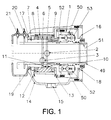
- the component represented in this figure 1 consists of a hollow cylinder (1) which houses in its interior, with a capacity for axial movement, the hollow shaft (49) of the piston which externally forms the piston (50) itself.
- the hollow shaft (1) has a thread (51) for coupling the tool which needs to be used, such as, for example, an hydraulic tie-down.
- the axial movement of the piston (50) and thus that of its hollow shaft (49) is effected by hydraulic pressure.
- the oil under pressure enters alternately through the nozzles (2) and (3), in order to pass on to the annular chambers (5) and (6), from which point it is distributed though ducts to the chambers defined by the piston (50) in the hollow cylinder (1).
- the distribution of the oil is effected through the duct (52) made in the rotary shaft (7) up to one of the chambers, and the annular chamber (6) distributes it by means of a similar duct, which is not visible in the cross-section view of this figure, up to the opposite chamber defined by the piston (50).
- the supply of oil for these chambers is effected through the non-return pressure valves (52 - 53) respectively, which are pilot-operated and work in opposite directions.
- Oil is applied under pressure in an alternating manner, through the nozzles (2) or (3), releasing the pressure of the other nozzle in order to allow the outflow of oil through it.
- hydraulic pressure is applied to one of the chambers which the piston (50) defines, that is, to one side or the other of the piston, in order to thus achieve the axial movement of the hollow shaft (49).
- the oil in the chamber where pressure is not applied leaves through the respective non-return valve, moving though the circuit in a reverse direction in order to return to the hydraulic base.
- the axial position of the hollow shaft (49) is determined by means of the electronic detectors (20) and (21), in order to synchronise the machine during its operation.
- the turning of the rotary shaft (7) is effected on the bearings (8) and (9) of the distribution piece (4) which remains in a fixed position.
- the hydraulic pressure is applied to the annular chamber (5), there is a slight leak or drainage of oil though a small opening existing between the distribution piece (4) and the rotary shaft (7) in the direction indicated by the arrows (10) and (11), in order to allow a smooth rotation of the rotary shaft (7) lubricating its contact with the distribution piece (4).
- This drainage of oil continues its route towards the bearing (9) and the annular chamber (6).
- the oil drained after lubricating bearing (8) or bearing (9) moves in the direction indicated by the arrows (12) and (13) up to the oil catch (14), in order to return it through duct (15) to the deposit of the hydraulic base.
- Oil-breaking catchers are located at the ends of the rotary shaft (7) and the hollow cylinder (1), which prevent any left-over oil from leaking to the outside of the cylinder and, by means of their circular grooves (16) and (17), they conduct the oil to the collection casing (14) through ducts (18) and (19).
- the invention consists of effecting an independent nozzle on the pressure distribution piece between the two annular chambers, which is extended by ducts through which it allows the oil to pass to both bearings, lubricating them simultaneously.
- this nozzle and ducts constitute an alternative channel for the passage of oil, which prevents it from flowing completely towards the chamber which is free from pressure, thus giving rise to the problems mentioned earlier, and which also serves to guide the oil to both bearings simultaneously and independently of whichever annular chamber is under pressure.
- This type of oiling can be optimised, and in fact should be in certain types of hydraulic rotary cylinders, such as, for example, cylinders driving borers and gripping chucks in production or numerical control lathes.
- each bearing On the basis of the independent nozzles and ducts introduced, it is possible for each bearing to have its own channel of lubricating oil supply, which provides a greater supply of this fluid to each bearing and consequently a better lubrication.
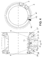
- the invention consists of rendering a nozzle (41) on the pressure distribution piece (4) and between annular chamber (5) and annular chamber (6), also visible in the front section of figure 4.
- This nozzle (41) is extended in duct (42) arranged in a radial direction with respect to the rotation axis of the cylinder, which in turn is connected to the duct (43) arranged in an axial direction, which connects directly to the sides of the bearings (8) and (9), thus constituting a direct channel for the drainage oil to pass on to the bearings (8) and (9).
- a variation has been foreseen in the implementation of the invention, applicable to specific models of rotary cylinders, or in order to adapt to certain applications of the invention.
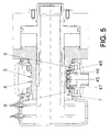
- the channel for the passage of oil is effected in the body of the rotary shaft (7) instead of the pressure distribution piece (4), as is shown in figure 5.
- This channel is constituted in a similar manner by means of the nozzle (45) between the annular chambers (5) and (6), which, in a radial directions, connects with the duct (46) arranged in a linear direction, which in this variation is extended in nozzles (47) and (48), also radial, next to the bearings (8) and (9) to which the oil is supplied, also in a continuous and simultaneous manner.
- the said independent channels achieve an individualised oiling of the bearings, and at the same time allow a regulated and independent drainage of the oil reaching the bearings, for which reason they are oiled more regularly.
- the ducts (60) and (61), with a radial separation between them, are arranged in the rotary shaft (7) and connect respectively with ducts (62) and (63), making independent drainage to the bearing (8) and (9) possible.
Landscapes
- Engineering & Computer Science (AREA)
- Mechanical Engineering (AREA)
- Hydraulic Motors (AREA)
- Gripping On Spindles (AREA)
- Rolling Contact Bearings (AREA)
- Other Liquid Machine Or Engine Such As Wave Power Use (AREA)
- Soil Working Implements (AREA)
- Actuator (AREA)
Applications Claiming Priority (4)
| Application Number | Priority Date | Filing Date | Title |
|---|---|---|---|
| ES9801770A ES2158754B1 (es) | 1998-08-17 | 1998-08-17 | Perfeccionamientos en los cilindros giratorios hidraulicos. |
| ES9801770 | 1998-08-17 | ||
| ES9802537A ES2158762B1 (es) | 1998-08-17 | 1998-12-03 | Perfeccionamientos en los cilindros giratorios hidraulicos. |
| ES9802537 | 1998-12-03 |
Publications (3)
| Publication Number | Publication Date |
|---|---|
| EP0980731A2 true EP0980731A2 (de) | 2000-02-23 |
| EP0980731A3 EP0980731A3 (de) | 2001-05-02 |
| EP0980731B1 EP0980731B1 (de) | 2004-02-11 |
Family
ID=26155172
Family Applications (1)
| Application Number | Title | Priority Date | Filing Date |
|---|---|---|---|
| EP99500148A Expired - Lifetime EP0980731B1 (de) | 1998-08-17 | 1999-08-17 | Verbesserungen an drehenden Hydraulikzylindern |
Country Status (3)
| Country | Link |
|---|---|
| EP (1) | EP0980731B1 (de) |
| AT (1) | ATE259270T1 (de) |
| DE (1) | DE69914689T2 (de) |
Cited By (2)
| Publication number | Priority date | Publication date | Assignee | Title |
|---|---|---|---|---|
| ITTO20120656A1 (it) * | 2012-07-26 | 2014-01-27 | Rotomors Spa | Collettore idraulico per l'azionamento di attrezzature di presa rotanti a comando idraulico |
| CN114059943A (zh) * | 2021-11-19 | 2022-02-18 | 中铁二院工程集团有限责任公司 | 一种千米级水平绳索钻杆同步旋转液压卡盘 |
Family Cites Families (1)
| Publication number | Priority date | Publication date | Assignee | Title |
|---|---|---|---|---|
| US4549822A (en) * | 1983-08-15 | 1985-10-29 | Sms Schloemann-Siemag, Inc. | Apparatus to distribute a highly-pressurized fluid medium |
-
1999
- 1999-08-17 EP EP99500148A patent/EP0980731B1/de not_active Expired - Lifetime
- 1999-08-17 DE DE1999614689 patent/DE69914689T2/de not_active Expired - Fee Related
- 1999-08-17 AT AT99500148T patent/ATE259270T1/de not_active IP Right Cessation
Cited By (2)
| Publication number | Priority date | Publication date | Assignee | Title |
|---|---|---|---|---|
| ITTO20120656A1 (it) * | 2012-07-26 | 2014-01-27 | Rotomors Spa | Collettore idraulico per l'azionamento di attrezzature di presa rotanti a comando idraulico |
| CN114059943A (zh) * | 2021-11-19 | 2022-02-18 | 中铁二院工程集团有限责任公司 | 一种千米级水平绳索钻杆同步旋转液压卡盘 |
Also Published As
| Publication number | Publication date |
|---|---|
| DE69914689D1 (de) | 2004-03-18 |
| EP0980731B1 (de) | 2004-02-11 |
| ATE259270T1 (de) | 2004-02-15 |
| DE69914689T2 (de) | 2005-01-13 |
| EP0980731A3 (de) | 2001-05-02 |
Similar Documents
| Publication | Publication Date | Title |
|---|---|---|
| DE3130871C2 (de) | ||
| US2886346A (en) | Drill head with hydraulic thrust balancing means | |
| US20080135339A1 (en) | Method and apparatus for cooling and lubricating an off-axis motor/generator | |
| US6729813B2 (en) | Spindlehead for tools | |
| US3020990A (en) | Transmissions | |
| KR101934066B1 (ko) | 유성기어장치 | |
| US4723778A (en) | Automatic lubricating system of power chuck | |
| US6929099B2 (en) | Rotary feed-through | |
| US6810772B2 (en) | Automatic transmission | |
| GB2035157A (en) | Hydraulically actuated clamping cylinder for clamping devices on a rotating spindle | |
| EP0980731B1 (de) | Verbesserungen an drehenden Hydraulikzylindern | |
| US5052436A (en) | Device for feeding a fluid to a rotating machine part | |
| JP2000015541A (ja) | 工作機械の主軸装置 | |
| DE112007002529T5 (de) | Variabler Turbolader und Verfahren zum Rückführen von Öl von hydraulischer Antriebseinrichtung | |
| CA1246472A (en) | Fan clutch | |
| JP2524713B2 (ja) | 回転スピンドルにおける固定装置のための油圧操作式シリンダ | |
| EP1963626B1 (de) | Nockenwellenversteller | |
| DK155684B (da) | Hydraulisk tandhjulsmaskine af planettypen | |
| JPS6237276B2 (de) | ||
| JPS6059088B2 (ja) | 環状液圧締め付け装置 | |
| KR0144339B1 (ko) | 자동변속기를 위한 윤활장치 | |
| EP0978350A1 (de) | Vorrichtung für die hauptspindel einer werkzeugmaschine und mehrspindelkopf für werkzeugmaschinen | |
| US4168654A (en) | Fluid supply distributor | |
| US5221098A (en) | Collet closer | |
| CN119468007A (zh) | 可自动控制流量的数控润滑油喷涂装置 |
Legal Events
| Date | Code | Title | Description |
|---|---|---|---|
| PUAI | Public reference made under article 153(3) epc to a published international application that has entered the european phase |
Free format text: ORIGINAL CODE: 0009012 |
|
| AK | Designated contracting states |
Kind code of ref document: A2 Designated state(s): AT BE CH CY DE DK ES FI FR GB GR IE IT LI LU MC NL PT SE |
|
| AX | Request for extension of the european patent |
Free format text: AL;LT;LV;MK;RO;SI |
|
| PUAL | Search report despatched |
Free format text: ORIGINAL CODE: 0009013 |
|
| AK | Designated contracting states |
Kind code of ref document: A3 Designated state(s): AT BE CH CY DE DK ES FI FR GB GR IE IT LI LU MC NL PT SE |
|
| AX | Request for extension of the european patent |
Free format text: AL;LT;LV;MK;RO;SI |
|
| RIC1 | Information provided on ipc code assigned before grant |
Free format text: 7B 23B 31/30 A, 7F 16C 33/66 B |
|
| 17P | Request for examination filed |
Effective date: 20011030 |
|
| AKX | Designation fees paid |
Free format text: AT BE CH CY DE DK ES FI FR GB GR IE IT LI LU MC NL PT SE |
|
| GRAP | Despatch of communication of intention to grant a patent |
Free format text: ORIGINAL CODE: EPIDOSNIGR1 |
|
| GRAS | Grant fee paid |
Free format text: ORIGINAL CODE: EPIDOSNIGR3 |
|
| GRAA | (expected) grant |
Free format text: ORIGINAL CODE: 0009210 |
|
| AK | Designated contracting states |
Kind code of ref document: B1 Designated state(s): AT BE CH CY DE DK ES FI FR GB GR IE IT LI LU MC NL PT SE |
|
| PG25 | Lapsed in a contracting state [announced via postgrant information from national office to epo] |
Ref country code: NL Free format text: LAPSE BECAUSE OF FAILURE TO SUBMIT A TRANSLATION OF THE DESCRIPTION OR TO PAY THE FEE WITHIN THE PRESCRIBED TIME-LIMIT Effective date: 20040211 Ref country code: LI Free format text: LAPSE BECAUSE OF FAILURE TO SUBMIT A TRANSLATION OF THE DESCRIPTION OR TO PAY THE FEE WITHIN THE PRESCRIBED TIME-LIMIT Effective date: 20040211 Ref country code: FI Free format text: LAPSE BECAUSE OF FAILURE TO SUBMIT A TRANSLATION OF THE DESCRIPTION OR TO PAY THE FEE WITHIN THE PRESCRIBED TIME-LIMIT Effective date: 20040211 Ref country code: CY Free format text: LAPSE BECAUSE OF FAILURE TO SUBMIT A TRANSLATION OF THE DESCRIPTION OR TO PAY THE FEE WITHIN THE PRESCRIBED TIME-LIMIT Effective date: 20040211 Ref country code: CH Free format text: LAPSE BECAUSE OF FAILURE TO SUBMIT A TRANSLATION OF THE DESCRIPTION OR TO PAY THE FEE WITHIN THE PRESCRIBED TIME-LIMIT Effective date: 20040211 Ref country code: BE Free format text: LAPSE BECAUSE OF FAILURE TO SUBMIT A TRANSLATION OF THE DESCRIPTION OR TO PAY THE FEE WITHIN THE PRESCRIBED TIME-LIMIT Effective date: 20040211 Ref country code: AT Free format text: LAPSE BECAUSE OF FAILURE TO SUBMIT A TRANSLATION OF THE DESCRIPTION OR TO PAY THE FEE WITHIN THE PRESCRIBED TIME-LIMIT Effective date: 20040211 |
|
| REG | Reference to a national code |
Ref country code: GB Ref legal event code: FG4D |
|
| REG | Reference to a national code |
Ref country code: CH Ref legal event code: EP |
|
| REG | Reference to a national code |
Ref country code: IE Ref legal event code: FG4D |
|
| REF | Corresponds to: |
Ref document number: 69914689 Country of ref document: DE Date of ref document: 20040318 Kind code of ref document: P |
|
| PG25 | Lapsed in a contracting state [announced via postgrant information from national office to epo] |
Ref country code: SE Free format text: LAPSE BECAUSE OF FAILURE TO SUBMIT A TRANSLATION OF THE DESCRIPTION OR TO PAY THE FEE WITHIN THE PRESCRIBED TIME-LIMIT Effective date: 20040511 Ref country code: GR Free format text: LAPSE BECAUSE OF FAILURE TO SUBMIT A TRANSLATION OF THE DESCRIPTION OR TO PAY THE FEE WITHIN THE PRESCRIBED TIME-LIMIT Effective date: 20040511 Ref country code: DK Free format text: LAPSE BECAUSE OF FAILURE TO SUBMIT A TRANSLATION OF THE DESCRIPTION OR TO PAY THE FEE WITHIN THE PRESCRIBED TIME-LIMIT Effective date: 20040511 |
|
| PG25 | Lapsed in a contracting state [announced via postgrant information from national office to epo] |
Ref country code: ES Free format text: LAPSE BECAUSE OF FAILURE TO SUBMIT A TRANSLATION OF THE DESCRIPTION OR TO PAY THE FEE WITHIN THE PRESCRIBED TIME-LIMIT Effective date: 20040522 |
|
| NLV1 | Nl: lapsed or annulled due to failure to fulfill the requirements of art. 29p and 29m of the patents act | ||
| PG25 | Lapsed in a contracting state [announced via postgrant information from national office to epo] |
Ref country code: LU Free format text: LAPSE BECAUSE OF NON-PAYMENT OF DUE FEES Effective date: 20040817 Ref country code: IE Free format text: LAPSE BECAUSE OF NON-PAYMENT OF DUE FEES Effective date: 20040817 |
|
| PG25 | Lapsed in a contracting state [announced via postgrant information from national office to epo] |
Ref country code: MC Free format text: LAPSE BECAUSE OF NON-PAYMENT OF DUE FEES Effective date: 20040831 |
|
| REG | Reference to a national code |
Ref country code: CH Ref legal event code: PL |
|
| ET | Fr: translation filed | ||
| PLBE | No opposition filed within time limit |
Free format text: ORIGINAL CODE: 0009261 |
|
| STAA | Information on the status of an ep patent application or granted ep patent |
Free format text: STATUS: NO OPPOSITION FILED WITHIN TIME LIMIT |
|
| 26N | No opposition filed |
Effective date: 20041112 |
|
| REG | Reference to a national code |
Ref country code: IE Ref legal event code: MM4A |
|
| PGFP | Annual fee paid to national office [announced via postgrant information from national office to epo] |
Ref country code: GB Payment date: 20060809 Year of fee payment: 8 |
|
| PGFP | Annual fee paid to national office [announced via postgrant information from national office to epo] |
Ref country code: FR Payment date: 20060828 Year of fee payment: 8 |
|
| PGFP | Annual fee paid to national office [announced via postgrant information from national office to epo] |
Ref country code: IT Payment date: 20060831 Year of fee payment: 8 |
|
| PGFP | Annual fee paid to national office [announced via postgrant information from national office to epo] |
Ref country code: DE Payment date: 20060929 Year of fee payment: 8 |
|
| PG25 | Lapsed in a contracting state [announced via postgrant information from national office to epo] |
Ref country code: PT Free format text: LAPSE BECAUSE OF NON-PAYMENT OF DUE FEES Effective date: 20040711 |
|
| GBPC | Gb: european patent ceased through non-payment of renewal fee |
Effective date: 20070817 |
|
| REG | Reference to a national code |
Ref country code: FR Ref legal event code: ST Effective date: 20080430 |
|
| PG25 | Lapsed in a contracting state [announced via postgrant information from national office to epo] |
Ref country code: DE Free format text: LAPSE BECAUSE OF NON-PAYMENT OF DUE FEES Effective date: 20080301 |
|
| PG25 | Lapsed in a contracting state [announced via postgrant information from national office to epo] |
Ref country code: FR Free format text: LAPSE BECAUSE OF NON-PAYMENT OF DUE FEES Effective date: 20070831 |
|
| PG25 | Lapsed in a contracting state [announced via postgrant information from national office to epo] |
Ref country code: GB Free format text: LAPSE BECAUSE OF NON-PAYMENT OF DUE FEES Effective date: 20070817 |
|
| PG25 | Lapsed in a contracting state [announced via postgrant information from national office to epo] |
Ref country code: IT Free format text: LAPSE BECAUSE OF NON-PAYMENT OF DUE FEES Effective date: 20070817 |