EP0980464B1 - Bergbauvorrichtung- und verfahren für unterirdische weiche wände - Google Patents
Bergbauvorrichtung- und verfahren für unterirdische weiche wände Download PDFInfo
- Publication number
- EP0980464B1 EP0980464B1 EP98918915A EP98918915A EP0980464B1 EP 0980464 B1 EP0980464 B1 EP 0980464B1 EP 98918915 A EP98918915 A EP 98918915A EP 98918915 A EP98918915 A EP 98918915A EP 0980464 B1 EP0980464 B1 EP 0980464B1
- Authority
- EP
- European Patent Office
- Prior art keywords
- mining
- chamber
- ore
- softwall
- seam
- Prior art date
- Legal status (The legal status is an assumption and is not a legal conclusion. Google has not performed a legal analysis and makes no representation as to the accuracy of the status listed.)
- Expired - Lifetime
Links
- 238000005065 mining Methods 0.000 title claims description 106
- 238000000034 method Methods 0.000 title claims description 13
- 239000012530 fluid Substances 0.000 claims description 16
- 229910052500 inorganic mineral Inorganic materials 0.000 claims description 16
- 239000011707 mineral Substances 0.000 claims description 16
- 239000002002 slurry Substances 0.000 claims description 13
- 239000000463 material Substances 0.000 claims description 9
- 230000035515 penetration Effects 0.000 claims description 5
- 238000002347 injection Methods 0.000 description 16
- 239000007924 injection Substances 0.000 description 16
- XLYOFNOQVPJJNP-UHFFFAOYSA-N water Substances O XLYOFNOQVPJJNP-UHFFFAOYSA-N 0.000 description 8
- 239000011159 matrix material Substances 0.000 description 7
- 229910019142 PO4 Inorganic materials 0.000 description 2
- 238000005056 compaction Methods 0.000 description 2
- 239000012071 phase Substances 0.000 description 2
- 239000010452 phosphate Substances 0.000 description 2
- NBIIXXVUZAFLBC-UHFFFAOYSA-K phosphate Chemical compound [O-]P([O-])([O-])=O NBIIXXVUZAFLBC-UHFFFAOYSA-K 0.000 description 2
- 230000006978 adaptation Effects 0.000 description 1
- 230000000712 assembly Effects 0.000 description 1
- 238000000429 assembly Methods 0.000 description 1
- 238000009412 basement excavation Methods 0.000 description 1
- 239000003795 chemical substances by application Substances 0.000 description 1
- 239000004927 clay Substances 0.000 description 1
- 230000002079 cooperative effect Effects 0.000 description 1
- 230000001351 cycling effect Effects 0.000 description 1
- 238000010790 dilution Methods 0.000 description 1
- 239000012895 dilution Substances 0.000 description 1
- 238000009434 installation Methods 0.000 description 1
- 239000007791 liquid phase Substances 0.000 description 1
- 230000000149 penetrating effect Effects 0.000 description 1
- 238000000926 separation method Methods 0.000 description 1
- 238000010008 shearing Methods 0.000 description 1
- 239000002689 soil Substances 0.000 description 1
- 239000007787 solid Substances 0.000 description 1
- 238000005728 strengthening Methods 0.000 description 1
- 238000011144 upstream manufacturing Methods 0.000 description 1
Images


Classifications
-
- E—FIXED CONSTRUCTIONS
- E21—EARTH OR ROCK DRILLING; MINING
- E21C—MINING OR QUARRYING
- E21C41/00—Methods of underground or surface mining; Layouts therefor
- E21C41/16—Methods of underground mining; Layouts therefor
-
- E—FIXED CONSTRUCTIONS
- E21—EARTH OR ROCK DRILLING; MINING
- E21C—MINING OR QUARRYING
- E21C25/00—Cutting machines, i.e. for making slits approximately parallel or perpendicular to the seam
- E21C25/60—Slitting by jets of water or other liquid
Definitions
- This invention pertains in general to the field of mining and, in particular, to a novel device and method for mining slurryable, shallow mineral deposits with earthy overburden in a longwall fashion.
- Underground mining is and has historically been employed to recover stratified minerals under overburden to economic depths.
- Underground mining is traditionally employed when overburden depths exceed those economically removable by surface mining or when major surface disturbance is unacceptable.
- the present invention provides a means for mining slurryable ore reserves where overburden is earthy. Floor conditions are also reduced being an insignificant issue.
- This prior German patent describes a single shield like structural member, having a channel cross-section open to the working face of the mine.
- the structure carries high pressure hydraulic nozzles which project towards the working face.
- the structure is advanceable towards the working face and is inclined in the backward direction for permitting caving-in roof to slide downwards therethrough.
- a device for mining minerals comprising a weight-bearing shell having substantially-parallel, horizontal roof and floor panels integrally connected such as to define a horizontal shell; a movable chamber having substantially-parallel, horizontal top and bottom sections integrally connected such as to define a horizontal sluicing chamber with leading edges adapted for penetration into a seam of ore, said chamber being telescopically coupled to said shell and including means for mining ore; and means for extending and retracting said chamber relative to said shell.
- the moveable chamber may comprise an auger to promote evacuation of ore from the device.
- the mining is accomplished by advancing a plurality of sets of said softwall mining devices positioned at various elevations in the seam as follows:
- the subject invention is directed at phosphate matrix mining.
- a plurality of elongated, substantially parallel, main trenches extend the full length of area to be mined.
- the trenches are nominally 304.8 metres (1,000 feet) apart.
- Heading trenches substantially perpendicular to the main panel trenches are excavated for placement and removal of the mining equipment.
- the trenches are formed by excavating the overburden materials to the top surface of the mineral bed.
- the mineral bed in the trench is separately excavated and beneficially recovered.
- Trench side wall slopes are as steep as is geologically reasonable and safe to minimize excavation.
- Forming a header trench leaves an exposed longwall.
- the softwall mining equipment is installed in the header trench.
- the phosphate is then mined, for example, by slurrying the ore as the mining equipment moves in a direction generally parallel to the main panel trenches.
- the slurried ore flows into the main panel trenches where it is removed to the surface for processing.
- the softwall mining equipment includes an outer shell to support the overburden stresses. Forward motion is created by extending a cutting head into the ore reserve and retracting said head in such a manner as to pull the outer shell forward.
- Unsupported overburden behind the outer shell is encouraged to fill the cavity.
- materials are injected through the outer shell. operation of the softwall equipment and backfilling is performed automatically from controls in the trench or on the surface.
- the equipment can be repositioned at the exit header and again advanced in the opposite direction to mine the next lower level of the ore seam.
- Another alternative would be to utilize several sets of softwall mining equipment in a seam thicker than one set of equipment can mine.
- the uppermost level would be mined first.
- Adjacent lower levels would be mined with predetermined horizontal separation distances between sets of equipment.
- a single main trench can be used with a header constructed in a "T" manner.
- One set of softwall mining equipment would be placed in each header branch of the "T” with slurried ore feed to the trunk main panel trench.
- the equipment can also operate in a spiral fashion following main panel trenches constructed to curl in a continuous pattern through the ore reserve.
- the 0 softwall mining device of the present invention is also believed:
- FIG. 1 is an isometric schematic view of a softwall mining device 10 according to the invention.
- the device 10 consists of a face sluicing chamber 20 partially enclosed within a rear and rear bearing support or shell 22.
- the function of the device 10 is to remove ore matrix away from the ore face. This is accomplished by the forward extension of the face sluicing chamber 20 from within the rear bearing support 22 through the actuation of an extension ram 24.
- extension guides 26 provide directional thrust control for the device's forward movement.
- a plurality of rigidly mounted support braces 30 provide vertical strength to the face sluicing chamber 20.
- a retractable and extendable rotating ram or guide 38, pivotally mounted to both the face sluicing chamber 20 and the extension and support assembly 28, provides vertical movement control.
- a plurality of rear injectors 31 extend through the rear bearing support 22 to apply fluids into the collapsed overburden.
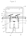
- Fig. 2 shows the softwall mining device 10 in plan view.
- the extension and retraction of the face sluicing chamber 20 from the rear bearing support 22 is provided by the extension ram 24 attached fixedly to the rear bearing support 22 and pivotally to the extension and support assembly 28.
- the extension and support assembly 28 is attached slidingly to both extension guides 26 by means of a plurality of extension and support guide bearing assemblies 25 and directly to the inclined vertical rotating ram 38.
- a plurality of pressurized water supply lines and electrical controls 21 (Fig. 3) and water injection control units 34 are attached to face sluicing chamber 20 to provide control of injection fluid pressure and volume.
- a plurality of pressurized, angularly mounted, injection nozzles 32 fed from each water injection control unit 34 is mounted on the face sluicing chamber 20 to supply fluid injection within the enclosure of the face sluicing chamber 20.
- Fig. 3 is a schematic representation of the cross section of the mining equipment 10.
- the leading edge of a rear bearing support 22 is typically beveled to reduce forward resistance.
- the inclined rotating guide 38 is fixedly connected to the rear portion of the face sluicing chamber 20.
- a rigid support post 37 is rigidly mounted to the floor and roof of the rear bearing support 22 for strengthening the device.
- a softwall system control line alignment hole 33 is provided in the extension guides 28.
- Overlapping side covers 27 are rigidly connected to the rear bearing support 22 to reduce the likelihood of foreign materials entering the device when used in combination with other softwall mining devices.
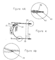
- Fig. 4 shows a more detailed side view of the face sluicing chamber 20, with enlarged details shown in Figs. 4A and 4B.
- Pressurized injection fluid is delivered to the plurality of water injection control units 34 through the series of pressurized water supply lines and electrical controls 21.
- the water injection control units 34 are mounted on the outside surface of the face sluicing chamber 20 and distribute pressurized injection fluids to the respective pressurized injection nozzles 32 inside the face sluicing chamber 20.
- a plurality of nozzles 32 is mounted inside the face sluicing chamber 20 to inject fluids into the ore to break ore from its insitu condition and create a slurry.
- the face sluicing chamber 20 is machined with a channel inner plate water conduit 42 (Fig.
- a face sluicing chamber seal 39 (Fig. 4B) provides a seat to prevent external materials from entering the enclosure of the rear bearing support 22.
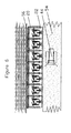
- Fig. 5 shows in perspective view a plurality of softwall mining devices 10 connected with a softwall system control line 29 through the softwall system control line alignment holes 33.
- the softwall system control line 29 is secured with a constant tensioning device 64 flexibly attached to the most upstream device in the slurry flow.
- Adjoining devices 10 are provided with overlapping seals 23 and 36 to minimize leakage of foreign materials into the devices.
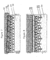
- Figs. 6 through 8 refer to the operation of the softwall mining devices 10 of the invention. There are a number of ways the devices of the invention can be operated. The following illustrations are not meant to be exhaustive but rather to illustrate only some of the possible ways and sequences in which they can be used to recover ore slurry material.
- Fig. 6 is a schematic representation in plan view of the first step in the operation of the softwall mining devices 10.
- the devices are assembled along an ore matrix mining face 56 with full retraction of the face sluicing chambers 20 in preparation for an extension push into the ore matrix mining face 56 against a subsided earthy overburden 54.
- Surface compaction equipment 44 could be used on the surface for additional overburden compaction.
- Fig. 7 is a schematic representation in plan view of a possible second step in the operation of the devices 10 showing an advance sequence of the face sluicing chamber 20 illustrated by numerals 61 against the uniform alignment of adjacent rear bearing supports 22 bearing against the subsided earthy overburden 54.
- Fig. 8 is a schematic representation showing a third step in the operation of the softwall mining devices 10 in plan view.
- the support units of the rear bearing supports 22 are advanced (i.e., retracted toward the sluicing chambers) in a sequence shown by numerals 63 to illustrate the direction of mining advance, thereby causing subsidence of the earthy overburden 54 behind the devices 10.
- the three steps of the mining cycle illustrated above are repeated to provide uninterrupted mining and flow of ore from the mining face.
- the cycling of the steps will occur in batches among groups of devices feeding multiple main entries at various points along the mining face such that all three steps are simultaneous at different positions along the face to secure its uniform advancement.
- the 3 steps to the mining cycle are repeated to provide uninterrupted mining and flow of ore from the mining face.
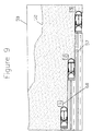
- Fig. 9 shows a multiple lift mining sequence 68 with a softwall mining device 10 or a set of devices in an ore body thicker than the device's height. Subsidence of the original overburden surface 50 will occur in stair-step fashion possibly producing a subsided surface 52 as the ore matrix 57 is removed.
- Fig. 10 illustrates the use of a plurality of softwall mining devices 10 with two parallel main trenches 60 and a perpendicular header trench 66 extending the full distance of the panel width 59.
- a plurality of adjacent softwall mining devices 10 progresses more or less parallel to the ore matrix mining face 56.
- a closed end 58 in a face sluicing chamber 20 in the middle of the face divides the header trench 66 forcing the slurried ore to follow the flow directions 65 toward the mains 60, where slurried ore is collected by trench-gate slurry handling equipment 62 placed at each main trenches end for transport and processing.
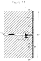
- Fig. 11 shows the use of a plurality of softwall mining devices 10 using an alternative "T" trench configuration with two header trenches 66 feeding into a single main trench 60 excavated during the mine development phase.
Landscapes
- Engineering & Computer Science (AREA)
- Mining & Mineral Resources (AREA)
- Geology (AREA)
- Life Sciences & Earth Sciences (AREA)
- General Life Sciences & Earth Sciences (AREA)
- Geochemistry & Mineralogy (AREA)
- Remote Sensing (AREA)
- Mechanical Engineering (AREA)
- Drilling And Exploitation, And Mining Machines And Methods (AREA)
- Manufacture And Refinement Of Metals (AREA)
- Excavating Of Shafts Or Tunnels (AREA)
- Disintegrating Or Milling (AREA)
- Bulkheads Adapted To Foundation Construction (AREA)
Claims (16)
- Vorrichtung zum Abbau von Mineralien mit:einem lasttragenden Gehäuse (22), das im wesentlichen parallele horizontale Deck- und Bodenplatten aufweist, die fest miteinander verbunden sind, so daß ein horizontales Gehäuse (22) gebildet ist;einer beweglichen Kammer (20), die im wesentlichen parallele, horizontale obere und untere Abschnitte aufweist, die fest miteinander verbunden sind, so daß eine horizontale Rinnenwaschkammer (20) mit Vorderkanten gebildet ist, die geeignet sind, in ein Flöz aus Erz einzudringen,
dadurch gekennzeichnet, daß die Kammer (20) teleskopisch mit dem Gehäuse (22) verbunden ist und Vorrichtungen zum Abbau von Erz enthält; undVorrichtungen (24, 25, 26, 28) zum Ausfahren und Einfahren der Kammer (20) relativ zu dem Gehäuse (22) . - Vorrichtung zum Abbau von Mineralien nach Anspruch 1,
bei der die Deck- und Bodenplatten des Gehäuses (22) und die oberen und unteren Abschnitte der Kammer (20) teleskopartig ineinandergreifen und die Kammer (20) einen im wesentlichen halbzylindrischen hinteren Abschnitt aufweist. - Vorrichtung zum Abbau von Mineralien nach Anspruch 1,
bei der die Vorrichtung zum Ausfahren und Einfahren der Kammer (20) relativ zu dem Gehäuse (22) einen hydraulischen Arbeitszylinder (24) enthält. - Vorrichtung zum Abbau von Mineralien nach Anspruch 1,
ferner mit einer Vorrichtung (34; 35) zum Spritzen von Flüssigkeiten aus den Vorderkanten (40) der Kammer (20), um das Vorrücken der Vorrichtung zu erleichtern. - Vorrichtung zum Abbau von Mineralien nach Anspruch 1,
bei der die Vorrichtung zum Abbau von Erz eine Vorrichtung (32, 34) zum Spritzen von Flüssigkeiten'in der Kammer (20) enthält, um das Erz aufzuschlämmen. - Vorrichtung zum Abbau von Mineralien nach Anspruch 1,
bei der die Kammer (20) eine Schnecke enthält, um den Abtransport von Erz aus der Vorrichtung zu beschleunigen. - Vorrichtung zum Abbau von Mineralien nach Anspruch 1,
ferner mit heckseitig angeordneten Injektoren (31) zum Auswerfen von Material in die einstürzende Deckschicht. - Vorrichtung zum Abbau von Mineralien nach Anspruch 1,
bei der die Vorderkanten (40) der Kammer (20) im wesentlichen fluchtend zu einer vorderen Öffnung des Gehäuses (22) ausgerichtet sind, wenn die Kammer (20) eingefahren ist, und die Vorderkanten der Kammer (20) relativ zu der vorderen Öffnung des Gehäuses (22) nach außen vorstehen, wenn die Kammer (20) ausgefahren ist. - Verfahren zum Abbau von Mineralien aus einem unter einer Deckschicht aus Erde liegenden Flöz aus schlämmbarem Erz mit den folgenden Verfahrensschritten:a) Ausbilden eines langgestreckten ersten Grabens (60) einer ersten vorgegebenen Breite bis zu einer Tiefe, die im wesentlichen gleich der Sohle des Flözes ist;b) Ausbilden eines zweiten langgestreckten Grabens (66) einer zweiten vorgegebenen Breite, der im wesentlichen senkrecht zu dem ersten Graben angeordnet ist und mit einem Ende an ein Ende des ersten Grabens (60) angrenzt, so daß ein Softwall-Abbaustoß gebildet ist;c) Anordnen einer Vielzahl von Softwall-Abbauvorrichtungen, die an einem Abbaustoß des Flözes in dem zweiten Graben anliegen, wobei jede Vorrichtung ein lasttragendes Gehäuse (22) umfaßt, das im wesentlichen parallele, horizontale Deck- und Bodenplatten aufweist, die fest miteinander verbunden sind, so daß ein horizontales Gehäuse gebildet ist; gekennzeichnet durch eine bewegliche Kammer (20), die im wesentlichen parallele, horizontale obere und untere Abschnitte aufweist, die fest miteinander verbunden sind, so daß eine horizontale Rinnenwaschkammer (20) mit Vorderkanten (40) gebildet ist, die geeignet sind, in ein Flöz aus Erz einzudringen, wobei die Kammer (20) teleskopisch mit dem Gehäuse (22) verbunden ist und Vorrichtungen zum Abbau von Erz enthält; und Vorrichtungen (24, 25, 26, 28) zum Ausfahren und Einfahren der Kammer (20) relativ zu dem Gehäuse (22); undd) Vorwärtsbewegen der Softwall-Abbauvorrichtungen in eine im wesentlichen senkrecht zu dem zweiten Graben verlaufende Richtung, um das Flöz dadurch abzubauen, daß die Kammern (20) benachbarter Vorrichtungen nacheinander vorwärtsbewegt werden.
- Verfahren nach Anspruch 9,
bei dem der Abbau dadurch erfolgt, daß mehrere Gruppen der Softwall-Abbauvorrichtungen in unterschiedlichen Höhen in dem Flöz wie folgt positioniert sind:i. Anordnen einer ersten Gruppe von Softwall-Abbauvorrichtungen zum Ausschlämmen von Erz von einer Oberseite des Flözes bis zu einer Basis der ersten Gruppe der Softwall-Abbauvorrichtungen;ii. Anordnen einer zweiten Gruppe von Softwall-Abbauvorrichtungen zum Ausschlämmen von Erz von der Basis der ersten Gruppe von Softwall-Abbauvorrichtungen bis zu einer Basis der zweiten Gruppe von Softwall-Abbauvorrichtungen; undiii. Anordnen einer zusätzlichen Gruppe von Softwall-Abbauvorrichtungen zum Ausschlämmen von Erz von einer Basis einer unmittelbar höheren Gruppe von Softwall-Abbauvorrichtungen zu einer Basis eines vorhergehenden Arbeitsganges, bis die Erzader in einem vorgegebenen Maße abgebaut ist. - Verfahren nach Anspruch 9,
bei dem der Abbau wie folgt durchgeführt wird:i. Anordnen einer Gruppe von Softwall-Abbauvorrichtungen zum Ausschlämmen von Erz von einer Oberseite des Flözes;ii. Vorrücken mit der Gruppe von Softwall-Abbauvorrichtungen über eine vorgegebene Distanz durch das Flöz;iii. Wiederanordnen der Gruppe von Softwall-Abbauvorrichtungen auf einer neuen, durch Verfahrensschritt ii gebildeten Oberseite des Flözes;iv. Vorrücken mit der Gruppe von Softwall-Abbauvorrichtungen über eine vorgegebene Distanz durch das Flöz; undv. Wiederanordnen der Gruppe von Softwall-Abbauvorrichtungen auf einer neuen, durch Verfahrensschritt iv gebildeten Oberseite des Flözes;vi. Wiederholen der Verfahrensschritte iv und v, bis eine vorgegebene. Menge des Flözes entfernt worden ist. - Verfahren nach Anspruch 9,
bei dem ein dritter langgestreckter Graben im wesentlichen parallel zu dem ersten Graben und am anderen Ende des zweiten Grabens, das nicht mit dem ersten Graben verbunden ist, ausgebildet wird, um einen Austritt für ausgeschlämmtes abgebautes Mineral in den ersten oder den dritten Graben oder in beide Gräben zu schaffen. - Verfahren nach Anspruch 9,
ferner mit dem Verfahrensschritt des Vorsehens von heckseitig angeordneten Injektoren (31) an dem lasttragenden Gehäuse (22) und Auswerfen von flüssigem Material aus diesen in die einstürzende Deckschicht (54). - Verfahren nach Anspruch 9,
ferner mit dem Verfahrensschritt des Spritzens von Flüssigkeiten aus den Vorderkanten (40) der Kammer (20), um das Vorrücken der Vorrichtung zu erleichtern. - Verfahren nach Anspruch 9,
ferner mit dem Verfahrensschritt des Spritzens von Flüssigkeiten in der Kammer (20) zum Aufschlämmen von Erz. - Verfahren nach Anspruch 9,
ferner mit dem Verfahrensschritt des Anordnens einer Schnecke in der Rinnenwaschkammer (20), um den Abtransport von geschlämmtem Erz aus der Vorrichtung zu beschleunigen.
Applications Claiming Priority (3)
| Application Number | Priority Date | Filing Date | Title |
|---|---|---|---|
| US85168097A | 1997-05-06 | 1997-05-06 | |
| US851680 | 1997-05-06 | ||
| PCT/US1998/008891 WO1998050682A1 (en) | 1997-05-06 | 1998-05-01 | Softwall mining method and device |
Publications (2)
| Publication Number | Publication Date |
|---|---|
| EP0980464A1 EP0980464A1 (de) | 2000-02-23 |
| EP0980464B1 true EP0980464B1 (de) | 2004-01-14 |
Family
ID=25311387
Family Applications (1)
| Application Number | Title | Priority Date | Filing Date |
|---|---|---|---|
| EP98918915A Expired - Lifetime EP0980464B1 (de) | 1997-05-06 | 1998-05-01 | Bergbauvorrichtung- und verfahren für unterirdische weiche wände |
Country Status (11)
| Country | Link |
|---|---|
| US (1) | US6086159A (de) |
| EP (1) | EP0980464B1 (de) |
| AP (1) | AP1240A (de) |
| AT (1) | ATE257903T1 (de) |
| AU (1) | AU730204B2 (de) |
| BR (1) | BR9809219A (de) |
| CA (1) | CA2289269C (de) |
| DE (1) | DE69821104T2 (de) |
| ID (1) | ID23782A (de) |
| IL (1) | IL132605A0 (de) |
| WO (1) | WO1998050682A1 (de) |
Families Citing this family (4)
| Publication number | Priority date | Publication date | Assignee | Title |
|---|---|---|---|---|
| US6796616B2 (en) * | 2002-06-26 | 2004-09-28 | Jeffrey K. Harman | Mining system |
| US8672415B2 (en) | 2010-04-16 | 2014-03-18 | Joy Mm Delaware, Inc. | Advancing longwall system for surface mining |
| PL402402A1 (pl) | 2010-07-09 | 2013-07-22 | Joy Mm Delaware, Inc. | System górniczy do ciaglego wybierania |
| MA63865B1 (fr) * | 2024-01-15 | 2025-09-30 | Bahraoui Elhassan El | Système et méthode d’exploitation minière verte utilisant une plateforme automatisée mobile |
Family Cites Families (9)
| Publication number | Priority date | Publication date | Assignee | Title |
|---|---|---|---|---|
| US3790214A (en) * | 1972-09-29 | 1974-02-05 | O Kilroy | Hydraulic mining system |
| DE2307413C2 (de) * | 1973-02-15 | 1980-02-14 | Thyssen Industrie Ag, 4300 Essen | Vorrichtung fur die Hereingewinnung einer flozartigen Lagerstatte im Strebbau |
| US4017122A (en) | 1976-06-23 | 1977-04-12 | Acres Consulting Services Limited | Longwall trench mining system |
| DE2751790C2 (de) * | 1977-11-19 | 1986-01-23 | Gewerkschaft Eisenhütte Westfalia, 4670 Lünen | Einrichtung zum Vorschneiden eines Hangend- und/oder Liegendschlitzes bei der kombinierten mechanischen und hydraulischen Gewinnung von Kohle u.dgl. |
| DE2929153A1 (de) * | 1979-07-19 | 1981-02-12 | Gewerk Eisenhuette Westfalia | Abbaueinrichtung fuer den untertage- bergbau |
| SU1122820A1 (ru) * | 1983-02-04 | 1984-11-07 | Всесоюзный научно-исследовательский и проектно-конструкторский институт добычи угля гидравлическим способом | Исполнительный орган фронтального выемочного агрегата |
| DE3319662A1 (de) * | 1983-05-31 | 1984-12-06 | Hanns-André 3370 Seesen Pitot | Vorrichtung zum abbau von kohle in steiler oder stark geneigter lagerung |
| SU1629540A1 (ru) * | 1989-02-08 | 1991-02-23 | Институт Горного Дела Ан Казсср | Способ создани искусственной кровли при слоевой выемке мощного пласта |
| SU1652540A1 (ru) * | 1989-02-20 | 1991-05-30 | Шахтинский научно-исследовательский и проектно-конструкторский угольный институт им.А.М.Терпигорева | Приводна станци струговой установки |
-
1998
- 1998-05-01 EP EP98918915A patent/EP0980464B1/de not_active Expired - Lifetime
- 1998-05-01 AU AU71743/98A patent/AU730204B2/en not_active Ceased
- 1998-05-01 WO PCT/US1998/008891 patent/WO1998050682A1/en not_active Ceased
- 1998-05-01 AP APAP/P/1999/001679A patent/AP1240A/en active
- 1998-05-01 BR BR9809219-7A patent/BR9809219A/pt not_active IP Right Cessation
- 1998-05-01 AT AT98918915T patent/ATE257903T1/de not_active IP Right Cessation
- 1998-05-01 DE DE69821104T patent/DE69821104T2/de not_active Expired - Fee Related
- 1998-05-01 CA CA002289269A patent/CA2289269C/en not_active Expired - Fee Related
- 1998-05-01 ID IDW991299A patent/ID23782A/id unknown
- 1998-05-01 IL IL13260598A patent/IL132605A0/xx unknown
-
1999
- 1999-04-07 US US09/287,885 patent/US6086159A/en not_active Expired - Fee Related
Also Published As
| Publication number | Publication date |
|---|---|
| AP1240A (en) | 2004-01-30 |
| DE69821104D1 (de) | 2004-02-19 |
| DE69821104T2 (de) | 2004-11-11 |
| BR9809219A (pt) | 2000-07-04 |
| CA2289269A1 (en) | 1998-11-12 |
| AP9901679A0 (en) | 1999-12-31 |
| EP0980464A1 (de) | 2000-02-23 |
| US6086159A (en) | 2000-07-11 |
| AU730204B2 (en) | 2001-03-01 |
| WO1998050682A1 (en) | 1998-11-12 |
| ID23782A (id) | 2000-05-11 |
| AU7174398A (en) | 1998-11-27 |
| ATE257903T1 (de) | 2004-01-15 |
| CA2289269C (en) | 2006-08-01 |
| IL132605A0 (en) | 2001-03-19 |
Similar Documents
| Publication | Publication Date | Title |
|---|---|---|
| RU2123600C1 (ru) | Способ непрерывной выемки агрегатного материала из пласта и устройство для его осуществления | |
| CN207229105U (zh) | 一种沉井法竖井掘进机 | |
| CN100523432C (zh) | 开采方法和开采系统 | |
| US4076311A (en) | Hydraulic mining from tunnel by reciprocated pipes | |
| US5180251A (en) | Underground protection underneath a dump | |
| US3887235A (en) | Assembly for hydraulic extraction of sheet-like mineral deposits sectioned into panels by a system of passageways | |
| EP0980464B1 (de) | Bergbauvorrichtung- und verfahren für unterirdische weiche wände | |
| US6505892B1 (en) | Softwall mining method and device | |
| US8608410B2 (en) | Apparatus and a method for constructing an underground curved multisectional wall and stratum | |
| RU2212536C1 (ru) | Способ разработки мощных крутых и крутонаклонных угольных пластов | |
| RU2168629C1 (ru) | Способ разработки мощного пологого угольного пласта | |
| EP0257652A1 (de) | Verfahren und Vorrichtung zum Vortrieb einer in das Liegende eines Flözes gelegten Abbau- bzw. Flözstrecke | |
| MXPA99009909A (en) | Softwall mining method and device | |
| CA1167316A (en) | Blasting installation including guided carriage with drilling and explosing loading means | |
| RU2151294C1 (ru) | Способ разработки мощного крутого угольного пласта горизонтальными слоями | |
| Klenowski et al. | Development of support systems for longwall mining in the Bowen Basin, Central Queensland | |
| CA2615801C (en) | Narrow bench mining system | |
| CN117967343B (zh) | 掘锚一体机 | |
| RU2013549C1 (ru) | Способ возведения искусственного межгоризонтального целика при разработке крутых и наклонных пластов | |
| HU192450B (en) | Method and apparatus for mining steep mineral bed particularly steep coal one | |
| SU1244315A1 (ru) | Способ гидромеханической выемки крутых угольных пластов столбами по падению и устройство дл его осуществлени | |
| CN109538204B (zh) | 矿料机械化连续生产方法 | |
| RU1788256C (ru) | Способ разработки крутых и наклонных угольных пластов средней мощности | |
| SU1728488A1 (ru) | Способ разработки угольных пластов | |
| SU1090887A1 (ru) | Способ выемки выбросоопасных пластов и устройство дл его осуществлени |
Legal Events
| Date | Code | Title | Description |
|---|---|---|---|
| PUAI | Public reference made under article 153(3) epc to a published international application that has entered the european phase |
Free format text: ORIGINAL CODE: 0009012 |
|
| 17P | Request for examination filed |
Effective date: 19991118 |
|
| AK | Designated contracting states |
Kind code of ref document: A1 Designated state(s): AT BE CH CY DE DK ES FI FR GB GR IE IT LI LU MC NL PT SE |
|
| 17Q | First examination report despatched |
Effective date: 20021127 |
|
| GRAH | Despatch of communication of intention to grant a patent |
Free format text: ORIGINAL CODE: EPIDOS IGRA |
|
| GRAS | Grant fee paid |
Free format text: ORIGINAL CODE: EPIDOSNIGR3 |
|
| GRAA | (expected) grant |
Free format text: ORIGINAL CODE: 0009210 |
|
| AK | Designated contracting states |
Kind code of ref document: B1 Designated state(s): AT BE CH CY DE DK ES FI FR GB GR IE IT LI LU MC NL PT SE |
|
| PG25 | Lapsed in a contracting state [announced via postgrant information from national office to epo] |
Ref country code: NL Free format text: LAPSE BECAUSE OF FAILURE TO SUBMIT A TRANSLATION OF THE DESCRIPTION OR TO PAY THE FEE WITHIN THE PRESCRIBED TIME-LIMIT Effective date: 20040114 Ref country code: LI Free format text: LAPSE BECAUSE OF FAILURE TO SUBMIT A TRANSLATION OF THE DESCRIPTION OR TO PAY THE FEE WITHIN THE PRESCRIBED TIME-LIMIT Effective date: 20040114 Ref country code: IT Free format text: LAPSE BECAUSE OF FAILURE TO SUBMIT A TRANSLATION OF THE DESCRIPTION OR TO PAY THE FEE WITHIN THE PRE;WARNING: LAPSES OF ITALIAN PATENTS WITH EFFECTIVE DATE BEFORE 2007 MAY HAVE OCCURRED AT ANY TIME BEFORE 2007. THE CORRECT EFFECTIVE DATE MAY BE DIFFERENT FROM THE ONE RECORDED.SCRIBED TIME-LIMIT Effective date: 20040114 Ref country code: FR Free format text: LAPSE BECAUSE OF FAILURE TO SUBMIT A TRANSLATION OF THE DESCRIPTION OR TO PAY THE FEE WITHIN THE PRESCRIBED TIME-LIMIT Effective date: 20040114 Ref country code: FI Free format text: LAPSE BECAUSE OF FAILURE TO SUBMIT A TRANSLATION OF THE DESCRIPTION OR TO PAY THE FEE WITHIN THE PRESCRIBED TIME-LIMIT Effective date: 20040114 Ref country code: CY Free format text: LAPSE BECAUSE OF FAILURE TO SUBMIT A TRANSLATION OF THE DESCRIPTION OR TO PAY THE FEE WITHIN THE PRESCRIBED TIME-LIMIT Effective date: 20040114 Ref country code: CH Free format text: LAPSE BECAUSE OF FAILURE TO SUBMIT A TRANSLATION OF THE DESCRIPTION OR TO PAY THE FEE WITHIN THE PRESCRIBED TIME-LIMIT Effective date: 20040114 Ref country code: AT Free format text: LAPSE BECAUSE OF FAILURE TO SUBMIT A TRANSLATION OF THE DESCRIPTION OR TO PAY THE FEE WITHIN THE PRESCRIBED TIME-LIMIT Effective date: 20040114 |
|
| REG | Reference to a national code |
Ref country code: GB Ref legal event code: FG4D |
|
| REG | Reference to a national code |
Ref country code: CH Ref legal event code: EP |
|
| REG | Reference to a national code |
Ref country code: IE Ref legal event code: FG4D |
|
| REF | Corresponds to: |
Ref document number: 69821104 Country of ref document: DE Date of ref document: 20040219 Kind code of ref document: P |
|
| PG25 | Lapsed in a contracting state [announced via postgrant information from national office to epo] |
Ref country code: SE Free format text: LAPSE BECAUSE OF FAILURE TO SUBMIT A TRANSLATION OF THE DESCRIPTION OR TO PAY THE FEE WITHIN THE PRESCRIBED TIME-LIMIT Effective date: 20040414 Ref country code: GR Free format text: LAPSE BECAUSE OF FAILURE TO SUBMIT A TRANSLATION OF THE DESCRIPTION OR TO PAY THE FEE WITHIN THE PRESCRIBED TIME-LIMIT Effective date: 20040414 Ref country code: DK Free format text: LAPSE BECAUSE OF FAILURE TO SUBMIT A TRANSLATION OF THE DESCRIPTION OR TO PAY THE FEE WITHIN THE PRESCRIBED TIME-LIMIT Effective date: 20040414 |
|
| PG25 | Lapsed in a contracting state [announced via postgrant information from national office to epo] |
Ref country code: ES Free format text: LAPSE BECAUSE OF FAILURE TO SUBMIT A TRANSLATION OF THE DESCRIPTION OR TO PAY THE FEE WITHIN THE PRESCRIBED TIME-LIMIT Effective date: 20040425 |
|
| PG25 | Lapsed in a contracting state [announced via postgrant information from national office to epo] |
Ref country code: LU Free format text: LAPSE BECAUSE OF NON-PAYMENT OF DUE FEES Effective date: 20040501 |
|
| PG25 | Lapsed in a contracting state [announced via postgrant information from national office to epo] |
Ref country code: IE Free format text: LAPSE BECAUSE OF NON-PAYMENT OF DUE FEES Effective date: 20040504 |
|
| PG25 | Lapsed in a contracting state [announced via postgrant information from national office to epo] |
Ref country code: MC Free format text: LAPSE BECAUSE OF NON-PAYMENT OF DUE FEES Effective date: 20040531 |
|
| NLV1 | Nl: lapsed or annulled due to failure to fulfill the requirements of art. 29p and 29m of the patents act | ||
| REG | Reference to a national code |
Ref country code: CH Ref legal event code: PL |
|
| PLBE | No opposition filed within time limit |
Free format text: ORIGINAL CODE: 0009261 |
|
| STAA | Information on the status of an ep patent application or granted ep patent |
Free format text: STATUS: NO OPPOSITION FILED WITHIN TIME LIMIT |
|
| 26N | No opposition filed |
Effective date: 20041015 |
|
| EN | Fr: translation not filed | ||
| REG | Reference to a national code |
Ref country code: IE Ref legal event code: MM4A |
|
| PGFP | Annual fee paid to national office [announced via postgrant information from national office to epo] |
Ref country code: GB Payment date: 20060412 Year of fee payment: 9 |
|
| PGFP | Annual fee paid to national office [announced via postgrant information from national office to epo] |
Ref country code: BE Payment date: 20060502 Year of fee payment: 9 |
|
| PGFP | Annual fee paid to national office [announced via postgrant information from national office to epo] |
Ref country code: DE Payment date: 20060519 Year of fee payment: 9 |
|
| BERE | Be: lapsed |
Owner name: *IMC-AGRICO CY Effective date: 20070531 |
|
| PG25 | Lapsed in a contracting state [announced via postgrant information from national office to epo] |
Ref country code: PT Free format text: LAPSE BECAUSE OF NON-PAYMENT OF DUE FEES Effective date: 20040614 |
|
| GBPC | Gb: european patent ceased through non-payment of renewal fee |
Effective date: 20070501 |
|
| PG25 | Lapsed in a contracting state [announced via postgrant information from national office to epo] |
Ref country code: BE Free format text: LAPSE BECAUSE OF NON-PAYMENT OF DUE FEES Effective date: 20070531 |
|
| PG25 | Lapsed in a contracting state [announced via postgrant information from national office to epo] |
Ref country code: DE Free format text: LAPSE BECAUSE OF NON-PAYMENT OF DUE FEES Effective date: 20071201 |
|
| PG25 | Lapsed in a contracting state [announced via postgrant information from national office to epo] |
Ref country code: GB Free format text: LAPSE BECAUSE OF NON-PAYMENT OF DUE FEES Effective date: 20070501 |