EP0980328B1 - Shiploader system - Google Patents
Shiploader system Download PDFInfo
- Publication number
- EP0980328B1 EP0980328B1 EP98921141A EP98921141A EP0980328B1 EP 0980328 B1 EP0980328 B1 EP 0980328B1 EP 98921141 A EP98921141 A EP 98921141A EP 98921141 A EP98921141 A EP 98921141A EP 0980328 B1 EP0980328 B1 EP 0980328B1
- Authority
- EP
- European Patent Office
- Prior art keywords
- conveying means
- slewing
- bridge
- runway
- conveyor
- Prior art date
- Legal status (The legal status is an assumption and is not a legal conclusion. Google has not performed a legal analysis and makes no representation as to the accuracy of the status listed.)
- Expired - Lifetime
Links
- 239000000463 material Substances 0.000 claims abstract description 77
- 238000013459 approach Methods 0.000 claims abstract description 50
- 238000000034 method Methods 0.000 claims abstract description 11
- 238000007599 discharging Methods 0.000 claims abstract 3
- 239000012530 fluid Substances 0.000 claims 1
- 238000004519 manufacturing process Methods 0.000 claims 1
- 238000003032 molecular docking Methods 0.000 abstract description 3
- 238000009434 installation Methods 0.000 description 14
- 230000008901 benefit Effects 0.000 description 12
- 230000007246 mechanism Effects 0.000 description 12
- 230000005484 gravity Effects 0.000 description 10
- 230000032258 transport Effects 0.000 description 9
- 238000010276 construction Methods 0.000 description 7
- 238000012546 transfer Methods 0.000 description 7
- 238000009826 distribution Methods 0.000 description 6
- 230000009467 reduction Effects 0.000 description 5
- XLYOFNOQVPJJNP-UHFFFAOYSA-N water Substances O XLYOFNOQVPJJNP-UHFFFAOYSA-N 0.000 description 5
- 238000013461 design Methods 0.000 description 4
- 241001125840 Coryphaenidae Species 0.000 description 3
- 238000012986 modification Methods 0.000 description 3
- 230000004048 modification Effects 0.000 description 3
- 238000005452 bending Methods 0.000 description 2
- 238000005516 engineering process Methods 0.000 description 2
- 230000002349 favourable effect Effects 0.000 description 2
- 238000012423 maintenance Methods 0.000 description 2
- 230000008569 process Effects 0.000 description 2
- 238000009827 uniform distribution Methods 0.000 description 2
- 229910000831 Steel Inorganic materials 0.000 description 1
- 230000001154 acute effect Effects 0.000 description 1
- 239000013590 bulk material Substances 0.000 description 1
- 230000008859 change Effects 0.000 description 1
- 238000006243 chemical reaction Methods 0.000 description 1
- 239000012141 concentrate Substances 0.000 description 1
- 230000001934 delay Effects 0.000 description 1
- 238000000151 deposition Methods 0.000 description 1
- 238000002386 leaching Methods 0.000 description 1
- 238000005007 materials handling Methods 0.000 description 1
- 230000013011 mating Effects 0.000 description 1
- 239000002002 slurry Substances 0.000 description 1
- 239000010959 steel Substances 0.000 description 1
- 239000000725 suspension Substances 0.000 description 1
Images


Classifications
-
- B—PERFORMING OPERATIONS; TRANSPORTING
- B63—SHIPS OR OTHER WATERBORNE VESSELS; RELATED EQUIPMENT
- B63B—SHIPS OR OTHER WATERBORNE VESSELS; EQUIPMENT FOR SHIPPING
- B63B27/00—Arrangement of ship-based loading or unloading equipment for cargo or passengers
- B63B27/22—Arrangement of ship-based loading or unloading equipment for cargo or passengers of conveyers, e.g. of endless-belt or screw-type
-
- B—PERFORMING OPERATIONS; TRANSPORTING
- B65—CONVEYING; PACKING; STORING; HANDLING THIN OR FILAMENTARY MATERIAL
- B65G—TRANSPORT OR STORAGE DEVICES, e.g. CONVEYORS FOR LOADING OR TIPPING, SHOP CONVEYOR SYSTEMS OR PNEUMATIC TUBE CONVEYORS
- B65G63/00—Transferring or trans-shipping at storage areas, railway yards or harbours or in opening mining cuts; Marshalling yard installations
- B65G63/008—Transferring or trans-shipping at storage areas, railway yards or harbours or in opening mining cuts; Marshalling yard installations for bulk material
Definitions
- This invention generally relates to a system for transporting bulk materials to a ship, and more particularly, but not by way of limitation, to a shiploader system which incorporates a slewing boom to deliver bulk materials into the cargo hold areas of a ship.
- the capital cost is generally determined by the capacity of the shiploading system, the size of vessel to be loaded and the type of shiploading system to be used.
- the type of shiploading system to be used determines the type of structure that must be installed to accommodate the ship and the loading system. Key components of the structure that must be installed includes the breasting structure, which includes breasting and mooring dolphins to accept the ship during loading.
- the system will also require support structure to accommodate the key components that make up the shiploading mechanism.
- the system will also require conveyor structure for the approach conveyor system that feeds the shiploading mechanism.
- Another concern associated with the selection of the type of shiploading system to be installed includes the lead time required for securing the shiploader system itself. This problem is particularly acute for large systems, since only a few manufacturers in the world have the facilities and technical ability to build these systems. The facilities and technology required to build these large systems results in lead times of as much as a year or more from the time of ordering the system to the time that the system is delivered for installation at the erection site.
- Still another concern in the selection of a shiploading system is the system's ability to distribute the cargo to the different cargo holds of the vessel.
- Cargo distribution generally involves three important factors, these include distribution of cargo within each cargo hold, speed or rate of delivery to a cargo hold, and speed or ability to advance from one cargo hold to another cargo hold on the same vessel.
- the system's ability to distribute cargo within a cargo hold allows more efficient use of the space within the hold. Consequently, the vessel's carrying capacity can be improved by using a loading system that produces good cargo distribution. Perhaps the most immediately observable improvements from improved distribution is the increase in the efficiency of use of the cargo carrying space within the cargo bins or holds.
- the term cargo bin is synonymous with cargo hold.
- a system which can reach the furthest corners of the cargo bins will allow a more complete and uniform filling of the bin as compared with a system that can only reach a specific point or partial area of the cargo bin. It is important to fill the cargo bins by creating a generally flat, uniform pile of material. By stacking the cargo in a generally flat, uniform pattern, versus a generally cone shape produced by pouring the material from a single point, one maximizes the stability of the vessel.
- the added stability which translates into added safety, is produced by the fact that a flat, uniform distribution of the cargo within the vessel will result in a center of gravity for the cargo that coincided with the center of gravity of the vessel.
- the average loading rate for the system is the tons of cargo delivered to the ship divided by the amount of time that it took to fill the ship.
- the average loading rate results in a statistic that reflects the overall efficiency of the system since it is a function of the size and speed of the conveyors used within the system, as well as a function of the steps that must be carried out in loading the vessel.
- a system with conveyors of high capacity or high nominal rate may achieve a low average loading rate if these conveyors must be stopped frequently and for longer periods of time to allow the shifting of the loading system relative the vessel's position in order to provide access to the different bins of the vessel.
- the time to load a vessel is unproductive use of the vessel, and may even present a constraint in the overall productivity of the system producing the fungible goods, is advantageous to minimize the time to load the vessel by increasing the average loading rate of the shiploading system for every vessel.
- the rate at which the vessel is loaded depends on both the material delivery rate (the nominal rate) and the system's ability to shift loading procedures from one cargo bin or hold to another. It is essential that the system loads the different cargo bins in a sequence that minimizes the possibility of damage to the vessel's structure and stability. For example, one typically begins loading at the ship's forward most cargo hold, since this hold is likely to be the highest point of the hull above the water due to the fact that this is the lightest section of the vessel.
- the loading of the cargo holds will proceed by partially loading a cargo hold, and then proceeding to partially loading the next desired hold.
- This piecemeal, back and forth, loading is carried out in order to minimize the possibility of introducing a dangerous imbalance caused by a difference in the location of the center of gravity of the cargo and the center of gravity of the ship, as well as to prevent the possibility of damaging the vessel's structure, for example by placing large loads at the extremes of the vessel.
- an important characteristic of a shiploading system is its ability to load the vessel in a piecemeal fashion, while maintaining good overall loading rates.
- Examples of known shiploader installation configurations include five basic types of shiploading systems. These systems include fixed loaders, traveling loaders, quadrant loaders, slewing/traversing loaders, and linear loaders.
- Fixed loaders allow simple luffing or combined slewing and luffing type movement to distribute the loads to the different cargo holds of the vessel.
- the fixed loader is still used due to its simplicity and low acquisition and maintenance cost, but due to its limited movement and reach the fixed loader suffers from significant disadvantages.
- Perhaps the greatest disadvantage of the fixed loader is that it requires that the ship be shifted relative to the loader in order to allow filling of each of the different cargo holds. This exposes the ship and docking structure to the danger of accidental collisions.
- the shifting of the ship's position is more time consuming than shifting a shiploader's position relative to the vessel, and thus the use of the fixed loader wastes valuable equipment time, resulting in a low average loading rate.
- the traveling loader system is perhaps the oldest known alternative to a fixed loader and consists of a large, straight runway and a dock conveyor system that is mounted in a generally parallel fashion to the runway.
- a dock conveyor system that is mounted in a generally parallel fashion to the runway.
- the traveling shiploader system With the traveling shiploader system the ship is moored against dolphins that allow the ship to be held in a parallel orientation to the system's runway. Thus, to load the various holding bins of the ship, the boom system must be able to travel along the runway, with the boom in a generally perpendicular orientation to the runway. While the traveling shiploader systems have proven to be reliable and effective, they have limitations. Perhaps the greatest limitation of these systems is that they require extensive marine structure for the dock and runway of the shiploader system. This translates into large, costly installations with long construction lead times.
- the feeding point of the conveyor system on a traveling loader is fixed along a line defined by the length of the shiploader's boom.
- the shifting the boom from one cargo bin to the next can only be carried out in one direction without emptying the dock conveyor. For example, if the shiploader begins to deliver cargo to the bin closest to the stern of the ship (in situation where the ship is docked such that its stern is closest to the approach conveyor) it may shift to cargo bins that are successively closer to the bow of the ship. Due to the fact that the boom on the traveling loader may not reverse its direction of shifting without first stopping and unloading the entire contents of the dock conveyor before shifting the boom back towards the stern of the ship (towards the approach conveyor).
- the tripper system is a device that uses a set of idlers and pulleys to introduce an overhang or ripple into the belt.
- the cargo material on the dock conveyor separates from the conveyor as it passes over the overhang or ripple.
- the cargo material which separates from the dock conveyor is then received by the boom, which then transports the cargo material to the cargo bin.
- the tripper mechanism must be shifted along the dock conveyor as the system shifts the loading to successive cargo bins.
- This movement of the tripper system is a relatively simple procedure as long as the boom moves in one direction along the runway.
- a problem arises when the direction of motion of the boom must be reversed.
- the entire dock conveyor must be unloaded. The unloading of the dock conveyor requires that the delivery of material to the system be stopped; which results in a reduction in the average loading rate of the system.
- the quadrant shiploader system illustrated on FIGS. 1D and 1E, was an advancement over the traveling shiploader system in that it results in a substantial reduction in the marine structure requirements for its operation.
- the quadrant system uses a pivoting bridge of fixed span to distribute the cargo to the ship's cargo bins. With the quadrant shiploader, one end of the bridge is secured at a location where it can receive cargo from an approach conveyor. The mid section of the bridge is supported by a carriage system that rides over an arched runway. The second end of the bridge is cantilevered from the runway, with its boom cantilevered over the ships to be loaded, and thus serves for delivering cargo to the ship's cargo bin.
- An example of a shiploader that is similar to the quadrant type loader is taught in U.S. Patent No. 4,082,181 to Berthold et al. Due to the similarities of the Berthold device to the quadrant type loaders, the Berthold device suffers from the same limitations as the quadrant loaders.
- a quadrant loader In order to load a ship with the quadrant loader, the ship must be moored in a manner that the center of the cargo bin area or the length of the ship is substantially normal to a line that extends from the center point of the cargo bin area or length of the ship to the pivot point of the bridge. It will become apparent that this arrangement is disadvantaged in that the sweep of the bridge causes the discharge of the boom to follow an arch, while loading a ship that has a straight, long hull.
- a quadrant loader To load the ship's cargo bin, a quadrant loader must provide for adjustment of the combined length of the bridge and boom, so that the discharge of the boom follows a substantially straight path.
- the feed conveyor or system of the quadrant loader also has to be stopped every time the direction of shifting is to be reversed.
- the quadrant loader requires the longest reach, or cantilevering of the boom, for reaching the corners of the cargo bins, as compared to known loaders.
- the quadrant loader has limitations concerning its reach of the bins, it generally produces higher average loading rates due to more efficient shifting from one bin to the next.
- the slewing traversing shiploader is simply a traveling type shiploader with an additional pivot point, or slewing bearing, mounted on a carriage that rides on a runway that is parallel to the pier or docking area.
- This device combines the advantages and disadvantages of the quadrant loader and the traveling loader.
- the mechanisms of the slewing traversing loader are somewhat more complicated than the mechanisms involved for each type of system alone.
- linear loader requires a bridge adjustment mechanism in order to provide discharge of the cargo along a straight line.
- This adjustment mechanism means a substantial increase in the weight of its pivoting end. (Its overall weight, however, is somewhat less than the weight of a comparable quadrant loader.)
- German Patent Publication DE 2836469 discloses a machine for loading ships with bulk material.
- the machine has a main supporting structure slewing about a fixed point and with a conveyor running along it.
- the slewing axis is under the loading point, while the slewing end is towards the water.
- At the latter end is a derricking boom, also with a conveyor running along it, and also slewing towards either side.
- a highly preferred embodiment of the invention uses a pair of slewing booms, each on a runway that extends away from the vessel to be loaded, each connected to an orbiting bridge that extends from the approach conveyor.
- This arrangement allows one to include a chute, feeder or other distribution means that can selectively direct the flow of material from the approach conveyor on to one of the bridges. It has been discovered that with this arrangement one may keep one bridge and slewing boom operating at all times. This is due to the fact that by alternating the bridge and boom that is delivering material to the vessel one can allow one boom and bridge to deliver material while the other boom and bridge are being positioned over the next cargo bin to be loaded. It will be appreciated that by alternating the boom and bridge that is delivering material one can achieve a system that does not require the stopping of the approach conveyor in order to change the cargo bin being loaded, thus producing higher average loading rates.
- An important advantage of the instant invention is that the system can be assembled using existing, proven technology. It has been discovered that the geometry of the runway arrangement, and resulting shiploader system allows the use of smaller and shorter supporting marine structures and handle higher average loading rates as compared to known systems.
- bridge and boom mechanisms required for achieving economical loading rates for all ship sizes are of a size that obviate the need to purchase special order or custom mechanisms.
- the loading system itself consists of two units, one being a mirror image of the other.
- the two runways are each turned ninety degrees (one counter clockwise and one clockwise) as compared to the conventional quadrant loader.
- the runways of the instant invention commence at an area proximate to the ship, whereas in the quadrant loader designs, and its variations, the runways are designed to be almost tangent to, or parallel to, the ship.
- linear and quadrant shiploader systems as well as the marine steel or concrete structures required to support these systems, is significantly heavier than those of the instant invention.
- a traveling shuttle and boom conveyor is supported by a slewing bridge with a large span and long cantilevers on both ends.
- the bridges of these systems are subjected to constant stress reversals induced by heavy dynamic loads from the traveling shuttle and boom which must reverse its direction of motion in order to give uniform coverage over the length of the ship.
- the problem of stress reversals is further magnified by the fact that the bridge itself travels above the rear pivot.
- the bridges in both the linear and traveling systems have to be designed with a very low depth to span ratio in order to achieve the required strength to tolerate these stresses.
- These deep, heavy sections result in a very heavy structure which must in turn be supported by a correspondingly heavy marine structure.
- the structure and arrangement of the instant invention eliminates the loads associated with the reversal in direction of motion.
- the instant invention obviates the stress reversals in the bridge structure. Therefore, the bridges in the instant invention supporting only a stationary transfer conveyor, and thus are not subjected to traveling dynamic loads and stress reversals. This allows a bridge design of high depth to span ratio and light weight open truss type construction. This results in a light weight shiploading system which requires significantly smaller marine structure than was required by the prior art.
- the slewing boom is provided with a counterbalance weight.
- the counterbalance weight results in even loading of the carriage, which in turn permits the use of a carriage with a relatively small number of wheels, as well as a small wheel base, which will require a narrow, smaller, lighter runway.
- the reduction in the size and weight of the runways produces a reduction in the size of the required marine structure.
- the instant invention uses a boom that is balanced, it does not introduce a bending moment into the bridge structure.
- known shiploading systems typically use booms that are cantilevered from a moving support.
- the moving support must be able to react the forces to support the cantilevered boom.
- the reactions from supporting the boom are transmitted from the moving support to the bridge structure on which the moving support rides.
- the bridge structure is exposed to bending stress reversal due to the fact that the moving support changes its position along the bridge structure in order to reach the different locations on the ship's hatches.
- the bridges that support these moving supports must be designed to withstand these stress reversals, which typically means including large, deep girders or beams. These large beams will increase the total weight and cost of the installation or system, since the marine structure that supports the shiploading system must be able to support the bridge and other components of the shiploading system.
- Still yet another advantage of the instant invention is that the bridges do not need cantilevered extensions, and thus result in smaller overall structures.
- yet another important result achieved with the instant invention is that the system requires shorter runways, due to the fact that the length of the runways of the instant invention is determined mainly by the ship's beam and not by the hold's length.
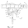
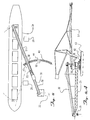
- FIGS. 1 and 1A where a loading system for transporting material to a desired location has been shown.
- the preferred embodiment of the system which will be referred to herein as a shiploader 20, has been illustrated while transporting material from an approach conveying means, which in a preferred embodiment is an approach conveyor 22 on to a ship 24.
- an approach conveying means which in a preferred embodiment is an approach conveyor 22 on to a ship 24.
- the instant invention may be equally useful in loading any other elongate transport device or area, such as a field on which heap leaching operations are to be carried out.
- the preferred embodiment shown and discussed herein is designed for transporting dry, fungible materials, it is also contemplated that the system discussed herein may be used to support pipelines that deliver slurries, such as concentrates, to a ship.
- the approach conveyor 22 may be used to deliver fungible materials 23, such as ores, grains, and the like, from a port and to a moorage area where the loading system is mounted.
- the approach conveyor 22 will carry the materials 23 from land and on to the shiploader 20.
- the materials 23 are transferred from the approach conveyor and on to the shiploader 20 through a discharge point 26 which may also include a chute or other means for controlling the delivery of the materials 23 to the shiploader 20.
- the loading system will be particularly well suited for delivering and distributing the material 23 to a set of cargo bins 28 on a ship 24 which has been moored against a fixed mooring structure 29, which includes tie-downs, as well as mooring and breasting dolphins with fenders.
- the ship will typically be secured, or docked, against the mooring structure 29.
- the mooring structure serves to maintain the ship at a predetermined longitudinal orientation relative to the shiploading system.
- the shiploading system will then begin to deliver the cargo materials 23 to the ship's cargo bins 28.
- a highly preferred embodiment of the shiploader 20 includes a bridge 30 which supports a bridge conveyor means 32 which includes a first end 34 and a second end 36.
- the first end 34 of the bridge conveyor 32 is pivotally positioned proximate to the discharge point 26 of the approach conveyor 22, so that material 23 being delivered by the approach conveyor 22 may be deposited on the first end 34 of the bridge conveyor 32.
- the bridge conveyor 32 is preferably a belt type conveyor, but it is contemplated that it may comprise a conveyor means such as a tube conveyor, pneumatic lift conveyor, or other known conveying means.
- the approach conveyor terminates at a discharge point 26, from which material 23 is transferred to the first end 34 of the bridge conveyor 32. Once the material 23 has been transferred on to the first end 34 of the bridge conveyor 32, it is then transported by the bridge conveyor 32 to the second end 36 of the bridge conveyor 32.
- the runway 40 includes a first end 42, a mid portion 44, and a second end 46.
- the first end 42 of the runway 40 is positioned near the mooring structure 29, so that the first end 42 of the runway 40 is closer to the ship 24 than the mid portion 44 of the runway.
- This arrangement for the runway allows the second end 36 of the bridge conveyor 32 to be moved along the runway 40 such that the second end 36 of the bridge conveyor 32 can be moved towards as well as away from the ship 24 which has been positioned next to the mooring structure 29.
- slewing boom 48 made from a stacker-like structure.
- stackers are proven effective for conveying materials such as the fungible materials which are typically transported by ship or train.
- stackers can use an open truss type structure, which employs a counterweight together with a vertical central mast or column that retains flexible suspension system made from tension members that extend to one or both ends of the boom.
- the structure of these booms may be very light in comparison to loading devices such as the linear loader when working at similar average loading rates.
- stackers have been typically used for delivering bulk materials to and from stockpiling areas on land.
- the instant invention allows use of stacker type mechanisms and structure for delivering bulk materials to the cargo bins 28.
- the slewing boom 48 is pivotally supported near the second end 36 of the bridge conveyor 32 on a slewing bearing 50 which is mounted over the carriage 38.
- the slewing boom 48 of the preferred embodiment includes a slewing boom 51 which includes a first end 52 and a second end 54.
- the first end 52 of the slewing boom 51 is positioned near the second end 36 of the bridge conveyor 32 in a manner that allows the bridge conveyor 32 to deliver and transfer material 23 to the first end of the slewing boom 51.
- the arrangement shown in FIGS. 1, 2, and 3 includes slewing booms 48, which include a counterweight 60.
- the use of the counterweight 60 allows the use of a balanced boom which, as explained earlier, is not simply cantilevered or held down on a moving support near the area at which the conveyor on the boom is loaded, as is done with the linear loader shown on FIGS. 1B and 1C or the quadrant loader shown on FIGS. 1D and 1E, or other systems that have to react traveling loads.
- By balancing the slewing boom by means of a counterweight one obviates the need for providing structure that reacts the loads imposed by the boom used to deliver the bulk materials to the cargo bins of the ship.
- an orbiting bridge and a slewing boom one may use lighter, open truss type, structure to support the conveyor belt on the slewing boom as well as on the orbiting bridge.
- the transfer of material 23 from the bridge conveyor 32 to the slewing boom 51 may carried out by simply depositing the material from the second end 36 of the bridge conveyor 32 through a chute 68.
- the slewing boom 51 of the preferred embodiment will also contain a conveying means 56, which in a preferred embodiment includes a belt type conveyor 58.
- the conveying means 56 includes a first end 59 and a second end 61. It should be noted that one of many well known material transfer mechanisms may be used in place of a belt conveyor.
- the conveying means 56 will transport material over the slewing boom 51 to the second end 54 of the slewing boom 51, where, in a preferred embodiment, a chute 57 accepts the material 23 from the conveying means 56 and directs its delivery into the ship's cargo bins 28.
- FIGS. 1, 2 and 3 reveals that by positioning of the runways 40 such that the closest point of the runway 40 is the first end 42, one provides a structure where the bridge will not be required to be aligned with the approach conveyor during its range of motion. In other words, the bridge will not have to be at a right angle to the moored vessel in order to load the vessel.
- FIGS. 4 and 5 where the second end 36 of the bridge conveyor 32 has been mounted on a frame 66 which supports the second end 36 of the bridge conveyor 32 on a slewing bearing 37.
- This is a variation from the embodiment illustrated in FIGS. 1, 2 and 3, which show the bridge conveyor 32 supported entirely by the truss structure of the bridge 30.
- a chute 68 At the second end 36 of the bridge conveyor 32 shown on FIGS. 1, 2, and 3 is a chute 68 which delivers the material 23 to the first end 52 of the slewing boom 51.
- the alternating chute 70 which has been mounted at the discharge point 26 of the approach conveyor 22.
- the alternating chute 70 includes a first delivery chute 72 and a second delivery chute 74. It is important to note that while the alternating chute 70 has been illustrated with the embodiment shown on FIG. 4, the delivery of material to the slewing boom may be accomplished by means of feeders or other distribution means that allow selective delivery to a desired orbiting bridge.
- the alternating chute 70 allows delivery of material through the first delivery chute 72, the second delivery chute 74, or both delivery chutes at a time. It is preferred that an alternating chute 70 be used in order to provide a system that allows alternating use of bridges 30 and cooperating slewing booms 51.
- the use of the alternating chute 70 increases the average loading rate of the system by allowing the loading of one cargo bin with one bridge and one slewing boom, while another bridge and slewing boom is moved to a desired cargo bin 28.
- one can achieve the continuous use of the system while loading a vessel, without requiring the stopping of the approach conveyor when shifting the cargo bin being loaded.
- another bridge and slewing boom could be shifted from one cargo bin to the next cargo bin to be loaded.
- the shiploader 20 as taught herein obviates the need to stop the approach conveyor 22 when shifting the loading from one cargo bin 28 to another.
- the loading of the vessel may be achieved in a safer manner with the instant invention.
- the increased safety is achieved due to the fact that the disclosed system allows simultaneous loading of cargo bins 28 near the bow of the ship while loading cargo bins near the stern of the ship. This results in a balanced loading of the ship, reducing the risk of problems such as bottoming out in shallow ports by placing too much load near stern of the vessel before the bow is loaded.
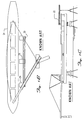
- FIGS. 6 and 6A From an examination of FIGS. 6 and 6A it will be understood that it is contemplated that the disclosed shiploader system taught herein may be used with an approach conveyor 22A is mounted on structure that functions like a finger pier application and which will be referred to herein as a finger structure 76.
- the ships 24A and 24B are positioned in a generally parallel fashion to the finger structure 76 and the approach conveyor 22.
- the installation shown on FIGS. 6 and 6A includes a pair of shiploaders 20A, each with a runway 40A, each of the runways 40A includes a first end 42A, a mid portion 44A, and a second end 46A. Note that the first end 42A of each of the runway 40A is the closer to the ship 24 than the mid portion 44A of the runway 40A. The second end 46A of each runway 40A is closer to the ship 24B than the mid portion 44A.
- the approach conveyor 22A is shown extending over one of the runways 40A.
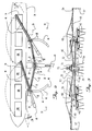
- FIGS. 7 and 7A A variation of an installation including the shiploading system taught herein is shown on FIGS. 7 and 7A.
- the installation shown on FIGS. 7 and 7A including a straight runway 78.
- the straight runway 78 including a first end 80, a mid portion 82, and a second end 84.
- the use of this embodiment would require that a sliding carriage and sliding head 90 be incorporated at the second end 36 of the bridge conveyor 32.
- the sliding carriage and sliding head 90 can slide relative to the bridge 30 as well as relative to the runway 78 in order to allow self adjustment compensating for the difference in distance from the discharge point 26 and the first end 80 of the runway 78 and the distance between the discharge point 26 and the mid portion 82 of the runway 78.
- FIG. 8 Shown on FIG. 8 is a contemplated installation of the shiploading system taught herein which includes a single bridge 30 and accompanying slewing boom 51 and runway 40 constructed as taught herein.
- the runway 40 and mooring structure 29 being positioned such that the first end of the runway 40 be closer to the ship 24 than the mid portion 44 of the runway 40 when a ship is positioned against the mooring structure 29.
- This embodiment is particularly useful for installations that are designed for loading small vessels. It should be noted that the use of an installation that incorporates a single orbiting bridge 30 combined with a single slewing boom 51 offers significant advantages that could not be achieved with known devices, in spite of the fact that this type of installation would not use a distributing chute.
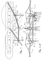
- FIGS. 9 and 9A are elevational views of the embodiment shown in FIG. 9.
- the central slewing boom 86 has been added to this embodiment to increase the longitudinal coverage of the system when used to load very large vessels.
- FIGS. 10 and 10A Yet another variation to the instant invention has been illustrated in FIGS. 10 and 10A, where the runway 40 extends under the approach conveyor 22.
- this embodiment would require that the structure supporting the approach conveyor be elevated as shown in FIG. 10A in order to allow the bridge and accompanying slewing boom to travel under the approach conveyor.
- the embodiment shown in FIGS. 10 and 10A is also shown with a central slewing boom 86A.
- FIGS. 10 and 10A would be used in installations where, due to favorable geographic conditions, the shiploading system could be mounted next to, and partially on, shore and on two short runways.
- the embodiment takes advantage of the favorable conditions, which would include deep water next to shore and a small runway, to incorporate a section of land based track 92 for the carriage 38.
- the track 92 would connect the two sections of runway 40 and allow the use of a single orbiting bridge 30 and a single slewing boom 51 to deliver cargo to a relatively large vessel. It is advantageous to use track over land or pier area since track is relatively inexpensive and easy to build.
- the method includes providing at least one bridge conveying means and a slewing means for conveying material from the bridge conveying means on to the slewing means.
- the process includes delivering material from the approach conveyor means on to the bridge conveying means, and then delivering the material from the bridge on to the slewing means.
- the process is then followed by the step of distributing the material over a ship's cargo bin by means of the slewing means.
Landscapes
- Chemical & Material Sciences (AREA)
- Engineering & Computer Science (AREA)
- Combustion & Propulsion (AREA)
- Mechanical Engineering (AREA)
- Ocean & Marine Engineering (AREA)
- Ship Loading And Unloading (AREA)
- Farming Of Fish And Shellfish (AREA)
- Flanged Joints, Insulating Joints, And Other Joints (AREA)
- Framework For Endless Conveyors (AREA)
Abstract
Description
Claims (7)
- A system (20) for transporting material from an approach conveying means (22) on to an elongate transport device (24), the elongate transport device (24) being positioned at a predetermined orientation relative to the approach conveying means (22), the system (20) comprising:characterized in that the slewing conveying means (48) is moveable from at least the runway's first end (42) to the runway's second end (46), the runway (40) terminating at the first end (42) of the runway (40), wherein in the predetermined orientation of the elongate transport device (24) relative to the approach conveying means (22),the mid-portion (82,44) of the runway (78,40) is normal (90°) or almost normal to, not parallel to, the elongate transport device (24), so that the second end (36) of the bridge conveying means (32) may move together with the first end (52) of the slewing conveying means (48), so that material from the approach conveying means (22) may be delivered to the first end (34) of the bridge conveying means (32) and then delivered by the bridge conveying means (32) to the second end (54) of the slewing conveying means (48), whereby the slewing conveying means (48) may deliver the material to the longitudinal transport device (24).at least one slewing conveying means (48) having a first end (52) and a second end (54), the slewing conveying means (48) pivoting and accepting material at the first end (52) and conveying the material to the second end (54), the second end (54) of the slewing conveying means (48) being capable of discharging the material on to the elongate transport device (24) ; anda bridge conveying means (32) having a first end (34) and a second end (36), the first end of the bridge conveying means (32) being pivotally supported for pivotal motion of the first end about a point near the approach conveying means (22) and the second end (36) of the bridge conveying means (32) being moveably supported near the first end of said slewing conveying means (48), the first end (52) of said slewing conveying means (48) is moveably mounted on a runway (78,40), the runway (78,40) having a first end (80,42), a second end (84,46) and a mid portion (82,44) between the first end (80,42) and the second end (84,46),
- A system according to Claim 1 wherein said runway (40) is arched.
- A system according to Claim 2 wherein said first end (52) of the slewing means (48) is mounted on carriage means (38) for moving the slewing means (48) over the runway (40).
- A system according to Claim 3 wherein said runway (40) is mounted at a distance from and independent of the approach conveying means (22).
- A system according to any one of the preceding claims wherein the first end (34) of the bridge conveyor means (32) is pivotally positioned proximate to the discharge point on the approach conveying means (22), and whereby material from the approach conveying means (22) may be delivered from the approach conveying means (22) onto the first end (34) of the bridge conveyor (32) and then delivered by the bridge conveyor (32) to the slewing conveying means (48), so that the material may then be delivered by the slewing conveying means (48) onto the elongate transport device (24) and adjustments of the position of the second end (54) of the slewing conveying means (48) may be made by moving the first end (52) of the slewing conveying means (48) over the runway (40).
- A ship loading system according to Claim 5 wherein said bridge conveyor means (32) comprises a pair of bridge conveyors.
- A method for producing a loaded shipment of material within a cargo bin of a ship (24), the ship (24) being moored at a predetermined position, the method comprising the steps of:characterized by the mid-portion (82,44) of the runway (78,40) being normal (90°) or almost normal to, not parallel to, the ship (24) when moored in the predetermined position, the flow of material being transferred from the approach conveying means (22) to the first end (34) of the bridge conveying means (32);providing a flow of material from an approach conveying means (22);transferring the flow of material from the approach conveying means (22) to a bridge conveying means (32) having a first end (34) and a second end (36), the first end (34) of the bridge conveying means (32) being pivotally supported for pivotal motion about a point near the approach conveying means (22) and the second end (36) of the bridge conveying means (32) being moveably supported on a runway (40), the runway (40) having a first end (42), a second end (46) and a mid portion (44) between the first end (42) and the second end (46), the runway terminating at the first end of the runway,
providing at least one slewing conveying means (48) having a first end (52) and a second end (54), the first end (52) of the slewing conveying means (48) being connected to and in fluid communication with the second end (36) of the bridge conveying means (32), the first end (52) of the slewing conveying means (48) pivoting and accepting the flow of material at the first end (52) of the slewing conveying means (48) and conveying the flow of material to the second end (54) of the slewing conveying means (48), the second end (54) of the slewing conveying means (48) being capable of discharging the flow of material in to the cargo bin of the ship (24) through a discharge point;
delivering the flow of material from the second end (36) of the bridge conveyor means (32) on to the first end (52) of the slewing conveying means (48), and
delivering the flow of material from the second end (54) of the slewing conveying means (48) into the cargo bin, so that the flow of material being delivered into the cargo bin may be continuously adjusted by simultaneously adjusting the position of the bridge conveyor means and the discharge point of the slewing conveyor means relative to the bridge conveyor means and the cargo bin.
Applications Claiming Priority (3)
| Application Number | Priority Date | Filing Date | Title |
|---|---|---|---|
| US854632 | 1997-05-12 | ||
| US08/854,632 US5871324A (en) | 1997-05-12 | 1997-05-12 | Shiploader system |
| PCT/US1998/009646 WO1998051564A1 (en) | 1997-05-12 | 1998-05-12 | Shiploader system |
Publications (3)
| Publication Number | Publication Date |
|---|---|
| EP0980328A1 EP0980328A1 (en) | 2000-02-23 |
| EP0980328A4 EP0980328A4 (en) | 2002-08-14 |
| EP0980328B1 true EP0980328B1 (en) | 2005-12-28 |
Family
ID=25319204
Family Applications (1)
| Application Number | Title | Priority Date | Filing Date |
|---|---|---|---|
| EP98921141A Expired - Lifetime EP0980328B1 (en) | 1997-05-12 | 1998-05-12 | Shiploader system |
Country Status (6)
| Country | Link |
|---|---|
| US (1) | US5871324A (en) |
| EP (1) | EP0980328B1 (en) |
| AT (1) | ATE314250T1 (en) |
| AU (1) | AU7381698A (en) |
| DE (1) | DE69832975D1 (en) |
| WO (1) | WO1998051564A1 (en) |
Cited By (1)
| Publication number | Priority date | Publication date | Assignee | Title |
|---|---|---|---|---|
| DE102019203301A1 (en) * | 2019-03-12 | 2020-09-17 | Thyssenkrupp Ag | Loading system for loading ships with bulk goods |
Families Citing this family (8)
| Publication number | Priority date | Publication date | Assignee | Title |
|---|---|---|---|---|
| US6132156A (en) * | 1998-04-15 | 2000-10-17 | Shehata; S. Ramsis | Ecological shiploader |
| WO2008079866A2 (en) * | 2006-12-21 | 2008-07-03 | Rail-Veyor Systems, Inc. | Method of controlling a rail transport system for conveying bulk materials |
| US7814855B2 (en) * | 2008-04-30 | 2010-10-19 | Tex-Mex Management, Llc | Swingable spacing dock |
| US8955667B1 (en) | 2011-08-09 | 2015-02-17 | Rail-Veyor Systems, Inc. | Bulk material handling system and method |
| US9776813B2 (en) * | 2013-06-21 | 2017-10-03 | Source Energy Services Canadian Logistics Lp | Mobile dry material storage |
| CN105236163B (en) * | 2015-11-16 | 2017-10-03 | 泰富重工制造有限公司 | A kind of material is bypassed the dam site or gap bridge movement system |
| CN109307154A (en) * | 2017-07-27 | 2019-02-05 | 中国船舶重工集团公司第七〇九研究所 | A kind of fluid delivery system for single point mooring unit |
| CN110642152B (en) * | 2019-10-16 | 2020-08-28 | 长沙理工大学 | A large-span bulk material conveying system |
Family Cites Families (16)
| Publication number | Priority date | Publication date | Assignee | Title |
|---|---|---|---|---|
| USRE26298E (en) * | 1967-11-21 | Method of and apparatus for transporting concrete | ||
| DE633616C (en) * | 1933-12-08 | 1936-07-31 | Franz Bock Fa | Ship loading system with an island on which the ships to be loaded can anchor |
| FR1037489A (en) * | 1951-05-25 | 1953-09-17 | Anciens Etablissements Noe L A | Pocket transporter frame with adjustable telescopic beam |
| US3361248A (en) * | 1966-10-24 | 1968-01-02 | Robert C. Daymon | Field conveyor |
| US3499522A (en) * | 1967-12-15 | 1970-03-10 | United States Steel Corp | Loading apparatus |
| ES391179A1 (en) * | 1970-06-24 | 1974-03-16 | Salzgitter A G | Arrangement for continuously transferring loads units |
| US3856159A (en) * | 1970-10-28 | 1974-12-24 | P Soros | Shipside cargo conveyance device |
| DE2516943C3 (en) * | 1975-04-17 | 1980-07-24 | Pohlig-Heckel-Bleichert Vereinigte Maschinenfabriken Ag, 5000 Koeln | Ship mooring |
| GB1536303A (en) * | 1976-08-17 | 1978-12-20 | Hoogovens Ijmuiden Bv | Ship loading system |
| DE2836469A1 (en) * | 1978-08-21 | 1980-03-06 | Weserhuette Ag Eisenwerk | Ship loading machine handling bulk material - has conveyor on boom adapted for slewing as well as derricking |
| GB2072132A (en) * | 1980-03-20 | 1981-09-30 | Howard Ltd C A E C | Bulk material handling conveyor system |
| SE426473B (en) * | 1980-07-01 | 1983-01-24 | Beltine Ab | CONTAINED WITH TRANSPORT BELTS Freight Unloading Device for Stacking or Loading of EX EX |
| CA1196881A (en) * | 1985-01-29 | 1985-11-19 | William H. Johnston | Bulk material reclaiming apparatus |
| US4925010A (en) * | 1986-06-11 | 1990-05-15 | Mannesmann Ag | Loading of pourable goods |
| NO167505C (en) * | 1989-01-30 | 1991-11-13 | Seatrans Ans | LOAD TRANSMISSION SYSTEM FOR SHIPPING AND UNLOADING. |
| US5193964A (en) * | 1991-07-08 | 1993-03-16 | Soros International | Slewing bridge material handling apparatus capable of continuous material feeding during moving and slewing |
-
1997
- 1997-05-12 US US08/854,632 patent/US5871324A/en not_active Expired - Lifetime
-
1998
- 1998-05-12 AU AU73816/98A patent/AU7381698A/en not_active Abandoned
- 1998-05-12 EP EP98921141A patent/EP0980328B1/en not_active Expired - Lifetime
- 1998-05-12 WO PCT/US1998/009646 patent/WO1998051564A1/en active IP Right Grant
- 1998-05-12 AT AT98921141T patent/ATE314250T1/en not_active IP Right Cessation
- 1998-05-12 DE DE69832975T patent/DE69832975D1/en not_active Expired - Lifetime
Cited By (2)
| Publication number | Priority date | Publication date | Assignee | Title |
|---|---|---|---|---|
| DE102019203301A1 (en) * | 2019-03-12 | 2020-09-17 | Thyssenkrupp Ag | Loading system for loading ships with bulk goods |
| WO2020182597A1 (en) | 2019-03-12 | 2020-09-17 | Thyssenkrupp Industrial Solutions Ag | Loading system for loading ships with bulk material |
Also Published As
| Publication number | Publication date |
|---|---|
| EP0980328A1 (en) | 2000-02-23 |
| EP0980328A4 (en) | 2002-08-14 |
| WO1998051564A1 (en) | 1998-11-19 |
| DE69832975D1 (en) | 2006-02-02 |
| US5871324A (en) | 1999-02-16 |
| AU7381698A (en) | 1998-12-08 |
| ATE314250T1 (en) | 2006-01-15 |
Similar Documents
| Publication | Publication Date | Title |
|---|---|---|
| US20120224946A1 (en) | Container Cargo Transfer System | |
| EP0980328B1 (en) | Shiploader system | |
| US3938676A (en) | Floating unloading installation for lighters | |
| US6390006B1 (en) | Sea bulk transfer vessel | |
| US20100028105A1 (en) | Floating Device for Transporting and Transferring Containers | |
| US20020071743A1 (en) | Container cargo transfer system | |
| US4483655A (en) | Vessel loading method | |
| CA1056324A (en) | Ship loading system | |
| KR101652695B1 (en) | Bulk shipment systems use transport barge | |
| AU2016363678A1 (en) | Super shallow draft bulk carrier | |
| CN204150732U (en) | A kind of multifunctional ship integrating shipment, unload a ship, transport | |
| US5049021A (en) | Self-unloading method and apparatus for ships | |
| RU2381167C2 (en) | Ship offshore loading and unloading device | |
| CN1057060C (en) | Cargo handling arrangements for ships not docking | |
| US6863484B2 (en) | Catamaran transfer vessel | |
| WO1982001859A1 (en) | Azimuthal mooring material handling terminal and tower | |
| US4065002A (en) | Pocket door ship loader | |
| SU1184773A1 (en) | Conveyer arrangement for reloading loose materials in ports | |
| CN103517868A (en) | Device and method for conveying packaged goods and/or bulk goods | |
| US6048153A (en) | System, apparatus and method for loading and/or unloading a barge | |
| CN212531528U (en) | Large water head lifting type ship loading mechanism | |
| US780083A (en) | Vessel for bunkering and loading ships. | |
| CN118289140A (en) | A large transfer barge mooring system and mooring method | |
| SU835914A1 (en) | Loose cargo transfer unit | |
| SU965922A1 (en) | Shore-based twin-cantilever grapple transloader |
Legal Events
| Date | Code | Title | Description |
|---|---|---|---|
| PUAI | Public reference made under article 153(3) epc to a published international application that has entered the european phase |
Free format text: ORIGINAL CODE: 0009012 |
|
| 17P | Request for examination filed |
Effective date: 19991213 |
|
| AK | Designated contracting states |
Kind code of ref document: A1 Designated state(s): AT BE CH CY DE DK ES FI FR GB GR IE IT LI LU MC NL PT SE |
|
| A4 | Supplementary search report drawn up and despatched |
Effective date: 20020627 |
|
| AK | Designated contracting states |
Kind code of ref document: A4 Designated state(s): AT BE CH CY DE DK ES FI FR GB GR IE IT LI LU MC NL PT SE |
|
| RIC1 | Information provided on ipc code assigned before grant |
Free format text: 7B 63B 27/10 A, 7B 65G 67/60 B, 7B 65G 63/04 B |
|
| 17Q | First examination report despatched |
Effective date: 20021115 |
|
| GRAP | Despatch of communication of intention to grant a patent |
Free format text: ORIGINAL CODE: EPIDOSNIGR1 |
|
| GRAS | Grant fee paid |
Free format text: ORIGINAL CODE: EPIDOSNIGR3 |
|
| GRAA | (expected) grant |
Free format text: ORIGINAL CODE: 0009210 |
|
| AK | Designated contracting states |
Kind code of ref document: B1 Designated state(s): AT BE CH CY DE DK ES FI FR GB GR IE IT LI LU MC NL PT SE |
|
| PG25 | Lapsed in a contracting state [announced via postgrant information from national office to epo] |
Ref country code: NL Free format text: LAPSE BECAUSE OF FAILURE TO SUBMIT A TRANSLATION OF THE DESCRIPTION OR TO PAY THE FEE WITHIN THE PRESCRIBED TIME-LIMIT Effective date: 20051228 Ref country code: LI Free format text: LAPSE BECAUSE OF FAILURE TO SUBMIT A TRANSLATION OF THE DESCRIPTION OR TO PAY THE FEE WITHIN THE PRESCRIBED TIME-LIMIT Effective date: 20051228 Ref country code: IT Free format text: LAPSE BECAUSE OF FAILURE TO SUBMIT A TRANSLATION OF THE DESCRIPTION OR TO PAY THE FEE WITHIN THE PRESCRIBED TIME-LIMIT;WARNING: LAPSES OF ITALIAN PATENTS WITH EFFECTIVE DATE BEFORE 2007 MAY HAVE OCCURRED AT ANY TIME BEFORE 2007. THE CORRECT EFFECTIVE DATE MAY BE DIFFERENT FROM THE ONE RECORDED. Effective date: 20051228 Ref country code: FI Free format text: LAPSE BECAUSE OF FAILURE TO SUBMIT A TRANSLATION OF THE DESCRIPTION OR TO PAY THE FEE WITHIN THE PRESCRIBED TIME-LIMIT Effective date: 20051228 Ref country code: CH Free format text: LAPSE BECAUSE OF FAILURE TO SUBMIT A TRANSLATION OF THE DESCRIPTION OR TO PAY THE FEE WITHIN THE PRESCRIBED TIME-LIMIT Effective date: 20051228 Ref country code: BE Free format text: LAPSE BECAUSE OF FAILURE TO SUBMIT A TRANSLATION OF THE DESCRIPTION OR TO PAY THE FEE WITHIN THE PRESCRIBED TIME-LIMIT Effective date: 20051228 Ref country code: AT Free format text: LAPSE BECAUSE OF FAILURE TO SUBMIT A TRANSLATION OF THE DESCRIPTION OR TO PAY THE FEE WITHIN THE PRESCRIBED TIME-LIMIT Effective date: 20051228 |
|
| REG | Reference to a national code |
Ref country code: GB Ref legal event code: FG4D |
|
| REG | Reference to a national code |
Ref country code: CH Ref legal event code: EP |
|
| REG | Reference to a national code |
Ref country code: IE Ref legal event code: FG4D |
|
| REF | Corresponds to: |
Ref document number: 69832975 Country of ref document: DE Date of ref document: 20060202 Kind code of ref document: P |
|
| PG25 | Lapsed in a contracting state [announced via postgrant information from national office to epo] |
Ref country code: SE Free format text: LAPSE BECAUSE OF FAILURE TO SUBMIT A TRANSLATION OF THE DESCRIPTION OR TO PAY THE FEE WITHIN THE PRESCRIBED TIME-LIMIT Effective date: 20060328 Ref country code: GR Free format text: LAPSE BECAUSE OF FAILURE TO SUBMIT A TRANSLATION OF THE DESCRIPTION OR TO PAY THE FEE WITHIN THE PRESCRIBED TIME-LIMIT Effective date: 20060328 Ref country code: DK Free format text: LAPSE BECAUSE OF FAILURE TO SUBMIT A TRANSLATION OF THE DESCRIPTION OR TO PAY THE FEE WITHIN THE PRESCRIBED TIME-LIMIT Effective date: 20060328 |
|
| PG25 | Lapsed in a contracting state [announced via postgrant information from national office to epo] |
Ref country code: DE Free format text: LAPSE BECAUSE OF FAILURE TO SUBMIT A TRANSLATION OF THE DESCRIPTION OR TO PAY THE FEE WITHIN THE PRESCRIBED TIME-LIMIT Effective date: 20060329 |
|
| PG25 | Lapsed in a contracting state [announced via postgrant information from national office to epo] |
Ref country code: ES Free format text: LAPSE BECAUSE OF FAILURE TO SUBMIT A TRANSLATION OF THE DESCRIPTION OR TO PAY THE FEE WITHIN THE PRESCRIBED TIME-LIMIT Effective date: 20060408 |
|
| PG25 | Lapsed in a contracting state [announced via postgrant information from national office to epo] |
Ref country code: IE Free format text: LAPSE BECAUSE OF NON-PAYMENT OF DUE FEES Effective date: 20060512 |
|
| PG25 | Lapsed in a contracting state [announced via postgrant information from national office to epo] |
Ref country code: PT Free format text: LAPSE BECAUSE OF FAILURE TO SUBMIT A TRANSLATION OF THE DESCRIPTION OR TO PAY THE FEE WITHIN THE PRESCRIBED TIME-LIMIT Effective date: 20060529 |
|
| PG25 | Lapsed in a contracting state [announced via postgrant information from national office to epo] |
Ref country code: MC Free format text: LAPSE BECAUSE OF NON-PAYMENT OF DUE FEES Effective date: 20060531 |
|
| NLV1 | Nl: lapsed or annulled due to failure to fulfill the requirements of art. 29p and 29m of the patents act | ||
| REG | Reference to a national code |
Ref country code: CH Ref legal event code: PL |
|
| PLBE | No opposition filed within time limit |
Free format text: ORIGINAL CODE: 0009261 |
|
| STAA | Information on the status of an ep patent application or granted ep patent |
Free format text: STATUS: NO OPPOSITION FILED WITHIN TIME LIMIT |
|
| 26N | No opposition filed |
Effective date: 20060929 |
|
| REG | Reference to a national code |
Ref country code: IE Ref legal event code: MM4A |
|
| PG25 | Lapsed in a contracting state [announced via postgrant information from national office to epo] |
Ref country code: FR Free format text: LAPSE BECAUSE OF FAILURE TO SUBMIT A TRANSLATION OF THE DESCRIPTION OR TO PAY THE FEE WITHIN THE PRESCRIBED TIME-LIMIT Effective date: 20070216 |
|
| PG25 | Lapsed in a contracting state [announced via postgrant information from national office to epo] |
Ref country code: LU Free format text: LAPSE BECAUSE OF NON-PAYMENT OF DUE FEES Effective date: 20060512 |
|
| PG25 | Lapsed in a contracting state [announced via postgrant information from national office to epo] |
Ref country code: FR Free format text: LAPSE BECAUSE OF FAILURE TO SUBMIT A TRANSLATION OF THE DESCRIPTION OR TO PAY THE FEE WITHIN THE PRESCRIBED TIME-LIMIT Effective date: 20051228 Ref country code: CY Free format text: LAPSE BECAUSE OF FAILURE TO SUBMIT A TRANSLATION OF THE DESCRIPTION OR TO PAY THE FEE WITHIN THE PRESCRIBED TIME-LIMIT Effective date: 20051228 |
|
| PGFP | Annual fee paid to national office [announced via postgrant information from national office to epo] |
Ref country code: GB Payment date: 20090625 Year of fee payment: 12 |
|
| GBPC | Gb: european patent ceased through non-payment of renewal fee |
Effective date: 20100512 |
|
| PG25 | Lapsed in a contracting state [announced via postgrant information from national office to epo] |
Ref country code: GB Free format text: LAPSE BECAUSE OF NON-PAYMENT OF DUE FEES Effective date: 20100512 |