CN110642152B - Large-span bulk cargo conveying system - Google Patents
Large-span bulk cargo conveying system Download PDFInfo
- Publication number
- CN110642152B CN110642152B CN201910984451.6A CN201910984451A CN110642152B CN 110642152 B CN110642152 B CN 110642152B CN 201910984451 A CN201910984451 A CN 201910984451A CN 110642152 B CN110642152 B CN 110642152B
- Authority
- CN
- China
- Prior art keywords
- arm
- conveying
- conveyor
- conveying arm
- balance
- Prior art date
- Legal status (The legal status is an assumption and is not a legal conclusion. Google has not performed a legal analysis and makes no representation as to the accuracy of the status listed.)
- Active
Links
Images


Classifications
-
- B—PERFORMING OPERATIONS; TRANSPORTING
- B66—HOISTING; LIFTING; HAULING
- B66C—CRANES; LOAD-ENGAGING ELEMENTS OR DEVICES FOR CRANES, CAPSTANS, WINCHES, OR TACKLES
- B66C23/00—Cranes comprising essentially a beam, boom, or triangular structure acting as a cantilever and mounted for translatory of swinging movements in vertical or horizontal planes or a combination of such movements, e.g. jib-cranes, derricks, tower cranes
- B66C23/62—Constructional features or details
- B66C23/72—Counterweights or supports for balancing lifting couples
-
- B—PERFORMING OPERATIONS; TRANSPORTING
- B65—CONVEYING; PACKING; STORING; HANDLING THIN OR FILAMENTARY MATERIAL
- B65G—TRANSPORT OR STORAGE DEVICES, e.g. CONVEYORS FOR LOADING OR TIPPING, SHOP CONVEYOR SYSTEMS OR PNEUMATIC TUBE CONVEYORS
- B65G15/00—Conveyors having endless load-conveying surfaces, i.e. belts and like continuous members, to which tractive effort is transmitted by means other than endless driving elements of similar configuration
- B65G15/22—Conveyors having endless load-conveying surfaces, i.e. belts and like continuous members, to which tractive effort is transmitted by means other than endless driving elements of similar configuration comprising a series of co-operating units
- B65G15/26—Conveyors having endless load-conveying surfaces, i.e. belts and like continuous members, to which tractive effort is transmitted by means other than endless driving elements of similar configuration comprising a series of co-operating units extensible, e.g. telescopic
-
- B—PERFORMING OPERATIONS; TRANSPORTING
- B65—CONVEYING; PACKING; STORING; HANDLING THIN OR FILAMENTARY MATERIAL
- B65G—TRANSPORT OR STORAGE DEVICES, e.g. CONVEYORS FOR LOADING OR TIPPING, SHOP CONVEYOR SYSTEMS OR PNEUMATIC TUBE CONVEYORS
- B65G63/00—Transferring or trans-shipping at storage areas, railway yards or harbours or in opening mining cuts; Marshalling yard installations
- B65G63/02—Transferring or trans-shipping at storage areas, railway yards or harbours or in opening mining cuts; Marshalling yard installations with essentially horizontal transit otherwise than by bridge
- B65G63/027—Transferring or trans-shipping at storage areas, railway yards or harbours or in opening mining cuts; Marshalling yard installations with essentially horizontal transit otherwise than by bridge for bulk material
-
- B—PERFORMING OPERATIONS; TRANSPORTING
- B65—CONVEYING; PACKING; STORING; HANDLING THIN OR FILAMENTARY MATERIAL
- B65G—TRANSPORT OR STORAGE DEVICES, e.g. CONVEYORS FOR LOADING OR TIPPING, SHOP CONVEYOR SYSTEMS OR PNEUMATIC TUBE CONVEYORS
- B65G65/00—Loading or unloading
- B65G65/28—Piling or unpiling loose materials in bulk, e.g. coal, manure, timber, not otherwise provided for
-
- B—PERFORMING OPERATIONS; TRANSPORTING
- B66—HOISTING; LIFTING; HAULING
- B66C—CRANES; LOAD-ENGAGING ELEMENTS OR DEVICES FOR CRANES, CAPSTANS, WINCHES, OR TACKLES
- B66C17/00—Overhead travelling cranes comprising one or more substantially horizontal girders the ends of which are directly supported by wheels or rollers running on tracks carried by spaced supports
-
- B—PERFORMING OPERATIONS; TRANSPORTING
- B66—HOISTING; LIFTING; HAULING
- B66C—CRANES; LOAD-ENGAGING ELEMENTS OR DEVICES FOR CRANES, CAPSTANS, WINCHES, OR TACKLES
- B66C23/00—Cranes comprising essentially a beam, boom, or triangular structure acting as a cantilever and mounted for translatory of swinging movements in vertical or horizontal planes or a combination of such movements, e.g. jib-cranes, derricks, tower cranes
- B66C23/62—Constructional features or details
- B66C23/64—Jibs
- B66C23/68—Jibs foldable or otherwise adjustable in configuration
-
- B—PERFORMING OPERATIONS; TRANSPORTING
- B66—HOISTING; LIFTING; HAULING
- B66C—CRANES; LOAD-ENGAGING ELEMENTS OR DEVICES FOR CRANES, CAPSTANS, WINCHES, OR TACKLES
- B66C23/00—Cranes comprising essentially a beam, boom, or triangular structure acting as a cantilever and mounted for translatory of swinging movements in vertical or horizontal planes or a combination of such movements, e.g. jib-cranes, derricks, tower cranes
- B66C23/62—Constructional features or details
- B66C23/84—Slewing gear
-
- B—PERFORMING OPERATIONS; TRANSPORTING
- B65—CONVEYING; PACKING; STORING; HANDLING THIN OR FILAMENTARY MATERIAL
- B65G—TRANSPORT OR STORAGE DEVICES, e.g. CONVEYORS FOR LOADING OR TIPPING, SHOP CONVEYOR SYSTEMS OR PNEUMATIC TUBE CONVEYORS
- B65G2201/00—Indexing codes relating to handling devices, e.g. conveyors, characterised by the type of product or load being conveyed or handled
- B65G2201/04—Bulk
Abstract
The invention discloses a large-span bulk cargo conveying system. Comprises a folding arm conveyor and a cross-dike lifting type feeding conveying device. The folding arm conveyor mainly comprises an underframe arranged on the ground of a stock yard, a tower body arranged on the underframe, a balance arm, a conveying arm, a tower top and other main parts, wherein the balance arm, the conveying arm and the tower top are arranged on the tower body. The gantry frame I, the gantry frame II and the unloading trolley are arranged on the conveying arm, the rotating device and the hopper are arranged on the tower body, and the balance trolley is arranged on the balance arm. The folding arm conveyor can realize horizontal rotation and can fold and withdraw the conveying arm through the winch control wire rope, can prevent to rotate in-process and collide with other equipment or building, also can effectively reduce the risk that the conveyer takes place to topple over under the wind-force effect. The invention has the characteristics of simple structure, low cost, ground space saving, automatic control and the like.
Description
Technical Field
The invention relates to a large-span bulk cargo conveying system, and belongs to the field of conveyors.
Background
At present, along with the rapid development of economic society, the demand for the grit is also bigger and bigger, how to carry out all-round transportation and stack to the grit is the problem that awaits a urgent solution. The prior art adopts the sand carrier, transports the sand to the river levee through the sand carrier, transports the gravel to the stockyard through the transportation equipment beside the river levee, and piles the material. In large stockyard, belt conveyor is the preferred conveying equipment. The conveyor can only convey the gravel to the position along the conveyor belt, so that the problems of insufficient site utilization rate, low working efficiency of the conveyor and the like still exist in the existing large stockyard. The traditional solution is to use other equipment to transport the gravel again, so the cost and the management difficulty are inevitably increased.
During the use of the conveyor, the following problems actually exist:
1. the prior art has a folding conveying arm to realize the functions of long-distance conveying and storage, however, the folding arm is generally two-section folding, and three-section folding is basically assisted by various devices such as hydraulic cylinders, and the like, but the hydraulic cylinders cannot realize complete unfolding, and an auxiliary structure is also needed.
2. The conveyer of prior art, the counter weight form is single, can not realize multistage variable counter weight. Especially large-scale equipment, it is more difficult to realize multi-stage variable counterweights.
3. The stroke control in the prior art is usually only a limiting element such as a bump, an anti-collision block and the like, but the limiting element has a single structure and cannot realize dynamic stroke control. Particularly, in the conveyor, the folding and unfolding states of the folding arm are that large equipment moves, and the dynamic stroke control of the folding arm is particularly important, and the problem is not solved in the prior art.
4. The conveyer belt, the hopper of prior art carry the back that finishes, have some to remain, are unsuitable to start entire system again this moment, and prior art does not have nimble solution.
5. The upstream conveyor and the downstream conveyor in the prior art lack stable connection relationship and functional connection relationship, which wastes resources and efficiency.
6. Taking the Changsha Xiangjiang river section as an example, the maximum water level can reach 39.21m in the flood season of 4-9 months per year, the dry water period of 10 months-3 months next year, and the minimum water level is as low as 25.15 m. At present, sand unloading ships in sand plants can unload sand normally in the season of rich water but can not unload sand in the season of dry water, so a cross-dike lifting type feeding device needs to be designed to convey sand to a stockyard.
7. The hoppers of the prior art generally adopt large-area brackets, that is, the brackets are often integral panels, so that the brackets have enough strength to support the valve plate below the hopper; occasionally, there are foot-type brackets that hold the valve plate to the feet, but this plate has a large area, adding much weight and range of motion.
8. Between the overlapping guide rails of the prior art, the problem of stress of the guide rail below is a great problem, especially in the embankment-crossing lifting type feeding conveying equipment, the first telescopic conveyor is located on the second telescopic conveyor, the problem of stress of the second telescopic conveyor is troubled all the time, and generally, the larger volume and the solid design are adopted for insurance.
9. The structure of a cable-stayed moving device in the prior art, such as a lifting feeding trolley in a cross-bank lifting type feeding conveying device, is often solid, and the consumed materials are large.
Disclosure of Invention
In order to overcome the problems, the invention aims to provide a scheme of a horizontal rotating folding arm conveyor.
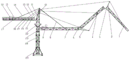
The invention solves the technical problem by adopting the technical scheme that the large-span bulk material conveying system comprises a folding arm conveyor and a cross-dike lifting type conveying device, wherein the folding arm conveyor comprises three sections of conveying arms, a tower top (10), a balance arm (17), a tower body (24), an underframe (25), a winch, a steel wire rope, a portal frame and a limiting device; the underframe (25) is fixedly installed in the stockyard through foundation bolts, and the tower body (24) is also connected with the underframe (25) through bolts;
the three sections of conveying arms are respectively a first conveying arm (7), a second conveying arm (4) and a third conveying arm (1), wherein the first conveying arm (7) is installed on the tower body (24) through a pin shaft, the second conveying arm (4) is connected to the first conveying arm (7) through a pin shaft, the third conveying arm (1) is connected to the second conveying arm through a pin shaft, the third conveying arm (1) is of a trapezoidal structure, and a discharging trolley (9) is arranged on the conveying arm; the gantry I (5) is arranged at one end (4) of the first conveying arm (7) close to the second conveying arm, and the limiting device I (6) is also arranged on the first conveying arm; the portal frame II (2) is arranged at one end, close to the second conveying arm (4), of the third conveying arm (1), and the limiting device II (3) is also arranged on the third conveying arm;
the balance arm (17) is arranged on the tower body (24) through a pin shaft; the tower top (10) is connected to the tower body (24) through a bolt; the winch comprises a winch I (21), a winch II (20), a winch III (19) and a winch IV (18), and the winches are sequentially arranged on the balance arm (17);
a steel wire rope I (11) controlled by a winch I (21) sequentially bypasses a pulley block at the top end of the tower top, a pulley block at the top end of a portal frame I (5) and a pulley block at the lower part of a second conveying arm (4); a steel wire rope II (12) controlled by the winch II (20) bypasses a pulley block arranged on the tower top (10) and finally bypasses the pulley block positioned at the upper part of the second conveying arm (4); a steel wire rope III (13) controlled by a winch III (19) sequentially bypasses a pulley block positioned at the top of the tower (10), a pulley block at the top end of a portal frame II (2) and a pulley block at the side part of the third conveying arm (1); a rotating device (23) and a hopper (22) are arranged on the tower body (24);
the distance between the position of the pulley block at the lower part of the second conveying arm and the two ends of the second conveying arm is a first distance and a second distance respectively, and the first distance is twice as long as the second distance; the distance between the position of the pulley block at the side part of the third conveying arm and the two ends of the third conveying arm is respectively a third distance and a fourth distance, the third distance is twice as long as the fourth distance, and the pulley block at the upper part of the second conveying arm and the pulley block at the lower part of the second conveying arm are arranged side by side;
the cross-bank lifting type conveying equipment comprises: the device comprises a track system (101), a lifting feeding trolley (102), a feeding hopper system (103), a telescopic conveyor (104), a winch (105), a variable amplitude conveyor (107) and a fixed conveyor (109), wherein the guide rail system (101) comprises a buffer spring (101.1) and a guide rail (101.2), and the buffer spring (101.1) is positioned under the guide rail (101.2);
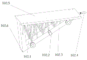
the lifting feeding trolley (102) comprises a support rod (102.1), a clamp type brake (102.2), a lower base plate (102.3), a lifting hook (102.4), an upper support plate (102.5) and a water level sensor (102.6), wherein the clamp type brake (102.3) is arranged on two sides of the lifting feeding trolley (102), and the lifting hook (102.4) is arranged in front of the lifting feeding trolley (102);
the feeding hopper system (3) comprises a feeding hopper (103.1), a hopper door (103.2), a vibrating rod (103.3), suspension rods (103.4), ribs (103.5), flat rods (103.6), valve rails (103.7), a valve plate (103.8), support legs (103.9) and inclined rods (103.10), wherein the vibrating rod (103.3) is installed inside the feeding hopper (103.1), an opening is formed below the feeding hopper, the valve plate can move to open and close the opening, four support legs are arranged at four corners of the feeding hopper, the inner sides of the support legs are connected with the ribs, the four ribs extend upwards, the extending tail ends are connected with the flat rods, the four flat rods form a square and are connected to the bottom surface of the feeding hopper, three suspension rods are connected below one flat rod, the lower ends of the three suspension rods are connected with the valve rails, the valve plate is installed on the valve rails, and can move along the valve rails to open and close; two inclined rods are connected between two support legs at one side of the suspension rod to enhance the support of the suspension rod and the valve plate, and the inclined rods are not arranged at the other three sides; the four support legs are connected at the four corners of the upper support plate (102.5).
Preferably, the balance arm (17) and the conveying arm are respectively installed on two sides of the tower body (24), the installation position of the balance arm (17) is higher than that of the conveying arm, and the balance arm (17) and the conveying arm are respectively connected with a cross beam located at the top end of the tower top through a balance arm pull rod (14) and a conveying arm pull rod (8).
Preferably, one end of the first conveying arm (7) close to the tower body (23) is provided with a driving roller, and the tail end of the third conveying arm (1) is provided with a driven roller; the first conveying arm (7), the second conveying arm (4) and the third conveying arm (1) are respectively provided with a groove-shaped carrier roller group, a return idler and a pinch roller, the pinch roller is used for preventing the conveying belt from being separated from the carrier roller in the folding and unfolding processes of the conveying arms, and the discharging trolley (9) can move along the conveying arms.
Preferably, three groups of pulley blocks are sequentially arranged on the tower top (10) from bottom to top and are respectively used for bypassing the steel wire rope I (11), the steel wire rope II (12) and the steel wire rope III (13).
Preferably, a rotating device (23) is arranged on the tower body (24), and the rotating device can drive the conveying arm and the balance arm (17) to rotate in the horizontal plane; the hopper (22) is tiltable relative to the tower for cleaning; the movement of the turning device (23) and the discharge trolley (9) is controlled by a programmable control system.
Preferably, the first distance is a distance between a position of the pulley block at the lower part of the second conveying arm and one end of the second conveying arm close to the tower body in the unfolded state.
Preferably, a balance trolley (16) and a travel switch are arranged on the balance arm (17); the balance trolley is connected with a winch IV through a steel wire rope IV, and the movement of the balance trolley is controlled by the winch IV (18) based on PLC programming automatic control; when the conveying arm is in a folded state, an unfolded no-load state, an unfolded middle-load state and an unfolded heavy-load state, the balance trolleys respectively run to four corresponding positions on the balance arm, and the trolleys run to different positions so as to balance overturning moments brought by the conveying arm in different states; a travel switch is respectively arranged on each position, and the positions from near to far away from the tower body are respectively named as a travel switch I, a travel switch II, a travel switch III and a travel switch IV; the lower end of the balance arm (17) is provided with a clamping hook which is used for being connected with the fixed conveyor (109) and taking the weight of the fixed conveyor (109) as a balance weight.
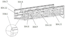
Preferably, the telescopic conveyor (104) comprises a first telescopic conveyor (104.1) and a second telescopic conveyor (104.5), the first telescopic conveyor (104.1) is positioned above the second telescopic conveyor (104.5), the first telescopic conveyor (104.1) is connected to the center of the upper support plate (102.5) through a boom connecting piece (102.7), and one end of the first telescopic conveyor (104.1) is provided with an angle sensor (104.4) and a material baffle plate (104.7); the swing angle of the second telescopic conveyor (104.5) is driven by the leveling cylinder (106.1); the telescopic arm support is characterized in that arm support small wheels (104.3) are arranged below the first telescopic conveyor (104.1), guide rails (104.6) are arranged above the second telescopic conveyor (104.5), the arm support small wheels move on the guide rails, the guide rails of the second telescopic conveyor (104.5) are supported by vertical beams (104.10), an inclined beam (104.9) is connected between the two vertical beams, a support beam (104.8) is arranged between planes where the two guide rails are located, an upper cross beam (104.12) is arranged below the two guide rails, a lower cross beam (104.11) is arranged below the upper cross beam, two support beams are respectively arranged on the left side and the right side of the crossing position of the inclined beam and the upper cross beam, and a support beam is arranged at the crossing position of the vertical beam and the lower cross beam.
Preferably, the winch (105) is connected with the lifting hook (102.4) through a pulley block; the pitching angle of the variable-amplitude conveyor (107) is changed through a hydraulic oil cylinder (106.2); the fixed conveyor (109) is connected with the amplitude variable conveyor (107) through a connecting piece (108); support post (110) are installed to fixed conveyer (109) below, the peg is installed to fixed conveyer (109) end, peg (119) can for fixed conveyer (109) carry out 90 degrees rotations, but the peg overlap joint is fixed the trip.
Compared with the prior art, the invention has the beneficial effects that:
1. aiming at the problem of the 1 st point in the background technology, on the basis that the three-section conveying arm is provided with the steel wire rope, a multi-point positive and negative traction scheme is adopted, three-section folding is realized only through the steel wire rope, the multi-point positive and negative traction comprises a point on a portal frame, a point on a pulley block at the lower part, a point on a pulley block at the upper part, a point on a pulley block at the side part and the like, the multi-point traction realizes three-section folding and unfolding through forward pulling and backward pulling, the use of a hydraulic cylinder and a complex matching structure is avoided, and the cost is greatly saved.
2. Aiming at the problem of the 2 nd point in the background art, the design of a movable balance car is adopted, different force arms and moments are obtained through the balance car at different points, and dynamic balance weight is realized.
3. Aiming at the 3 rd point of the background technology, the dynamic limiting of the portal frame is realized through the combined action of the supporting block and the sliding block, so that the dynamic supporting and limiting effects are realized on the steel wire rope and the conveying arm connected with the portal frame.
4. Aiming at the 4 th point of the background technology, when the materials are residual, the materials in the hopper are received by the inclined plate on the discharging trolley, and the residual materials are obtained.
5. Aiming at the 5 th point of the background technology, the design of the double-acting hanging rod is adopted, the double-acting hanging rod can be used as a horizontal connecting piece and a horizontal overlapping piece of equipment between an upstream position and a downstream position, and can also be connected with a rotary conveying device above through 90-degree rotation, so that the whole cross-dike lifting type feeding conveying equipment is used as a balance weight. The lower end of the balance arm is provided with a clamping hook which is used for being connected with upstream equipment and is used as a balance weight by virtue of the weight of the upstream equipment.
6. Aiming at the 6 th point of the background technology, the lifting feeding trolley is adopted to move up and down through the slope of the river bank, and then four steps of overlapping telescopic rail conveying, variable amplitude conveying and fixed conveying are adopted to solve the different water level working conditions of low water and rich water, so that the device is suitable for long-distance and short-distance conveying, and has wider adaptability and longer conveying distance.
7. Aiming at the 7 th point of the background technology, the reinforcing ribs are arranged on the supporting legs, the square hoops (flat rods) arranged above the reinforcing ribs are used as suspension pieces, the structural strength of the valve plate assembly is guaranteed, meanwhile, the unilateral suspension structure is arranged below the hopper, so that the conveying distance of the valve plate is not large, and meanwhile, the area of the valve plate is not enlarged for the reason of fixed connection.
8. Aiming at the 8 th point of the background technology, the stress structure of the second telescopic conveyor is refined, and materials are saved to the maximum extent on the basis of ensuring the strength through arrangement among the supporting beam, the oblique beam and the vertical beam.
9. Aiming at the 9 th point of the background technology, the combined supporting rod is arranged between the upper supporting plate and the lower bottom plate, so that the supporting strength is ensured to the maximum extent, and the material is saved.
Drawings
Fig. 1 is a schematic view of a transport arm in a folded state.
Fig. 2 is a schematic diagram of the gantry i pulling up the second conveying arm and the third conveying arm to a vertical state.
Fig. 3 is a schematic view showing the second and third transfer arms deployed under gravity and tension of a wire rope.
Fig. 4 is a schematic view of the transport arm fully deployed.
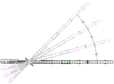
Fig. 5 is a schematic view of the conveyor rotating in a horizontal plane.
Fig. 6 is a schematic diagram of the limiting device for limiting the position of the portal frame.
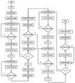
Fig. 7 is a flowchart of a procedure for automatically controlling the conveyor in the stockyard.
Fig. 8 is a schematic view of the invention in a cross-bank delivery stacking system, the invention being located at the end of the stacking system.
Fig. 9 is a schematic view of the overall structure of the embankment-crossing elevating type conveying equipment.
Fig. 10 is a schematic view of the overall structure of the feed trolley.
Fig. 11 is a schematic view of a feed hopper of the present invention.
Fig. 12 is a schematic view of a first telescopic conveyor of the present invention.
Fig. 13 is a schematic view of a second telescopic conveyor of the present invention.
Fig. 14 is a schematic view of a telescopic conveyor link of the present invention.
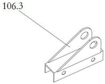
Figure 15 is a schematic view of a hydraulic ram mount 6.3 of the present invention.
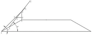
Fig. 16 is a schematic diagram for deriving the stroke function of the leveling cylinder 6.1 of the invention.
Description of reference numerals: 1-third conveying arm, 2-portal frame II, 3-limiting device II, 4-second conveying arm, 5-portal frame I, 6-limiting device I, 7-first conveying arm, 8-conveying arm pull rod, 9-discharge trolley, 10-tower top, 11 steel wire rope I, 12-steel wire rope II, 13 steel wire rope III, 14-balance arm pull rod, 15-steel wire rope IV, 16-balance trolley, 17-balance arm, 18-winch IV, 19-winch III, 20-winch II, 21-winch I, 22-hopper, 23-slewing device, 24-tower body, 25-underframe, 26-sand unloading boat, 27-lifting feeding device, 28-breakwater amplitude device, 29-horizontal rotating central folding arm conveyor, 30-stock yard, 31-river dike, 32-partition board, 33-lower cavity, 34-supporting block, 35-slide block, 36-frame, 37-upper chamber, 101-rail system, 101.1-buffer spring, 101.2-guide rail, 102-lifting feeding trolley, 102.1-support rod, 102.2-clamp brake, 102.3-lower bottom plate, 102.4-hook, 102.5-upper support plate, 102.6-water level sensor, 103-feed hopper system, 103.1-feed hopper, 103.2-hopper door, 103.3-vibrating rod, 103.4-suspension rod, 103.5-rib, 103.6-flat rod, 103.7-valve rail, 103.8-valve plate, 103.9-support leg, 103.10-diagonal rod, 104-telescopic conveyor, 104.1-first telescopic conveyor, 104.2-arm support small wheel support frame, 104.3-arm support small wheel, 104.4-angle sensor, 104.5-second telescopic conveyor, 104.6-guide rail, 104.7 parts of a striker plate, 104.8 parts of a support beam, 104.9 parts of an oblique beam, 104.10 parts of a vertical beam, 104.11 parts of a lower beam, 104.12 parts of an upper beam, 105 parts of a winch, 106 parts of a hydraulic oil cylinder system, 106.1 parts of a leveling oil cylinder, 106.2 parts of a hydraulic oil cylinder, 106.3 parts of a hydraulic oil cylinder support, 107 parts of a variable-amplitude conveyor, 107.1 parts of a distance sensor, 108 parts of a connecting plate, 109 parts of a fixed conveyor, 110 parts of an upright post, 111 parts of a slope, 112 parts of a support and 119 parts of a hanging rod.
Detailed Description
The invention is further explained below with reference to the drawings and examples.
As shown in the figure: a large-span bulk material conveying system comprises a folding arm conveyor and a cross-dike lifting type feeding conveying device. The folding arm conveyor comprises three-section conveying arms, a tower top 10, a balance arm 17, a tower body 24 and an underframe 25. The device also comprises a winch, a steel wire rope, a portal frame and a limiting device; the underframe 25 is fixedly installed in the stockyard through foundation bolts, and the tower body 24 is also connected with the underframe 25 through bolts; the three sections of conveying arms are respectively a first conveying arm 7, a second conveying arm 4 and a third conveying arm 1, wherein the first conveying arm 7 is installed on the tower body 24 through a pin shaft, the second conveying arm 4 is connected to the first conveying arm 7 through a pin shaft, the third conveying arm 1 is connected to the second conveying arm 4 through a pin shaft, the third conveying arm 1 is of a trapezoidal structure, and a discharging trolley 9 is arranged on the conveying arm; the gantry I5 is arranged at one end 4, close to the second conveying arm, of the first conveying arm 7, and the limiting device I6 is also arranged on the first conveying arm; the portal frame II 2 is arranged at one end, close to the second conveying arm 4, of the third conveying arm 1, and the limiting device II 3 is also arranged on the third conveying arm; the balance arm 17 is arranged on the tower body 24 through a pin shaft; the tower top 10 is connected to the tower body 24 through bolts; the winch comprises a winch I21, a winch II 20, a winch III 19 and a winch IV 18 which are sequentially arranged on the balance arm 17, and a steel wire rope I11 controlled by the winch I21 sequentially bypasses a tower top end pulley block, a portal frame I5 top end pulley block and a pulley block at the lower part of the second conveying arm 4. A steel wire rope II 12 controlled by a winch II 20 bypasses the pulley block arranged on the tower top 10 and finally bypasses the pulley block positioned on the upper part of the second conveying arm 4. A steel wire rope III 13 controlled by a winch III 19 sequentially bypasses a pulley block positioned at the top end 10 of the tower, a pulley block at the top end of a portal frame II 2 and a pulley block at the side part of the third conveying arm 1; the tower body is provided with a rotating device 23 and a hopper 22.
As shown in the figure: the specific steps of unfolding the arm support are as follows: a. the arm support is unfolded, the winch I21 is started, the second conveying arm 4 and the third conveying arm 1 rotate upwards under the tension of the steel wire rope I11, the winch IV is started simultaneously, and the balance trolley 16 moves towards the direction far away from the tower body 24; when the second conveying arm 4 forms an angle of 90 degrees with the horizontal plane, the winch II 20 is started, the steel wire rope I11 is loosened, and the two sections of conveying arms slowly rotate downwards under the tension of the steel wire rope II 12; when the second conveying arm 4 rotates downwards for a certain angle, the winch III 19 is started, the third conveying arm 1 rotates upwards under the traction of the steel wire rope III 19, and when the second conveying arm 4, the third conveying arm 1 and the first conveying arm 7 are in the same plane, the front wheel of the balance trolley touches the travel switch II, the balance trolley stops moving, and the conveying arms are completely unfolded; b. and the recovery process of the arm support is opposite to the operation flow of the unfolding arm support, and the principle is the same.
As shown in the figure: after a motor for driving the rotating device is started, the rotating device can drive the tower top, the conveying arm and the balance arm to rotate.
As shown in the figure: the portal frame and the limiting device can not rotate any more. Recording the position h1/tan gamma on the conveying arm away from the tower body as the position A, recording the tail end of the conveying arm as the position B, recording the movement of the discharging trolley away from the tower body as the positive movement of the trolley, recording the movement of the discharging trolley close to the tower body as the negative movement of the trolley, and representing n as the number of times of 15-degree rotation. The turning device and the discharging trolley are automatically controlled after programming, and if the driving roller is stopped midway, the turning device and the discharging trolley are automatically reset.
The movement of the turning device and the discharge trolley 9 is controlled by a programmable control system. Assuming that the stacking angle of the sand is gamma, the height of the conveying arm from the ground is h, the sand allowable stacking height is h1, and the sand stacking and unloading position is required not to bury the underframe, the distance between the unloading position of the unloading trolley 9 and the tower body is not less than h1/tan gamma. Travel switches are arranged at the position h1/tan gamma of the conveying arm away from the tower body and at the tail end of the conveying arm, and a position sensor is arranged at the bottom of the discharging trolley. The automatic movement process of the slewing device and the discharge trolley comprises the following steps: a. after the conveying arm is unfolded and the driving roller is started, the discharging trolley automatically runs to a position h1/tan gamma away from the tower body to discharge; b. when a position sensor arranged at the bottom of the discharge trolley detects that the distance between the gravel right below the discharge trolley and the discharge trolley is h-h1, the discharge trolley automatically runs for 3 meters along the conveying arm in the direction far away from the tower body, and then the process b is repeated until the trolley runs to the tail end of the conveying arm to touch a travel switch; c. when the trolley runs to the tail end of the conveying arm and touches the travel switch, the slewing device automatically rotates clockwise for 15 degrees after the trolley is unloaded again and reaches the specified height, and the unloading trolley continues to unload materials; d. when the position sensor detects that the distance between the gravel right below the discharge trolley and the discharge trolley is h-h1 again, the discharge trolley 9 automatically runs for 3 meters in the direction close to the tower body along the conveying arm, and the process d is repeated until the trolley touches the travel switch again; e. when the discharging trolley 9 runs to a position h1/tan gamma away from the tower body and touches a travel switch at the position, the slewing device automatically rotates clockwise for 15 degrees after discharging again to reach the specified height, and then the process a-e is repeated until the conveyor rotates clockwise for 180 degrees; f. after the conveyer rotates clockwise for 180 degrees and the unloading is finished, the conveyer automatically rotates anticlockwise for 195 degrees; g. when a position sensor arranged at the bottom of the discharge trolley detects that the distance between the sandstone right below the discharge trolley and the discharge trolley is h-h1, the discharge trolley automatically runs for 3 meters in the direction close to the tower body along the conveying arm, and then the process g is repeated until the discharge trolley touches the travel switch again; h. when the discharging trolley runs to a position h1/tan gamma away from the tower body and touches a travel switch at the position, the conveyer automatically rotates anticlockwise for 15 degrees after discharging again to reach the specified height; i. when the position sensor detects that the distance between the gravel right below the discharge trolley and the discharge trolley is h-h1 again, the discharge trolley automatically runs for 3 meters along the conveying arm in the direction far away from the tower body, and then the process i is repeated until the trolley touches the travel switch again; j. when the trolley runs to the tail end of the conveying arm and touches the travel switch, the rotary device automatically rotates anticlockwise for 15 degrees, then the discharging trolley continues discharging, and the process g-j is repeated until the conveyor rotates anticlockwise for 165 degrees and discharging is completed; k. after the conveyor rotates anticlockwise by 165 degrees, the conveyor automatically rotates clockwise by 165 degrees to return to the initial position; if the driving roller stops midway, the discharging trolley automatically resets, and the rotating device also automatically resets.
As shown in the figure: the conveyor is arranged at the tail end of the conveying system and used for piling the materials conveyed by the front conveyor in a stockyard.
As shown in the figure: the embankment-striding lifting type conveying equipment comprises a track system 101, a lifting feeding trolley 102, a feeding hopper system 103, a telescopic conveyor 104, a winch 105, a variable amplitude conveyor 107 and a fixed conveyor 109, wherein the guide rail system 101 comprises a buffer spring 101.1 and a guide rail 101.2, and the buffer spring 101.1 is positioned right below the guide rail 101.2; the lifting feeding trolley 102 comprises a supporting rod 102.1, a clamp type brake 102.2, a lower base plate 102.3, a lifting hook 102.4, an upper supporting plate 102.5 and a water level sensor 102.6, wherein the clamp type brake 102.3 is installed on two sides of the lifting feeding trolley 102, the lifting hook 102.4 is installed in front of the lifting feeding trolley 102, and the water level sensor 102.6 is installed at the tail end of the lifting feeding trolley 102; the feed hopper system 103 comprises a feed hopper 103.1, a hopper door 103.2 and a vibrating rod 103.3, wherein the hopper door 103.2 is arranged right below a discharge port of the feed hopper 103.1, and the vibrating rod 103.3 is arranged above the feed hopper 103.1; the telescopic conveyor 104 comprises a first telescopic conveyor 104.1 and a second telescopic conveyor 104.4, the first telescopic conveyor 104.1 is positioned above the second telescopic conveyor 104.5, the first telescopic conveyor 104.1 is connected with the lifting feeding trolley 102 through an arm frame connecting piece 102.7, and the front end of the second telescopic conveyor 104.1 is provided with an angle sensor 104.4; the swing angle of the second telescopic conveyor 104.5 is driven by a leveling cylinder 106.1; the winch 105 is connected with the lifting hook 102.4 through a pulley block; the bracket 112 is provided with a hydraulic oil cylinder support 106.3, and the pitching angle of the variable-amplitude conveyor 107 is changed through a hydraulic oil cylinder 106.2; the fixed conveyor 109 is connected with a luffing conveyor 107 by a connecting piece 108; a support column 110 is mounted below the fixed conveyor 109.
The included angle between the lower bottom plate 102.3 and the upper supporting plate 102.4 of the lifting feeding trolley 102 is equal to the gradient of a river bank, so that the hopper can be ensured to be always positioned on the horizontal plane, and the feeding stability is ensured.
Supporting rods 102.1 are welded on two sides of an upper supporting plate 102.4 of the lifting trolley, the supporting rods 102.1 can guarantee the strength of the upper supporting plate 102.4, and the upper supporting plate 102.4 is prevented from bending.
The inside of feed hopper 103 is installed the vibrating spear 103.3, and under the condition that the viscosity of grit is great, the unloading is slower, start vibrating spear 103.3 for unload.
An arm support small wheel support frame 104.2 is arranged below the first telescopic conveyor 104.1, an arm support small wheel 104.3 is arranged below the arm support small wheel support frame 104.2, and the first telescopic conveyor 104.1 can slide along the second telescopic conveyor 104.5.
A guide rail 104.6 is arranged above the second telescopic conveyor 104.5, and the first telescopic conveyor 104.1 can slide along the guide rail 104.6.
The variable-amplitude conveyor 107 is provided with a distance sensor 107.1 at the suspended end for detecting the distance between the suspended end of the variable-amplitude conveyor 107 and the first telescopic conveyor in the vertical direction, the distance sensor 107.1 feeds the distance back to the control system, and the control system controls the hydraulic oil cylinder 106.2, so that the pitching angle of the variable-amplitude conveyor is changed, the interference between the first telescopic conveyor and the variable-amplitude conveyor 107 is avoided, and meanwhile, the fall of the suspended end of the first telescopic conveyor and the variable-amplitude conveyor 107 can be controlled within a reasonable range, so that sand can be conveyed accurately.
Two connecting elements 108 are articulated to one another, connecting the luffing conveyor 107 to a fixed conveyor 109, about which the luffing conveyor 107 can be pivoted.
As shown in the figure: the length of the first telescopic conveyor is shown in the figure, a point represents the starting point of the telescopic conveyor and represents the elapsed time, the conveyor moves from the point, the included angle between the starting point of the first telescopic conveyor and the horizontal plane is (known quantity), the included angle between the point and the horizontal plane is (known quantity), the initial length of the leveling cylinder 106.1 is represented and represents the length of the leveling cylinder 106.1 after being stretched, the point represents the hinge point of the second telescopic conveyor and represents the length from the hydraulic cylinder support 106.3 to the hinge point of the second telescopic conveyor and is recorded as (known quantity), so that the stroke of the leveling cylinder 106.1 can be obtained to meet the function: .
As shown in the figure: the working principle of the equipment is as follows: after sand is sent into the feed hopper 103 by the sand unloading boat, the sand firstly enters the telescopic belt conveyor 104 along the feed hopper 103, then enters the amplitude variable conveyor 107 after passing through the telescopic belt conveyor 104, and finally enters the fixed conveyor 108; in the process, the height of the water level can be changed at any time, the water level sensor 102.6 can detect the change of the water level at first and then feed back the change of the water level to the control system, the control system starts the winch 105, the winch 105 acts on the lifting feeding trolley 102 through a steel wire rope, the lifting feeding trolley 102 moves along a dam, meanwhile, the first telescopic conveyor 104.1 moves along the second telescopic conveyor 104.5 under the pushing action of the lifting feeding trolley 102, the control system can control the hydraulic oil cylinder 106 at the moment, the hydraulic oil cylinder 106 pushes the second telescopic conveyor 104.5, and the first telescopic conveyor 104.1 and the second telescopic conveyor 104.5 are kept horizontal all the time; when the first telescopic conveyor 104.1 does not exceed the second telescopic conveyor 104.4, sand falls from the first telescopic conveyor 104.1 into the second telescopic conveyor 104.5 and then from the second telescopic conveyor 104.5 into the luffing conveyor 107, in which case the luffing conveyor 107 does not need to change the pitch angle; when the first telescopic conveyor 104.1 exceeds the second telescopic conveyor 104.5, sand falls into the variable-amplitude conveyor 107 directly from the first telescopic conveyor 104.1, the variable-amplitude conveyor 107 changes the pitching angle under the pushing action of the hydraulic oil cylinder 106.2, and the fall of the sand is reduced, so that the sand is conveyed accurately.
While the foregoing is illustrative of the present invention, it is not to be understood that this invention is in any way limited to the details shown; it should be noted that, for those skilled in the art, various modifications and substitutions can be made without departing from the spirit of the present invention, and these are all within the scope of the present invention; therefore, the protection scope of the present invention should be subject to the claims.
Claims (9)
1. A large-span bulk cargo conveying system is characterized in that: the device comprises a folding arm conveyor and a cross-dike lifting type conveying device, wherein the folding arm conveyor comprises three sections of conveying arms, a tower top (10), a balance arm (17), a tower body (24), an underframe (25), a winch, a steel wire rope, a portal frame and a limiting device; the underframe (25) is fixedly installed in the stockyard through foundation bolts, and the tower body (24) is also connected with the underframe (25) through bolts;
the three sections of conveying arms are respectively a first conveying arm (7), a second conveying arm (4) and a third conveying arm (1), wherein the first conveying arm (7) is installed on the tower body (24) through a pin shaft, the second conveying arm (4) is connected to the first conveying arm (7) through a pin shaft, the third conveying arm (1) is connected to the second conveying arm through a pin shaft, the third conveying arm (1) is of a trapezoidal structure, and a discharging trolley (9) is arranged on the conveying arm; the gantry I (5) is arranged at one end, close to the second conveying arm (4), of the first conveying arm (7), and the limiting device I (6) is also arranged on the first conveying arm; the portal frame II (2) is arranged at one end, close to the second conveying arm (4), of the third conveying arm (1), and the limiting device II (3) is also arranged on the third conveying arm (1);
the balance arm (17) is arranged on the tower body (24) through a pin shaft; the tower top (10) is connected to the tower body (24) through a bolt; the winch comprises a winch I (21), a winch II (20), a winch III (19) and a winch IV (18), and the winches are sequentially arranged on the balance arm (17);
a steel wire rope I (11) controlled by a winch I (21) sequentially bypasses a pulley block at the top end of the tower top, a pulley block at the top end of a portal frame I (5) and a pulley block at the lower part of a second conveying arm (4); a steel wire rope II (12) controlled by the winch II (20) bypasses a pulley block arranged on the tower top (10) and finally bypasses the pulley block positioned at the upper part of the second conveying arm (4); a steel wire rope III (13) controlled by a winch III (19) sequentially bypasses a pulley block positioned at the top of the tower (10), a pulley block at the top end of a portal frame II (2) and a pulley block at the side part of the third conveying arm (1); a rotating device (23) and a hopper (22) are arranged on the tower body (24);
the distance between the position of the pulley block at the lower part of the second conveying arm and the two ends of the second conveying arm is a first distance and a second distance respectively, and the first distance is twice as long as the second distance; the distance between the position of the pulley block at the side part of the third conveying arm and the two ends of the third conveying arm is respectively a third distance and a fourth distance, the third distance is twice as long as the fourth distance, and the pulley block at the upper part of the second conveying arm and the pulley block at the lower part of the second conveying arm are arranged side by side;
the cross-bank lifting type conveying equipment comprises: the device comprises a track system (101), a lifting feeding trolley (102), a feeding hopper system (103), a telescopic conveyor (104), a winch (105), a variable amplitude conveyor (107) and a fixed conveyor (109), wherein the track system (101) comprises a buffer spring (101.1) and a guide rail (101.2), and the buffer spring (101.1) is positioned under the guide rail (101.2);
the lifting feeding trolley (102) comprises a support rod (102.1), a clamp type brake (102.2), a lower base plate (102.3), a lifting hook (102.4), an upper support plate (102.5) and a water level sensor (102.6), wherein the clamp type brake (102.2) is arranged on two sides of the lifting feeding trolley (102), and the lifting hook (102.4) is arranged in front of the lifting feeding trolley (102);
the feeding hopper system (103) comprises a feeding hopper (103.1), a hopper door (103.2), a vibrating rod (103.3), suspension rods (103.4), ribs (103.5), flat rods (103.6), valve rails (103.7), a valve plate (103.8), support legs (103.9) and inclined rods (103.10), wherein the vibrating rod (103.3) is installed inside the feeding hopper (103.1), an opening is formed below the feeding hopper, the valve plate can move to open and close the opening, four support legs are arranged at four corners of the feeding hopper, the inner sides of the support legs are connected with the ribs, the four ribs extend upwards, the extending tail ends are connected with the flat rods, the four flat rods form a square and are connected to the bottom surface of the feeding hopper, three suspension rods are connected below one flat rod, the lower ends of the three suspension rods are connected with the valve rails, the valve plate is installed on the valve rails, and can move along the valve rails to open and close; two inclined rods are connected between two support legs at one side of the suspension rod to enhance the support of the suspension rod and the valve plate, and the inclined rods are not arranged at the other three sides; the four support legs are connected at the four corners of the upper support plate (102.5).
2. The large-span bulk conveying system according to claim 1, wherein: balance arm (17) and transport arm are installed respectively in the both sides of body of the tower (24), and the mounted position of balance arm (17) is higher than the mounted position of transport arm, and balance arm (17), transport arm are connected with the crossbeam that is located the top of the tower through balance arm pull rod (14), transport arm pull rod (8) respectively.
3. The large-span bulk conveying system according to claim 1, wherein: one end of the first conveying arm (7) close to the tower body (24) is provided with a driving roller, and the tail end of the third conveying arm (1) is provided with a driven roller; the first conveying arm (7), the second conveying arm (4) and the third conveying arm (1) are respectively provided with a groove-shaped carrier roller group, a return idler and a pinch roller, the pinch roller is used for preventing the conveying belt from being separated from the carrier roller in the folding and unfolding processes of the conveying arms, and the discharging trolley (9) can move along the conveying arms.
4. The large-span bulk material conveying system according to claim 1, wherein three groups of pulley blocks are sequentially arranged on the tower top (10) from bottom to top and are respectively used for bypassing the steel wire rope I (11), the steel wire rope II (12) and the steel wire rope III (13).
5. The large-span bulk conveying system according to claim 1, wherein: a rotating device (23) is arranged on the tower body (24), and the rotating device can drive the conveying arm and the balance arm (17) to rotate in the horizontal plane; the hopper (22) is tiltable relative to the tower for cleaning; the movement of the turning device (23) and the discharge trolley (9) is controlled by a programmable control system.
6. The large-span bulk conveying system according to claim 1, wherein: the first distance is the distance between the position of the pulley block at the lower part of the second conveying arm and one end of the second conveying arm close to the tower body in the unfolded state.
7. The large-span bulk material conveying system according to claim 1, wherein the balance arm (17) is provided with a balance trolley (16) and a travel switch; the balance trolley is connected with a winch IV through a steel wire rope IV, and the movement of the balance trolley is controlled by the winch IV (18) based on PLC programming automatic control; when the conveying arm is in a folded state, an unfolded no-load state, an unfolded middle-load state and an unfolded heavy-load state, the balance trolleys respectively run to four corresponding positions on the balance arm, and the trolleys run to different positions so as to balance overturning moments brought by the conveying arm in different states; a travel switch is respectively arranged on each position, and the positions from near to far away from the tower body are respectively named as a travel switch I, a travel switch II, a travel switch III and a travel switch IV; the lower end of the balance arm (17) is provided with a clamping hook which is used for being connected with the fixed conveyor (109) and taking the weight of the fixed conveyor (109) as a balance weight.
8. The large-span bulk conveying system according to claim 7, wherein: the telescopic conveyor (104) comprises a first telescopic conveyor (104.1) and a second telescopic conveyor (104.5), the first telescopic conveyor (104.1) is positioned above the second telescopic conveyor (104.5), the first telescopic conveyor (104.1) is connected to the center of the upper supporting plate (102.5) through a boom connecting piece (102.7), and one end of the first telescopic conveyor (104.1) is provided with an angle sensor (104.4) and a material baffle plate (104.7); the swing angle of the second telescopic conveyor (104.5) is driven by a leveling cylinder (106.1); an arm support small wheel (104.3) is arranged below a first telescopic conveyor (104.1), a conveyor guide rail (104.6) is arranged above a second telescopic conveyor (104.5), the arm support small wheel (104.3) moves on the conveyor guide rail (104.6), the guide rail of the second telescopic conveyor (104.5) is supported by a vertical beam (104.10), an oblique beam (104.9) is connected between the two vertical beams, a support beam (104.8) is arranged between planes where the two guide rails are located, an upper cross beam (104.12) is arranged below the two guide rails, a lower cross beam (104.11) is arranged below the upper cross beam, support beams are respectively arranged on the left side and the right side of the crossing position of the oblique beam and the upper cross beam, and a support beam is arranged on the crossing position of the vertical beam and the lower cross beam.
9. The large-span bulk conveying system according to claim 8, wherein: the winch (105) is connected with the lifting hook (102.4) through a pulley block; the pitching angle of the variable-amplitude conveyor (107) is changed through a hydraulic oil cylinder (106.2); the fixed conveyor (109) is connected with the amplitude variable conveyor (107) through a connecting piece (108); support post (110) are installed to fixed conveyer (109) below, the peg is installed to fixed conveyer (109) end, peg (119) can for fixed conveyer (109) carry out 90 degrees rotations, but the peg overlap joint is fixed the trip.
Priority Applications (3)
| Application Number | Priority Date | Filing Date | Title |
|---|---|---|---|
| CN201910984451.6A CN110642152B (en) | 2019-10-16 | 2019-10-16 | Large-span bulk cargo conveying system |
| PCT/CN2019/119361 WO2021072894A1 (en) | 2019-10-16 | 2019-11-19 | Large-span bulk material conveying system |
| US17/139,563 US10994935B1 (en) | 2019-10-16 | 2020-12-31 | Large-span bulk material conveying system |
Applications Claiming Priority (1)
| Application Number | Priority Date | Filing Date | Title |
|---|---|---|---|
| CN201910984451.6A CN110642152B (en) | 2019-10-16 | 2019-10-16 | Large-span bulk cargo conveying system |
Publications (2)
| Publication Number | Publication Date |
|---|---|
| CN110642152A CN110642152A (en) | 2020-01-03 |
| CN110642152B true CN110642152B (en) | 2020-08-28 |
Family
ID=68994286
Family Applications (1)
| Application Number | Title | Priority Date | Filing Date |
|---|---|---|---|
| CN201910984451.6A Active CN110642152B (en) | 2019-10-16 | 2019-10-16 | Large-span bulk cargo conveying system |
Country Status (3)
| Country | Link |
|---|---|
| US (1) | US10994935B1 (en) |
| CN (1) | CN110642152B (en) |
| WO (1) | WO2021072894A1 (en) |
Families Citing this family (8)
| Publication number | Priority date | Publication date | Assignee | Title |
|---|---|---|---|---|
| CN110844491B (en) * | 2019-10-16 | 2021-02-09 | 长沙理工大学 | Working method of feeding conveying equipment |
| CN111366454B (en) * | 2020-03-05 | 2022-07-19 | 苏州嘉盛宝成建筑科技有限公司 | Laminated slab resilience strength testing device |
| CN112942879A (en) * | 2021-02-03 | 2021-06-11 | 陈林 | High-pressure cleaning vehicle with high-altitude operation platform |
| CN113526366B (en) * | 2021-06-11 | 2023-10-03 | 浙江省建设工程机械集团有限公司 | Multifunctional flat arm tower crane for fire fighting |
| CN113751175B (en) * | 2021-07-29 | 2023-07-07 | 上海东蒙路桥机械有限公司 | Material returning system for crushing device |
| CN114056961B (en) * | 2021-11-22 | 2022-06-14 | 哈工大机器人创新中心有限公司 | Loading and unloading device for large cargo railway flatcar |
| CN114426174B (en) * | 2022-03-19 | 2024-04-12 | 安徽工达机械制造有限公司 | Multipurpose belt conveyor |
| CN114873161B (en) * | 2022-06-24 | 2023-12-05 | 华东交通大学 | Folding bulk cargo conveyer |
Family Cites Families (30)
| Publication number | Priority date | Publication date | Assignee | Title |
|---|---|---|---|---|
| USRE26298E (en) * | 1967-11-21 | Method of and apparatus for transporting concrete | ||
| GB111064A (en) * | 1917-07-12 | 1917-11-15 | Francis Lee Stuart | Improvements in Loading, and Storing Apparatus. |
| US2704148A (en) * | 1950-12-15 | 1955-03-15 | King Ltd Geo W | Conveyor systems |
| DE2516943C3 (en) * | 1975-04-17 | 1980-07-24 | Pohlig-Heckel-Bleichert Vereinigte Maschinenfabriken Ag, 5000 Koeln | Ship mooring |
| NO167505C (en) * | 1989-01-30 | 1991-11-13 | Seatrans Ans | LOAD TRANSMISSION SYSTEM FOR SHIPPING AND UNLOADING. |
| CZ279258B6 (en) * | 1989-02-28 | 1995-02-15 | Potain, S.A. | Luffing jib of a crane |
| US5456560A (en) * | 1993-01-26 | 1995-10-10 | Virginia International Terminals, Inc. | Method and apparatus for moving containers between a ship and a dock |
| DE4303481A1 (en) * | 1993-02-06 | 1994-08-11 | Gutehoffnungshuette Man | Bulk-material transshipment system |
| DE4315323C2 (en) * | 1993-05-08 | 1998-02-19 | Werner Buerklin | Method and device for processing compostable material on a storage area |
| US5538382A (en) * | 1994-06-03 | 1996-07-23 | Paceco Corp. | Variable level lifting platform for a cargo container handling crane |
| US5871324A (en) * | 1997-05-12 | 1999-02-16 | Horak; Ralph M. | Shiploader system |
| US6132156A (en) * | 1998-04-15 | 2000-10-17 | Shehata; S. Ramsis | Ecological shiploader |
| FR2813298B1 (en) * | 2000-08-30 | 2002-10-25 | Potain Sa | DISTRIBUTION CABLE CIRCUIT FOR TOWER CRANE |
| CN201220862Y (en) * | 2008-04-02 | 2009-04-15 | 大连华锐股份有限公司 | Large-sized stacker-reclaimer rear wagon |
| US7814855B2 (en) * | 2008-04-30 | 2010-10-19 | Tex-Mex Management, Llc | Swingable spacing dock |
| JP5350896B2 (en) * | 2009-06-09 | 2013-11-27 | 株式会社タダノ | Roughing jib assembly sheave device |
| WO2012105842A2 (en) * | 2011-02-03 | 2012-08-09 | Raadgevend Ingenieursburo F. Koch B.V. | Unloading and loading crane arrangement, container terminal and method for unloading and loading a ship |
| CN104847112A (en) * | 2014-02-18 | 2015-08-19 | 周德祥 | Crane with function of concrete conveying pump truck |
| CN204265034U (en) * | 2014-10-21 | 2015-04-15 | 益阳建阳机械制造有限公司 | Boats and ships modified form hydraulic foldable conveying arm structure |
| CN104875852A (en) * | 2015-03-16 | 2015-09-02 | 湖南蓝天机器人科技有限公司 | Multi-stage and telescopic parallel foldable boom of self-unloading ship belt conveyor and using method |
| CN104876135B (en) * | 2015-06-10 | 2017-01-25 | 南京工业大学 | Folding tower crane with automatic locking and unlocking functions |
| CN205802503U (en) * | 2016-05-11 | 2016-12-14 | 武汉开锐海洋起重技术有限公司 | Flow-type side feed chain type apparatus for piling and filling bulk material |
| CN205973028U (en) * | 2016-08-22 | 2017-02-22 | 长沙理工大学 | Trimmer conveyor for rickyard |
| CN106044260B (en) * | 2016-08-22 | 2017-12-19 | 长沙理工大学 | A kind of rotary and telescopic automatic stockpiling system |
| CN106219258B (en) * | 2016-08-31 | 2019-12-13 | 泰富重工制造有限公司 | circular stock ground stacker-reclaimer |
| CN106477341B (en) * | 2016-12-15 | 2018-07-06 | 长沙理工大学 | A kind of windrow feeding transport system |
| CN106743280A (en) * | 2016-12-15 | 2017-05-31 | 长沙理工大学 | A kind of guide rail type rotary classification material stocking device of induction system |
| CN107720572A (en) * | 2017-11-17 | 2018-02-23 | 长沙理工大学 | The three section folding conveyers that a kind of hoist engine automatically controls |
| CN107628555A (en) * | 2017-11-17 | 2018-01-26 | 长沙理工大学 | The two section folding conveyers that a kind of hoist engine automatically controls |
| CN207699078U (en) * | 2017-11-17 | 2018-08-07 | 长沙理工大学 | A kind of three section folding conveyers that hoist engine automatically controls |
-
2019
- 2019-10-16 CN CN201910984451.6A patent/CN110642152B/en active Active
- 2019-11-19 WO PCT/CN2019/119361 patent/WO2021072894A1/en active Application Filing
-
2020
- 2020-12-31 US US17/139,563 patent/US10994935B1/en active Active
Also Published As
| Publication number | Publication date |
|---|---|
| WO2021072894A1 (en) | 2021-04-22 |
| US10994935B1 (en) | 2021-05-04 |
| US20210122573A1 (en) | 2021-04-29 |
| CN110642152A (en) | 2020-01-03 |
Similar Documents
| Publication | Publication Date | Title |
|---|---|---|
| CN110642152B (en) | Large-span bulk cargo conveying system | |
| CN110759055B (en) | Cross-dike lifting type feeding conveying equipment | |
| AU2008207480B2 (en) | Chip Stacker Having Outer Support for Truss and Method for Turning Truss with the Support | |
| CN110697436B (en) | Horizontal rotation's folding arm conveyer | |
| CN103600999B (en) | Apparatus for storing loose material in pile | |
| AU2005306106B2 (en) | Device for the offshore loading and unloading of ships | |
| CN205634230U (en) | Formula that flows afterbody feed chain bulk cargo machine of stowing | |
| CN203903515U (en) | Rotary type linear traveling ship loader | |
| CN209939952U (en) | Grain slag ship loader | |
| CN110697435B (en) | Working method of folding arm conveyor | |
| CN110844491B (en) | Working method of feeding conveying equipment | |
| CN206901370U (en) | A kind of freighter berthing harbour ship loader | |
| CN205397185U (en) | Environment -friendly circular stockyard pusher | |
| CN111410061A (en) | Movable continuous catenary bucket ship unloader | |
| CN215247498U (en) | Movable distributing device for hydro-junction | |
| CN111606079A (en) | Intelligent environment-friendly continuous efficient bridge type embedded scraper ship unloader | |
| CN213059310U (en) | Material loading and unloading hopper of self-unloading ship | |
| ZA200807256B (en) | Chip stacker having outer support for truss and method for turning truss with the support | |
| CN219566903U (en) | Embedded scraper ship unloader system with column type lifting and arm support pitching | |
| CN114988147B (en) | Intelligent material transfer equipment | |
| CN206476514U (en) | A kind of novel expansion bucket wheel machine | |
| RU2279396C1 (en) | Machine for unloading loose materials from open top cars | |
| CN111646245A (en) | Fixed shipment conveyer | |
| CN203820092U (en) | Device used for mine car turnover | |
| CN114988148A (en) | Bulk cargo conveying equipment for ship |
Legal Events
| Date | Code | Title | Description |
|---|---|---|---|
| PB01 | Publication | ||
| PB01 | Publication | ||
| SE01 | Entry into force of request for substantive examination | ||
| SE01 | Entry into force of request for substantive examination | ||
| GR01 | Patent grant | ||
| GR01 | Patent grant |